EP0054988A1 - Einrichtung für akustische Oberflächenwellen - Google Patents
Einrichtung für akustische Oberflächenwellen Download PDFInfo
- Publication number
- EP0054988A1 EP0054988A1 EP81201296A EP81201296A EP0054988A1 EP 0054988 A1 EP0054988 A1 EP 0054988A1 EP 81201296 A EP81201296 A EP 81201296A EP 81201296 A EP81201296 A EP 81201296A EP 0054988 A1 EP0054988 A1 EP 0054988A1
- Authority
- EP
- European Patent Office
- Prior art keywords
- propagation path
- transducer
- bus bar
- acoustic
- waves
- Prior art date
- Legal status (The legal status is an assumption and is not a legal conclusion. Google has not performed a legal analysis and makes no representation as to the accuracy of the status listed.)
- Granted
Links
- 238000010897 surface acoustic wave method Methods 0.000 claims abstract description 21
- 230000001154 acute effect Effects 0.000 claims abstract description 6
- 239000000758 substrate Substances 0.000 claims description 13
- GQYHUHYESMUTHG-UHFFFAOYSA-N lithium niobate Chemical group [Li+].[O-][Nb](=O)=O GQYHUHYESMUTHG-UHFFFAOYSA-N 0.000 claims description 5
- 230000001902 propagating effect Effects 0.000 description 3
- 238000004519 manufacturing process Methods 0.000 description 2
- 239000000463 material Substances 0.000 description 2
- 230000002349 favourable effect Effects 0.000 description 1
- 239000010453 quartz Substances 0.000 description 1
- VYPSYNLAJGMNEJ-UHFFFAOYSA-N silicon dioxide Inorganic materials O=[Si]=O VYPSYNLAJGMNEJ-UHFFFAOYSA-N 0.000 description 1
- 230000001629 suppression Effects 0.000 description 1
Images
Classifications
-
- H—ELECTRICITY
- H03—ELECTRONIC CIRCUITRY
- H03H—IMPEDANCE NETWORKS, e.g. RESONANT CIRCUITS; RESONATORS
- H03H9/00—Networks comprising electromechanical or electro-acoustic elements; Electromechanical resonators
- H03H9/02—Details
- H03H9/125—Driving means, e.g. electrodes, coils
- H03H9/145—Driving means, e.g. electrodes, coils for networks using surface acoustic waves
- H03H9/14517—Means for weighting
- H03H9/1452—Means for weighting by finger overlap length, apodisation
-
- H—ELECTRICITY
- H03—ELECTRONIC CIRCUITRY
- H03H—IMPEDANCE NETWORKS, e.g. RESONANT CIRCUITS; RESONATORS
- H03H9/00—Networks comprising electromechanical or electro-acoustic elements; Electromechanical resonators
- H03H9/02—Details
- H03H9/02535—Details of surface acoustic wave devices
- H03H9/02818—Means for compensation or elimination of undesirable effects
- H03H9/02842—Means for compensation or elimination of undesirable effects of reflections
Definitions
- This invention relates to acoustic wave devices including a substrate able to propagate acoustic waves at a surface thereof and a transducer formed on said surface to launch or receive said acoustic waves at said surface along a propagation path through the transducer, in which the transducer includes an interdigital array of two overlapping sets of electrodes and each set is connected to one of two opposite bus bars, in which the length normal to the propagation path of the overlap envelope varies along the propagation path and the limits of the overlap envelope normal to the propagation path define the acoustic aperture of the transducer, and in which each bus bar extends within the acoustic aperture.
- Specification 1,574,062 is to cover these bus bar edges at the end of the transducer with surface acoustic wave absorbant material.
- the proposal of U.K. Application 2,000,932A is to divide these bus bar edges at the end of the transducer into at least one pair of partial edges with the two partial edges of each pair being of equal length and separated along the propagation path such that the surface acoustic waves reflected from the two partial edges of each pair are in antiphase.
- the bus bar extensions are still broad pads occupying valuable space on the substrate which could otherwise accommodate terminal pads.
- a further disadvantage common to both proposals is that there is no reduction of the spurious signal resulting from reflection of surface acoustic waves by the other bus bar edges which follow the overlap envelope.
- the object of this invention is to provide an alternative means of reducing the spurious signals resulting from reflections of acoustic waves by the bus bar extensions within the acoustic aperture in devices of the known type without the above-mentioned disadvantages associated with the proposals of U.K. Patent Specification No. 1,574,062 and of U.K. Patent Application No. 2,000,932A.
- n an odd integer
- ⁇ the wavelength of said acoustic waves at substantially the maximum amplitude response frequency of the transducer.
- the acoustic waves reflected from the two edges of each inclined bus bar part along the propagation path are substantially in antiphase at the maximum response frequency.
- a bus bar part of said width W within the acoustic aperture may be inclined at an acute angle to the propagation path, rather than at right angles to that path, in which case residual spurious signals due to incompletely suppressed reflected acoustic waves from these bus bar parts are reduced.
- Reliable fabrication of the transducer is enhanced if an inclined bus bar part within the acoustic aperture has a minimun width W determined by the odd integer n being not less than three.
- the overlap envelope conventionally frequently consists of a central major lobe and minor lobes on either side of the major lobe along the propagation path.
- bus bar parts in the region of the minor lobes which so closely follow the overlap envelope to reduce the non overlapping portions of the electrodes in this region that they include bus bar parts inclined to the propagation path.
- a favourable compromise in this case is a transducer wherein to one side of the centre of the transducer there are provided bus bar parts which are within the acoustic aperture, which are inclined to the propagation path, which are of said width M and which closely follow the major lobe, and wherein to the same side of the centre of the transducer there are provided bus bar parts which are within the acoustic aperture, which are not inclined to the propagation path and which closely follow some of the minor lobes.
- the acoustic waves which the substrate is able to propagate at a surface thereof may be conventional surface acoustic waves propagating in the surface of the substrate which may be lithium niobate.
- the acoustic waves may otherwise be, for example, bulk acoustic waves propagating parallel and close to that surface of the substrate; the possible use of this type of bulk acoustic wave is mentioned in connection with delay line feedback oscillators in U.K.Patent Specification No. 1,451,326 and a range of rotated Y-cuts of quartz with propagation perpendicular to the the X-axis suitable for this purpose is described in Electronics Letters, 3rd March 1977, Vol. 13, No. 5 at pages 128 to 130.
- the acoustic waves may also otherwise be, for example, piezoelectric leaky surface waves propagating along the X-axis of a 41° or 64° rotated Y-cut plane of lithium niobate as described in an article by K. Yamanouchi and K. Shibayama in Journal of Applied Physics, Vol. 43, No. 3, March 1972 at pages 856 to 862.
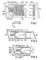
- FIG. 1 there is shown schematically in plan view a surface acoustic wave filter consisting of a substrate SU, preferably lithium niobate, able to propagate surface acoustic waves at a surface thereof and two transducers Tl, T2 formed on the surface, one transducer to launch and one transducer to receive surface acoustic waves at the surface along a propagation path P through the transducers T1, T2.
- the ends of the substrate SU are covered with surface acoustic wave absorbant material AB and are angled to deflect any residual reflected surface acoustic waves away from the propagation path P.
- Each transducer T1, T2 includes an interdigital array of two overlapping sets of electrodes, each set being connected to one of two opposite bus bars.
- two overlapping sets of electrodes Ell, E12 are respectively connected to bus bars Bll, B12
- two overlapping sets of electrodes E21, E22 are respectively connected to bus bars B21, B22.
- Extensions of the bus bars B11, B12 lead respectively to terminal pads TP1, TP2 for the transducer T1.
- the length normal to the propagation path P of the electrode overlap envelope varies along the path P and the limits of the overlap envelope normal to the path P define the acoustic aperture A of the transducer Tl.
- This overlap envelope consists of a central mejor lobe Ll, minor lobes L?, L3 etc on one side of the major lobe along the path P and minor lobes L4, L5 etc on the other side of the major lobe Ll along the path P.
- bus bars Bll, B12 each extend within the acoustic aperture A.
- bus bar parts BPI, BP2 which are within the acoustic aperture A, which are inclined at an acute angle to the propagation path P and which closely follow the major lobe Ll.
- bus bar parts BP3, BP4 which are within the acoustic aperture A, which are not inclined to the propagation path F and which closely follow some of the minor lobes L2, L3, L4, L5 etc.
- the components of the surface acoustic waves reflected from the two edges of each inclined bus bar part BP1 and BP2 along the propagation path P that is to say the component reflected waves SW1 reflected from the edge closest to the overlap envelope and the component reflected waves SW2 reflected from the edge which forms part of one end of the transducer, are in antiphase at that maximum response frequency and so spurious signals due to the component reflected waves SM1 and SW2 at that frequency are substantially suppressed.
- Reliable fabrication of the transducer Tl is enhanced if the inclined bus bar parts BP1 and BP2 have a minimum width W determined by the odd integer n being not less than three.
- FIG. 2 the references shown have the significance of the same references shown in Figure 1.
- FIG. 1 There is shown schematically in plan view the filter of Figure 1 modified in that the transducer electrodes are not shown, an earth strip ES between the transducers is shown, and in that the outline shapes of the substrate, transducers and earth strip are approximately those suitable for a television receiver intermediate frequency filter.
- a substrate suitable for use with the in-line arrangement of the two transducers without a multistrip coupler is, for example, ⁇ ° rotated Y-cut X-propagating lithium niobate with 9 in the range 123 to 125°.
- Bus bar parts BP1 and BP2 are provided which are within the acoustic aperture A, which are inclined at an acute angle to the propagation path P, which closely follow the major lobe L1 and which have a width W according to the above-mentioned definition.
- Bus bar parts BP31, BP32, BP41 and BP42 are provided which are within the acoustic aperture A, which are not inclined to the propagation path P and which closely follow some of the minor lobes of the transducer Tl.
- Bus bar parts BP5, BP6, BP7 and BP8 are provided which are within the acoustic aperture A, which are inclined at right angles to the propagation path P and which have a width W according to the above-mentioned definition.
- the inclusion of the bus bar parts BP5, BP6 which closely follow the major lobe Ll and the bus bar parts BP7, BP8 which closely follow a minor lobe enables the extensions of the bus bars Bll and B12 within the acoustic aperture A to more closely follow the electrode overlap envelope than is the case with the bus bar configuration of Figure 2.
- the terminal pads TP1, TP2 are shown to have a parallelogram shape such that where they extend within the acoustic aperture A they also have a width W according to the above-mentioned definition for surface acoustic wave reflection suppression.
Landscapes
- Physics & Mathematics (AREA)
- Acoustics & Sound (AREA)
- Surface Acoustic Wave Elements And Circuit Networks Thereof (AREA)
Applications Claiming Priority (2)
| Application Number | Priority Date | Filing Date | Title |
|---|---|---|---|
| GB8040796A GB2090093A (en) | 1980-12-19 | 1980-12-19 | Acoustic wave devices |
| GB8040796 | 1980-12-19 |
Publications (2)
| Publication Number | Publication Date |
|---|---|
| EP0054988A1 true EP0054988A1 (de) | 1982-06-30 |
| EP0054988B1 EP0054988B1 (de) | 1984-10-03 |
Family
ID=10518114
Family Applications (1)
| Application Number | Title | Priority Date | Filing Date |
|---|---|---|---|
| EP81201296A Expired EP0054988B1 (de) | 1980-12-19 | 1981-11-23 | Einrichtung für akustische Oberflächenwellen |
Country Status (6)
| Country | Link |
|---|---|
| US (1) | US4420728A (de) |
| EP (1) | EP0054988B1 (de) |
| JP (1) | JPS57124917A (de) |
| CA (1) | CA1176720A (de) |
| DE (1) | DE3166518D1 (de) |
| GB (1) | GB2090093A (de) |
Cited By (2)
| Publication number | Priority date | Publication date | Assignee | Title |
|---|---|---|---|---|
| AU575440B2 (en) * | 1984-10-26 | 1988-07-28 | Siemens Aktiengesellschaft | An electric filter operating with acoustic waves |
| NL9220007A (nl) * | 1991-10-17 | 1993-10-01 | Rif O Z Mikroelektroniki | Met akoestische oppervlaktegolven werkend banddoorlaatfilter |
Families Citing this family (9)
| Publication number | Priority date | Publication date | Assignee | Title |
|---|---|---|---|---|
| GB2120890B (en) * | 1982-04-19 | 1985-11-27 | Philips Electronic Associated | Acoustic surface wave device |
| US4604595A (en) * | 1982-06-16 | 1986-08-05 | Murata Manufacturing Co., Ltd. | Surface acoustic wave device having interdigitated comb electrodes weighted for odd/even response |
| GB2132844A (en) * | 1982-12-22 | 1984-07-11 | Philips Electronic Associated | Surface acoustic wave device |
| CA1254994A (en) * | 1985-03-29 | 1989-05-30 | Mark S. Suthers | Saw devices with reflection-suppressing fingers |
| US4870312A (en) * | 1987-02-19 | 1989-09-26 | Hazeltine Corporation | Surface wave device having anti-reflective shield |
| JPH0159323U (de) * | 1987-10-09 | 1989-04-13 | ||
| RU2121213C1 (ru) * | 1991-10-17 | 1998-10-27 | Акционерное общество открытого типа "РИФ" | Полосовой фильтр на поверхностных акустических волнах (пав) |
| JPH07212177A (ja) * | 1994-01-14 | 1995-08-11 | Murata Mfg Co Ltd | 表面波フィルタ |
| US6516665B1 (en) * | 1999-06-17 | 2003-02-11 | The Penn State Research Foundation | Micro-electro-mechanical gyroscope |
Citations (5)
| Publication number | Priority date | Publication date | Assignee | Title |
|---|---|---|---|---|
| US3955159A (en) * | 1973-09-17 | 1976-05-04 | U.S. Philips Corporation | Acoustic surface wave devices |
| FR2390830A1 (fr) * | 1977-05-09 | 1978-12-08 | Murata Manufacturing Co | Composant acoustique a onde de surface |
| GB2000932A (en) * | 1977-06-20 | 1979-01-17 | Hitachi Ltd | Elastic surface wave device |
| FR2412984A1 (fr) * | 1977-12-21 | 1979-07-20 | Tektronix Inc | Transducteur a ondes acoustiques de surface ameliore |
| DE2839851B1 (de) * | 1978-09-13 | 1979-12-06 | Siemens Ag | Oberflaechenwellenanordnung mit verbesserter Stoersignalunterdrueckung |
Family Cites Families (3)
| Publication number | Priority date | Publication date | Assignee | Title |
|---|---|---|---|---|
| GB1585087A (en) * | 1976-07-29 | 1981-02-25 | Plessey Co Ltd | Surface acoustic wave filters |
| JPS5333557A (en) * | 1976-08-24 | 1978-03-29 | Toshiba Corp | Elastic surface wave element |
| US4205285A (en) * | 1978-11-03 | 1980-05-27 | Gte Laboratories Incorporated | Acoustic surface wave device |
-
1980
- 1980-12-19 GB GB8040796A patent/GB2090093A/en not_active Withdrawn
-
1981
- 1981-11-23 DE DE8181201296T patent/DE3166518D1/de not_active Expired
- 1981-11-23 EP EP81201296A patent/EP0054988B1/de not_active Expired
- 1981-12-03 US US06/327,142 patent/US4420728A/en not_active Expired - Fee Related
- 1981-12-16 JP JP56201751A patent/JPS57124917A/ja active Pending
- 1981-12-17 CA CA000392595A patent/CA1176720A/en not_active Expired
Patent Citations (5)
| Publication number | Priority date | Publication date | Assignee | Title |
|---|---|---|---|---|
| US3955159A (en) * | 1973-09-17 | 1976-05-04 | U.S. Philips Corporation | Acoustic surface wave devices |
| FR2390830A1 (fr) * | 1977-05-09 | 1978-12-08 | Murata Manufacturing Co | Composant acoustique a onde de surface |
| GB2000932A (en) * | 1977-06-20 | 1979-01-17 | Hitachi Ltd | Elastic surface wave device |
| FR2412984A1 (fr) * | 1977-12-21 | 1979-07-20 | Tektronix Inc | Transducteur a ondes acoustiques de surface ameliore |
| DE2839851B1 (de) * | 1978-09-13 | 1979-12-06 | Siemens Ag | Oberflaechenwellenanordnung mit verbesserter Stoersignalunterdrueckung |
Cited By (2)
| Publication number | Priority date | Publication date | Assignee | Title |
|---|---|---|---|---|
| AU575440B2 (en) * | 1984-10-26 | 1988-07-28 | Siemens Aktiengesellschaft | An electric filter operating with acoustic waves |
| NL9220007A (nl) * | 1991-10-17 | 1993-10-01 | Rif O Z Mikroelektroniki | Met akoestische oppervlaktegolven werkend banddoorlaatfilter |
Also Published As
| Publication number | Publication date |
|---|---|
| JPS57124917A (en) | 1982-08-04 |
| CA1176720A (en) | 1984-10-23 |
| EP0054988B1 (de) | 1984-10-03 |
| DE3166518D1 (en) | 1984-11-08 |
| GB2090093A (en) | 1982-06-30 |
| US4420728A (en) | 1983-12-13 |
Similar Documents
| Publication | Publication Date | Title |
|---|---|---|
| US4353046A (en) | Surface acoustic wave device with reflectors | |
| US6346864B1 (en) | Saw resonator filter and duplexer utilizing SH waves, substrate edge reflection, and sub-interdigital transducer portions | |
| US7023300B2 (en) | Surface wave devices with low passband ripple | |
| US4420728A (en) | Acoustic wave devices | |
| EP0024927A2 (de) | Resonatorvorrichtung mit akustischen Oberflächenwellen | |
| US4866325A (en) | Surface acoustic wave transducer | |
| EP0026114B1 (de) | Vorrichtung mit akustischen Oberflächenwellen | |
| US6346761B1 (en) | Surface acoustic wave device capable of suppressing spurious response due to non-harmonic higher-order modes | |
| GB2123638A (en) | Surface acoustic wave device | |
| US4350963A (en) | Surface acoustic wave device | |
| EP0562876B1 (de) | Akustische Oberflächenwellenfilteranordnung | |
| JPH0353802B2 (de) | ||
| US4370633A (en) | Acoustic wave bandpass electrical filters | |
| US5714830A (en) | Free edge reflective-type surface acoustic wave device | |
| US4346322A (en) | Elastic surface wave device | |
| JP3137064B2 (ja) | 弾性表面波フィルタ | |
| JPS6231860B2 (de) | ||
| US4427956A (en) | Acoustic wave bandpass electrical filters | |
| US5471179A (en) | Surface acoustic wave bandpass filter including unique V-shaped electrode and phase compensator | |
| US5548256A (en) | Saw filter having electrodes for relaxation of electric field concentration | |
| US3873946A (en) | Acoustic surface wave tapped delay line | |
| US4375624A (en) | Surface wave acoustic device with compensation for spurious frequency response modes | |
| US4330767A (en) | Surface acoustic wave device | |
| US4258342A (en) | Elastic surface wave device | |
| US4205280A (en) | Surface wave device with suppressed boundary-reflected waves |
Legal Events
| Date | Code | Title | Description |
|---|---|---|---|
| PUAI | Public reference made under article 153(3) epc to a published international application that has entered the european phase |
Free format text: ORIGINAL CODE: 0009012 |
|
| AK | Designated contracting states |
Designated state(s): DE FR GB |
|
| RAP1 | Party data changed (applicant data changed or rights of an application transferred) |
Owner name: N.V. PHILIPS' GLOEILAMPENFABRIEKEN Owner name: PHILIPS ELECTRONIC AND ASSOCIATED INDUSTRIES LIMIT |
|
| 17P | Request for examination filed |
Effective date: 19821101 |
|
| GRAA | (expected) grant |
Free format text: ORIGINAL CODE: 0009210 |
|
| AK | Designated contracting states |
Designated state(s): DE FR GB |
|
| REF | Corresponds to: |
Ref document number: 3166518 Country of ref document: DE Date of ref document: 19841108 |
|
| PGFP | Annual fee paid to national office [announced via postgrant information from national office to epo] |
Ref country code: FR Payment date: 19841129 Year of fee payment: 4 |
|
| ET | Fr: translation filed | ||
| PGFP | Annual fee paid to national office [announced via postgrant information from national office to epo] |
Ref country code: DE Payment date: 19850125 Year of fee payment: 4 |
|
| PLBE | No opposition filed within time limit |
Free format text: ORIGINAL CODE: 0009261 |
|
| STAA | Information on the status of an ep patent application or granted ep patent |
Free format text: STATUS: NO OPPOSITION FILED WITHIN TIME LIMIT |
|
| 26N | No opposition filed | ||
| PG25 | Lapsed in a contracting state [announced via postgrant information from national office to epo] |
Ref country code: GB Effective date: 19881123 |
|
| GBPC | Gb: european patent ceased through non-payment of renewal fee | ||
| PG25 | Lapsed in a contracting state [announced via postgrant information from national office to epo] |
Ref country code: DE Effective date: 19890801 |
|
| PG25 | Lapsed in a contracting state [announced via postgrant information from national office to epo] |
Ref country code: FR Effective date: 19900731 |
|
| REG | Reference to a national code |
Ref country code: FR Ref legal event code: ST |