EP0055116A2 - Pompe d'injection de combustible - Google Patents
Pompe d'injection de combustible Download PDFInfo
- Publication number
- EP0055116A2 EP0055116A2 EP81306000A EP81306000A EP0055116A2 EP 0055116 A2 EP0055116 A2 EP 0055116A2 EP 81306000 A EP81306000 A EP 81306000A EP 81306000 A EP81306000 A EP 81306000A EP 0055116 A2 EP0055116 A2 EP 0055116A2
- Authority
- EP
- European Patent Office
- Prior art keywords
- plunger
- fuel
- fuel injection
- injection pump
- housing
- Prior art date
- Legal status (The legal status is an assumption and is not a legal conclusion. Google has not performed a legal analysis and makes no representation as to the accuracy of the status listed.)
- Granted
Links
- 239000000446 fuel Substances 0.000 title claims abstract description 80
- 238000002347 injection Methods 0.000 title claims abstract description 35
- 239000007924 injection Substances 0.000 title claims abstract description 35
- 230000004044 response Effects 0.000 claims description 4
- 238000012937 correction Methods 0.000 abstract description 2
- 238000005086 pumping Methods 0.000 description 3
- 230000008859 change Effects 0.000 description 2
- 230000006835 compression Effects 0.000 description 2
- 238000007906 compression Methods 0.000 description 2
- 238000010276 construction Methods 0.000 description 2
- 239000002826 coolant Substances 0.000 description 2
- 238000013461 design Methods 0.000 description 2
- 238000010586 diagram Methods 0.000 description 2
- 230000006870 function Effects 0.000 description 2
- 230000007246 mechanism Effects 0.000 description 2
- 230000009471 action Effects 0.000 description 1
- 230000007812 deficiency Effects 0.000 description 1
- 230000010354 integration Effects 0.000 description 1
- 238000005259 measurement Methods 0.000 description 1
- 230000004048 modification Effects 0.000 description 1
- 238000012986 modification Methods 0.000 description 1
- 238000012545 processing Methods 0.000 description 1
Images

Classifications
-
- F—MECHANICAL ENGINEERING; LIGHTING; HEATING; WEAPONS; BLASTING
- F02—COMBUSTION ENGINES; HOT-GAS OR COMBUSTION-PRODUCT ENGINE PLANTS
- F02M—SUPPLYING COMBUSTION ENGINES IN GENERAL WITH COMBUSTIBLE MIXTURES OR CONSTITUENTS THEREOF
- F02M51/00—Fuel-injection apparatus characterised by being operated electrically
- F02M51/04—Pumps peculiar thereto
-
- F—MECHANICAL ENGINEERING; LIGHTING; HEATING; WEAPONS; BLASTING
- F02—COMBUSTION ENGINES; HOT-GAS OR COMBUSTION-PRODUCT ENGINE PLANTS
- F02D—CONTROLLING COMBUSTION ENGINES
- F02D41/00—Electrical control of supply of combustible mixture or its constituents
- F02D41/30—Controlling fuel injection
- F02D41/38—Controlling fuel injection of the high pressure type
- F02D41/40—Controlling fuel injection of the high pressure type with means for controlling injection timing or duration
-
- F—MECHANICAL ENGINEERING; LIGHTING; HEATING; WEAPONS; BLASTING
- F02—COMBUSTION ENGINES; HOT-GAS OR COMBUSTION-PRODUCT ENGINE PLANTS
- F02M—SUPPLYING COMBUSTION ENGINES IN GENERAL WITH COMBUSTIBLE MIXTURES OR CONSTITUENTS THEREOF
- F02M57/00—Fuel-injectors combined or associated with other devices
- F02M57/02—Injectors structurally combined with fuel-injection pumps
- F02M57/022—Injectors structurally combined with fuel-injection pumps characterised by the pump drive
- F02M57/027—Injectors structurally combined with fuel-injection pumps characterised by the pump drive electric
-
- F—MECHANICAL ENGINEERING; LIGHTING; HEATING; WEAPONS; BLASTING
- F02—COMBUSTION ENGINES; HOT-GAS OR COMBUSTION-PRODUCT ENGINE PLANTS
- F02M—SUPPLYING COMBUSTION ENGINES IN GENERAL WITH COMBUSTIBLE MIXTURES OR CONSTITUENTS THEREOF
- F02M2200/00—Details of fuel-injection apparatus, not otherwise provided for
- F02M2200/24—Fuel-injection apparatus with sensors
-
- Y—GENERAL TAGGING OF NEW TECHNOLOGICAL DEVELOPMENTS; GENERAL TAGGING OF CROSS-SECTIONAL TECHNOLOGIES SPANNING OVER SEVERAL SECTIONS OF THE IPC; TECHNICAL SUBJECTS COVERED BY FORMER USPC CROSS-REFERENCE ART COLLECTIONS [XRACs] AND DIGESTS
- Y02—TECHNOLOGIES OR APPLICATIONS FOR MITIGATION OR ADAPTATION AGAINST CLIMATE CHANGE
- Y02T—CLIMATE CHANGE MITIGATION TECHNOLOGIES RELATED TO TRANSPORTATION
- Y02T10/00—Road transport of goods or passengers
- Y02T10/10—Internal combustion engine [ICE] based vehicles
- Y02T10/40—Engine management systems
Definitions
- This invention relates to fuel injection pumps.
- Fuel injection pumps are well known in the prior art.
- U.S. 3,990,413 shows a plunger type fuel injection pump with a delivery valve and a control means for varying the stroke of the plunger; however, these elements are not integrated into a single unit, there is no electromagnetic means for actuating the plunger, nor is the duration and magnitude of the fuel injector controlled electrically.
- US. 3,623,192 shows a fuel injection system in which fuel is pressurised behind a metering plunger to determine the length of time the plunger remains open. No electrical control is provided.
- U. S. 3,837,324. shows an integrated fuel injection assembly having a pump and nozzle assembly integrated, and solenoid means for controlling a fuel valve. However, two solenoids and associated control mechanisms are required.
- U.S. 4,044,745 shows an oscillating pump and an electromagnet, with stroke control means, but the actuating mechanism is not constructed in a compact manner, and the stroke control is not varied by controlling the pulses to an electromagnet.
- a fuel injection pump comprising a housing having a fuel inlet and a fuel outlet, a plunger reciprocable within the housing for pressurising fuel received from the inlet for discharge out of the outlet, a solenoid for reciprocating the plunger in the housing in response to electrical impulses supplied thereto, and sensor means for generating an electrical feedback signal representing the lergth of the stroke of the plunger during its reciprocation; and electrical control means for supplying electrical impulses to the solenoid, the duration of which vary in response to changes in the feedback signal to control the amount of fuel discharged from the outlet in accordance with a predetermined schedule.
- FIG. 1 shows a fuel injection pump 10.
- the pump 10 ia formed by a three-piece housing.
- the first portion , ' )f the housing comprises a conventional longitudinally extending fuel injector nozzle 12 having an outlet at its lower end which contains a fuel pressure actuated valve 14 that opens outwardly when the fuel pressure at the outlet reaches a sufficient level.
- the details of construction of this particular injector nozzle are not given since they are known and believed to be unnecessary for an understanding of the invention. Suffice it to say that it could be constructed as fully shown and described in U .S. 3,542,293 with a tension spring unit for maintaining the valve closed below a predetermined fuel pressure.
- the fuel injector nozzle 12 at its upper end contain a fuel inlet 16 that is connected to a suitable low pressure fuel supply line, not shown.
- a check valve and a pressure regulator are included in the line to permit entry of fuel into inlet 16 at a maintained pressure level, and to ensure closure of the inlet after actuation of the fuel injection pump to prevent leakage of fuel out of the supply line.
- the second portion of the housing of fuel injector pump 10, which is mounted at one end of the nozzle 12 forms a stationary core 18 of a solenoid 20. It includes a coil 22 surrounding a reciprocable armature 24 that is secured to the upper end of a plunger 26 to constitute a fuel pumping unit.
- the plunger 26 is coaxial with the nozzle 12 and has a projection 27 adapted to engage an adjustable stop 28 that is threaded coaxially with the plunger 26 through a cover 30 for coil 22.
- the cover 30 forms the third portion of the housing of the fuel injection pump 10, and is mounted on the opposite end of the core 18 from the nozzle 12.
- the stop 28 is hollow and contains a proximity sensor 32 connected by wiring 34 to an electrical control unit, not shown.
- the pumping action in this case is caused and controlled by the magnetic force generated in the solenoid coil 22.
- the quantity of fuel displaced by plunger 26 is determined by the magnitude and duration of the current pulse in the coil 22, while the timing of injection is defined by the timing of the pulse.
- the fuel injection pump 10 is intended to be controlled by a data processing and computing device, such as a microprocessor, which would continuously monitor the main operating conditions of the engine, such as airflow, EGR flow, RPM, coolant and fuel temperatures, for example, compute the required fuel delivery and injection timing, and generate and send out to all the fuel injection pumps 10 current pulses of such magnitude and duration, and with such timing as needed to produce the required stroke of the plunger 26 at the required instant.
- the microprocessor would also monitor the actual stroke of the fuel pumping plunger serving the individual engine cylinders.
- the correction device/portion of the microprocessor would modify the current pulse sent to the corresponding solenoid 20 until the required plunger stroke was achieved. Independent control of the fuel quantities injected into individual cylinders would assure the ability to maintain the required pattern of uniform cylinder-to-cylinder fuel distribution.
- the stroke of plunger 26 is determined by both the magnitude of the magnetic force impulse and its duration, the same plunger stroke can be achieved with a variety of impulses with different combinations of' force and its duration, as long as the total energy of the impulses is the same.
- a substantial degree of freedom exists to vary the rate of fuel injection. For every engine speed and load combination, therefore, the microprocessor could select an impulse with offered the best compromise between the most desirable rate of injection in terms of fuel flow per millisecond and the desirable duration of injection expressed in crankshaft degrees.
- fuel enters the fuel inlet 16 through a suitable check valve, and,when coil 22 is not energised, fuel pressure keeps the plunger 26 in its uppermost position pressed against the adjustable stop 28, Adjusting the stop will calibrate the air gap in the solenoid.
- Energising the coil 22 drives the plunger downward, thus pressurising the fuel trapped in the body of nozzle 12 until the opening pressure of the valve is reached, and the valve 14 opens to allow fuel to be injected into the cylinder.
- fuel pressure stops the downward movement of plunger 26 and the injection is terminated. Since the mass of plunger 26 is small in comparison with the magnitude of the pressure force, the deceleration of the plunger is very fast and results in a sharp cut-off of injection.
- a plunger return spring may be incorporated in the design. Expansion of the compressed fuel (and return spring, if any) moves the plunger up until the pressure drops below the supply pressure and the inlet check valve opens, letting in the supply fuel. The cycle ends with the nozzle 12 refilled with fuel and the plunger up against the adjustable stop 28, ready for the next injection stroke.
- the interior of the coil 22 is vented through an opening (not shown) into an intake air duct leading to the engine air intake throttle. Therefore, any fuel leaking past the plunger 26 evaporates, and mixed with the intake air, will find its way into the cylinders. As a result, the fuel delivery into the cylinder is essentially independent of the leakage and equals the displaced volume less the compression volume.
- the signals from the proximity sensor 32 are fed into the microprocessor, not shown, and permit the latter to evaluate the actual plunger stroke, compare it with the required one, and modify, if necessary, the current impulse sent to coil 22, until the actual stroke matches the required one.
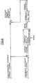
- Figure 2 shows the logic diagram for the closed loop plunger stroke control system.
- the feedforward signal is generated by the microprocessor on the basis of information it receives from various engine sensors and is computed as a function of inter alia, the airflow, engine speed and coolant temperature according to a predetermined schedule, stored in the microprocessor memory.
- This basic signal which defines a certain pulse duration and is the same for all unit injectors in the engine, represents a demand for a specific plunger stroke.
- the feedback signal which is supplied by the position sensor 32, represents the actual plunger stroke during the last engine cycle. If the actual stroke equals the required one, the two signals are equal, and the error signal is zero. Whenever the plunger stroke differs from the required value, an error signal appears in the system, and the microprocessor begins to correct the stroke by incrementing the pulse duration so as to bring the error signal close to zero.
- the mte at which the pulse duration signal is incremented is a function of both the magnitude of the error signal and engine speed.
- FIG 3 illustrates a further embodiment of the invention.
- the injector nozzle 12' is not integrated with the housing in an end-to-end relationship, as shown in Figure 1, but is remotely located and connected to the outlet 40 of the housing by tubing 42.
- the fuel injection pump, indicated generally at 44 is, however, constructed generally in a manner similar to that shown in Figure 1. It contains a solenoid 46 that includes a coil 48 surrounding a stationary core element 50. The latter is adjustably fixed to a lower housing portion 52 by screws 54. The lower housing portion 52 defines the fuel outlet 40.
- a plunger 56 is fixed to the movable armature 58 of the solenoid 46.
- the solenoid 46 is enclosed by an upper housing portion 60 and a cover 62. The latter has a raised boss 64.
- a proximity sensor 66 projects through cover 62 adjacent the armature and is mounted coaxially with the plunger 56.
- a vent line 68 is provided to collect fuel leakage past the armature 58.
Landscapes
- Engineering & Computer Science (AREA)
- Chemical & Material Sciences (AREA)
- Combustion & Propulsion (AREA)
- Mechanical Engineering (AREA)
- General Engineering & Computer Science (AREA)
- Fuel-Injection Apparatus (AREA)
- Electrical Control Of Air Or Fuel Supplied To Internal-Combustion Engine (AREA)
- High-Pressure Fuel Injection Pump Control (AREA)
Applications Claiming Priority (2)
| Application Number | Priority Date | Filing Date | Title |
|---|---|---|---|
| US06/219,107 US4327695A (en) | 1980-12-22 | 1980-12-22 | Unit fuel injector assembly with feedback control |
| US219107 | 1980-12-22 |
Publications (3)
| Publication Number | Publication Date |
|---|---|
| EP0055116A2 true EP0055116A2 (fr) | 1982-06-30 |
| EP0055116A3 EP0055116A3 (en) | 1983-09-21 |
| EP0055116B1 EP0055116B1 (fr) | 1987-03-04 |
Family
ID=22817912
Family Applications (1)
| Application Number | Title | Priority Date | Filing Date |
|---|---|---|---|
| EP81306000A Expired EP0055116B1 (fr) | 1980-12-22 | 1981-12-21 | Pompe d'injection de combustible |
Country Status (5)
| Country | Link |
|---|---|
| US (1) | US4327695A (fr) |
| EP (1) | EP0055116B1 (fr) |
| JP (1) | JPS57110727A (fr) |
| CA (1) | CA1175290A (fr) |
| DE (1) | DE3175952D1 (fr) |
Cited By (4)
| Publication number | Priority date | Publication date | Assignee | Title |
|---|---|---|---|---|
| GB2161959A (en) * | 1984-07-20 | 1986-01-22 | Bosch Gmbh Robert | Fuel injection quantity regulating means |
| EP0316164A1 (fr) * | 1987-11-10 | 1989-05-17 | Her Majesty The Queen In Right Of New Zealand | Pompe à débit variable pour fluide |
| EP0391573A3 (fr) * | 1989-04-03 | 1991-01-30 | General Motors Corporation | Méthode et dispositif de commande de carburant en boucle fermée |
| EP2495430A1 (fr) * | 2011-03-04 | 2012-09-05 | Continental Automotive GmbH | Système de fourniture de carburant permettant de fournir du carburant dans un injecteur à carburant |
Families Citing this family (29)
| Publication number | Priority date | Publication date | Assignee | Title |
|---|---|---|---|---|
| DE3302293A1 (de) * | 1983-01-25 | 1984-07-26 | Klöckner-Humboldt-Deutz AG, 5000 Köln | Kraftstoffeinspritzvorrichtung fuer brennkraftmaschinen |
| JPS60147551A (ja) * | 1984-01-13 | 1985-08-03 | Nippon Soken Inc | デイ−ゼル機関の吸気絞り制御装置 |
| NL8501647A (nl) * | 1985-06-06 | 1987-01-02 | Volvo Car Bv | Brandstofinjector. |
| BR9007384A (pt) * | 1989-05-19 | 1992-04-21 | Orbital Eng Pty | Metodo e aparelho para controlar a operacao de um solenoide |
| US5267545A (en) * | 1989-05-19 | 1993-12-07 | Orbital Engine Company (Australia) Pty. Limited | Method and apparatus for controlling the operation of a solenoid |
| JPH07504475A (ja) * | 1992-03-04 | 1995-05-18 | フィヒト ゲゼルシャフト ミット ベシュレンクテル ハフツング | 電磁駆動往復ポンプの励起コイルの駆動用回路 |
| JPH0893601A (ja) * | 1994-09-22 | 1996-04-09 | Zexel Corp | 燃料噴射ノズル |
| JPH08210168A (ja) * | 1995-02-02 | 1996-08-20 | Sanshin Ind Co Ltd | エンジンの運転制御装置 |
| US5687050A (en) * | 1995-07-25 | 1997-11-11 | Ficht Gmbh | Electronic control circuit for an internal combustion engine |
| DE19527629A1 (de) * | 1995-07-28 | 1997-01-30 | Bosch Gmbh Robert | Kraftstoffpumpe |
| DE19642653C5 (de) * | 1996-10-16 | 2008-02-21 | Daimler Ag | Verfahren zur Bildung eines zündfähigen Kraftstoff/Luft-Gemisches |
| US5895844A (en) * | 1997-05-29 | 1999-04-20 | Outboard Marine Corporation | Precise fuel flow measurement with modified fluid control valve |
| US6942469B2 (en) * | 1997-06-26 | 2005-09-13 | Crystal Investments, Inc. | Solenoid cassette pump with servo controlled volume detection |
| US6135357A (en) * | 1998-11-23 | 2000-10-24 | General Electric Company | Apparatus for atomizing high-viscosity fluids |
| US6264432B1 (en) * | 1999-09-01 | 2001-07-24 | Liquid Metronics Incorporated | Method and apparatus for controlling a pump |
| US6283095B1 (en) * | 1999-12-16 | 2001-09-04 | Bombardier Motor Corporation Of America | Quick start fuel injection apparatus and method |
| AU2001231984A1 (en) * | 2000-01-27 | 2001-08-07 | Keith Trevor Lawes | Fuel injector |
| JP3075074U (ja) | 2000-07-24 | 2001-02-09 | 船井電機株式会社 | オーディオ用ヘッド |
| WO2002012708A1 (fr) * | 2000-08-02 | 2002-02-14 | Mikuni Corporation | Injecteur de carburant a commande electronique |
| CN1308589C (zh) * | 2001-11-29 | 2007-04-04 | 三国股份有限公司 | 燃料喷射泵的驱动方法 |
| US20050175481A1 (en) * | 2002-09-23 | 2005-08-11 | Harbuck E. S. | Low cost fuel pump and filter assembly |
| US7216630B2 (en) * | 2004-10-21 | 2007-05-15 | Siemens Diesel Systems Technology | System and method to control spool stroke motion |
| WO2014066696A1 (fr) | 2012-10-25 | 2014-05-01 | Picospray, Llc | Système d'injection de carburant |
| USD763413S1 (en) * | 2013-02-14 | 2016-08-09 | Yanmar Co., Ltd. | Fuel injection pipe |
| USD762823S1 (en) * | 2013-02-14 | 2016-08-02 | Yanmar Co., Ltd. | Fuel injection pipe |
| EP3455498B1 (fr) | 2016-05-12 | 2024-07-03 | Briggs & Stratton, LLC | Injecteur de distribution de carburant |
| WO2018022754A1 (fr) | 2016-07-27 | 2018-02-01 | Picospray, Llc | Injecteur à pompe à mouvement alternatif |
| US10947940B2 (en) | 2017-03-28 | 2021-03-16 | Briggs & Stratton, Llc | Fuel delivery system |
| US11668270B2 (en) | 2018-10-12 | 2023-06-06 | Briggs & Stratton, Llc | Electronic fuel injection module |
Family Cites Families (17)
| Publication number | Priority date | Publication date | Assignee | Title |
|---|---|---|---|---|
| US1534829A (en) * | 1919-04-09 | 1925-04-21 | Albert R Behnke | Electrically-operated fuel injector |
| US3625192A (en) * | 1969-12-12 | 1971-12-07 | Allis Chalmers Mfg Co | Fuel injection nozzle with hydraulic valve-closing means |
| US3724436A (en) * | 1970-04-02 | 1973-04-03 | Nippon Denso Co | Fuel feed control device for internal combustion engines |
| DE2126653A1 (de) * | 1971-05-28 | 1972-12-07 | Robert Bosch Gmbh, 7000 Stuttgart | Kraftstoffeinspritzeinrichtung für Brennkraftmaschinen |
| DE2126736A1 (de) * | 1971-05-28 | 1972-12-07 | Bosch Gmbh Robert | Kraftstoffeinspntzanlage fur Brenn kraftmaschinen |
| DE2126777A1 (de) * | 1971-05-28 | 1972-12-14 | Bosch Gmbh Robert | Pumpe Düse zur Kraftstoffeinspritzung fur Brennkraftmaschinen |
| DE2213776A1 (de) * | 1972-03-22 | 1973-09-27 | Bosch Gmbh Robert | Kraftstoffeinspritzanlage fuer brennkraftmaschinen |
| DE2309916C3 (de) * | 1973-02-28 | 1981-03-26 | Franz Prof. Dipl.-Ing. Dr.Techn. 5100 Aachen Pischinger | Kraftstoffeinspritzvorrichtung für Brennkraftmaschinen |
| US4044745A (en) * | 1973-03-14 | 1977-08-30 | Holec, N.V. | Injector pump |
| DE2356335A1 (de) * | 1973-11-10 | 1975-05-15 | Bach & Co | Einspritzpumpenelement mit elektromagnetischem antrieb |
| DE2854921A1 (de) * | 1977-12-21 | 1979-07-05 | William H Leckie | Brennstoff-einspritzvorrichtung |
| DE2809122A1 (de) * | 1978-03-03 | 1979-09-06 | Bosch Gmbh Robert | Einspritzvorrichtung fuer eine brennkraftmaschine |
| GB2017205B (en) * | 1978-03-22 | 1982-06-23 | Lucas Industries Ltd | Fuel pumping apparatus |
| GB1601006A (en) * | 1978-04-05 | 1981-10-21 | Lucas Industries Ltd | Fuel injection pumping apparatus |
| US4235374A (en) * | 1979-01-25 | 1980-11-25 | The Bendix Corporation | Electronically controlled diesel unit injector |
| US4295453A (en) * | 1979-02-09 | 1981-10-20 | Lucas Industries Limited | Fuel system for an internal combustion engine |
| US4247044A (en) * | 1979-12-26 | 1981-01-27 | General Motors Corporation | Compression operated injector |
-
1980
- 1980-12-22 US US06/219,107 patent/US4327695A/en not_active Expired - Fee Related
-
1981
- 1981-11-04 JP JP56177021A patent/JPS57110727A/ja active Pending
- 1981-12-18 CA CA000392727A patent/CA1175290A/fr not_active Expired
- 1981-12-21 EP EP81306000A patent/EP0055116B1/fr not_active Expired
- 1981-12-21 DE DE8181306000T patent/DE3175952D1/de not_active Expired
Cited By (5)
| Publication number | Priority date | Publication date | Assignee | Title |
|---|---|---|---|---|
| GB2161959A (en) * | 1984-07-20 | 1986-01-22 | Bosch Gmbh Robert | Fuel injection quantity regulating means |
| EP0316164A1 (fr) * | 1987-11-10 | 1989-05-17 | Her Majesty The Queen In Right Of New Zealand | Pompe à débit variable pour fluide |
| US4940035A (en) * | 1987-11-10 | 1990-07-10 | Her Majesty The Queen In Right Of New Zealand | Variable flow rate pump for fluid |
| EP0391573A3 (fr) * | 1989-04-03 | 1991-01-30 | General Motors Corporation | Méthode et dispositif de commande de carburant en boucle fermée |
| EP2495430A1 (fr) * | 2011-03-04 | 2012-09-05 | Continental Automotive GmbH | Système de fourniture de carburant permettant de fournir du carburant dans un injecteur à carburant |
Also Published As
| Publication number | Publication date |
|---|---|
| CA1175290A (fr) | 1984-10-02 |
| EP0055116A3 (en) | 1983-09-21 |
| DE3175952D1 (en) | 1987-04-09 |
| EP0055116B1 (fr) | 1987-03-04 |
| JPS57110727A (en) | 1982-07-09 |
| US4327695A (en) | 1982-05-04 |
Similar Documents
| Publication | Publication Date | Title |
|---|---|---|
| EP0055116A2 (fr) | Pompe d'injection de combustible | |
| US6188561B1 (en) | Circuit for driving the excitation coil of an electromagnetically driven reciprocating pump | |
| US4964571A (en) | Actuator for accumulator type fuel injection nozzle | |
| US4754735A (en) | Control of fuel injection apparatus for internal combustion engines | |
| US4300509A (en) | Fuel injection and control systems | |
| US6877679B2 (en) | Fuel injector | |
| US4295453A (en) | Fuel system for an internal combustion engine | |
| US4329951A (en) | Fuel injection system | |
| GB2034401A (en) | Regulating device for a fuel injection pump | |
| US3623460A (en) | Fuel injection valve for internal combustion engines | |
| US4355620A (en) | Fuel system for an internal combustion engine | |
| US4964389A (en) | Fuel injection device for internal combustion engines | |
| US5341785A (en) | Fuel delivery system for internal combustion engines | |
| US5104046A (en) | Fuel injection having a single solenoid | |
| US4022174A (en) | Electromagnetically actuated pumps | |
| JP2587047B2 (ja) | 内燃機関用の燃料噴射装置 | |
| GB2069718A (en) | Fuel injection system | |
| US4272027A (en) | Fuel injection pumping apparatus | |
| CA1100836A (fr) | Traduction non-disponible | |
| ATE82043T1 (de) | Brennstoffeinspritzvorrichtung. | |
| US1664607A (en) | Fuel-injection system | |
| EP0055117B1 (fr) | Pompe d'injection de combustible | |
| CN113123910B (zh) | 一种发动机电控燃油喷射系统 | |
| GB2185598A (en) | Fuel injection pump for an internal combustion engine | |
| US4060347A (en) | Liquid fuel pumping apparatus |
Legal Events
| Date | Code | Title | Description |
|---|---|---|---|
| PUAI | Public reference made under article 153(3) epc to a published international application that has entered the european phase |
Free format text: ORIGINAL CODE: 0009012 |
|
| AK | Designated contracting states |
Designated state(s): DE FR GB |
|
| PUAL | Search report despatched |
Free format text: ORIGINAL CODE: 0009013 |
|
| AK | Designated contracting states |
Designated state(s): DE FR GB |
|
| 17P | Request for examination filed |
Effective date: 19831202 |
|
| GRAA | (expected) grant |
Free format text: ORIGINAL CODE: 0009210 |
|
| AK | Designated contracting states |
Kind code of ref document: B1 Designated state(s): DE FR GB |
|
| PG25 | Lapsed in a contracting state [announced via postgrant information from national office to epo] |
Ref country code: FR Free format text: THE PATENT HAS BEEN ANNULLED BY A DECISION OF A NATIONAL AUTHORITY Effective date: 19870304 |
|
| REF | Corresponds to: |
Ref document number: 3175952 Country of ref document: DE Date of ref document: 19870409 |
|
| EN | Fr: translation not filed | ||
| REG | Reference to a national code |
Ref country code: GB Ref legal event code: 746 |
|
| PLBE | No opposition filed within time limit |
Free format text: ORIGINAL CODE: 0009261 |
|
| STAA | Information on the status of an ep patent application or granted ep patent |
Free format text: STATUS: NO OPPOSITION FILED WITHIN TIME LIMIT |
|
| 26N | No opposition filed | ||
| PGFP | Annual fee paid to national office [announced via postgrant information from national office to epo] |
Ref country code: GB Payment date: 19941122 Year of fee payment: 14 |
|
| PGFP | Annual fee paid to national office [announced via postgrant information from national office to epo] |
Ref country code: DE Payment date: 19941208 Year of fee payment: 14 |
|
| PG25 | Lapsed in a contracting state [announced via postgrant information from national office to epo] |
Ref country code: DE Effective date: 19951117 |
|
| PG25 | Lapsed in a contracting state [announced via postgrant information from national office to epo] |
Ref country code: GB Effective date: 19951221 |
|
| GBPC | Gb: european patent ceased through non-payment of renewal fee |
Effective date: 19951221 |