EP0055155A1 - Articulation, notamment pour panneau basculant - Google Patents
Articulation, notamment pour panneau basculant Download PDFInfo
- Publication number
- EP0055155A1 EP0055155A1 EP81401874A EP81401874A EP0055155A1 EP 0055155 A1 EP0055155 A1 EP 0055155A1 EP 81401874 A EP81401874 A EP 81401874A EP 81401874 A EP81401874 A EP 81401874A EP 0055155 A1 EP0055155 A1 EP 0055155A1
- Authority
- EP
- European Patent Office
- Prior art keywords
- axis
- washer
- lateral
- articulation
- head
- Prior art date
- Legal status (The legal status is an assumption and is not a legal conclusion. Google has not performed a legal analysis and makes no representation as to the accuracy of the status listed.)
- Granted
Links
- 230000000295 complement effect Effects 0.000 claims description 2
- 238000003754 machining Methods 0.000 description 1
- 238000000034 method Methods 0.000 description 1
- 238000003032 molecular docking Methods 0.000 description 1
- 238000000465 moulding Methods 0.000 description 1
- 230000002787 reinforcement Effects 0.000 description 1
- 230000003014 reinforcing effect Effects 0.000 description 1
Images
Classifications
-
- E—FIXED CONSTRUCTIONS
- E05—LOCKS; KEYS; WINDOW OR DOOR FITTINGS; SAFES
- E05D—HINGES OR SUSPENSION DEVICES FOR DOORS, WINDOWS OR WINGS
- E05D7/00—Hinges or pivots of special construction
- E05D7/10—Hinges or pivots of special construction to allow easy separation or connection of the parts at the hinge axis
- E05D7/1005—Hinges or pivots of special construction to allow easy separation or connection of the parts at the hinge axis by axially moving free pins, balls or sockets
-
- E—FIXED CONSTRUCTIONS
- E05—LOCKS; KEYS; WINDOW OR DOOR FITTINGS; SAFES
- E05D—HINGES OR SUSPENSION DEVICES FOR DOORS, WINDOWS OR WINGS
- E05D7/00—Hinges or pivots of special construction
- E05D7/10—Hinges or pivots of special construction to allow easy separation or connection of the parts at the hinge axis
- E05D7/1061—Hinges or pivots of special construction to allow easy separation or connection of the parts at the hinge axis in a radial direction
Definitions
- hinges of the usual type make it difficult, if not impossible, to use hinges of the usual type to ensure the mounting of a tilting panel, for example the lid of a motor vehicle luggage; this is particularly the case when the panel requires the presence of local reinforcements or stiffness ribs which prevent the machining of the bearings or the establishment of the tilting axis.
- French patent 562,418 describes a hinge comprising two elements connected to one another by an axis, one of these elements carrying a central stud mounted on said axis and disposed between two lateral studs integral with the other element and each provided with an end notch suitable for receiving the axis. But the axis can only be placed in the lateral tenons or separated from them in a particular position of the two elements of the articulation, which makes the assembly and disassembly of the articulation impractical.
- the present invention relates to a simple and compact articulation which can be used without difficulty for mounting a tilting panel and the mounting and dismounting of which are easy.
- each of the lateral tenons further comprises an external recess suitable for receiving a stop head arranged at one of the ends of the axis, for one of the lateral tenons, or a washer threaded on the other end of the axis, for the second lateral stud
- the axis is threaded into the central stud and this axis is engaged in the notches of the lateral studs, the central stud being received between these lateral studs.
- the axis is then moved in its longitudinal direction so that its head comes to lodge in the external recess of one of the lateral tenons. It only remains to thread the washer on the free end of the axle until it comes to lodge in the external recess of the other lateral tenon.
- the axis is then immobilized in the lateral tenons.
- an elastic pin can be provided, a branch of which is housed inside an orifice made at the end of the axis.
- the head of the axle and the washer can be cylindrical. But the shaft tube and possibly the washer can be shaped so that part of their periphery comes to bear substantially on the bottom of the corresponding recess, itself shaped in a complementary manner. The axis is thus immobilized further in rotation.
- the head of the axis, and the washer may, for example, have a flat, the bottom of the recesses of the lateral tenons being planar.
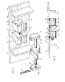
- the articulation comprises a stud 1 which is secured to an element 2 and is pivotally mounted about an axis 3 suitable for engaging inside two lateral studs 4 secured of a plate 5, the post 1 then being disposed between the posts 4.
- this pin 1 is only shown in Figure 1 in a position of axis 3 separate from the insert.
- Element 2 is, for example, a movable flap such as a trunk lid.
- the lateral pins 4 are separated from each other by a space 6 allowing the housing and the pivoting of the central pin 1.
- Each of these pins has, on the face opposite to the plate 5, an end notch 7 in which can accommodate the axis 3. It further comprises, on the side opposite to the space 6, a recess 8 which extends from the plate 4.
- the axis 3 carries at one of its ends a head 9 provided with a flat 9a and can receive, at its other end, a washer 10 of shape identical to that of the head 9 and provided like the latter with a flat 10a.
- a locking pin 11 which can be introduced into a hole 12 in the axis 3 is provided to prevent the washer 10 from coming out of the axis.
- the axis 3 is put in place in the post 1 and the assembly is presented so that this axis and this post engage respectively in the notches 7 of the posts 4 and in the space 6 separating these let's hold on.
- the head 9 of the axis 3 is oriented so that its flat 9a is oriented parallel to the bottom of the recess 8 of the adjacent stud 4, and this axis is made to undergo translation so that its head engages in the recess 8
- the flat 9a is determined so that it is then practically in contact with the bottom 8a of the recess, which is planar.
- the axis 3 is then immobilized both in rotation and in radial clearance. It only remains to thread the washer 10 on the end of the axis 3 by housing it in the recess 8 of the other tenon 4 and to introduce the pin 11 into the hole 12 to lock in position this washer .
- the articulation thus produced has a great compactness and ensures very good guidance thanks to the spreading of the surfaces in contact, both on the transverse plane at the level of the spans of the axis and on the plane of the central articulation flanks.
- the assembly and disassembly of the joint require very little lateral clearance and can be carried out quickly.
- the plate 5 can be fixed, the element 2 being movable. Conversely, this element can be fixed, the plate 5 being able to pivot relative to this element. If the two elements 2 and 5 are large and have significant overhangs, they can be connected to each other by several joints such as that which has just been described.
- the plate 5 with its tenons 4 and its webs 13 can constitute an assembly coming from molding and comprising a sole allowing its fixing on the element to be connected to the element 2.
- the present invention should not be considered as limited to the embodiment described and shown, but on the contrary covers all variants thereof.
- the head 9 and the washer 10 could be cylindrical, the recesses 8 being long enough to allow this head and this washer to be accommodated there respectively.
- the axis 3 would then still be immobilized radially but could pivot.
Landscapes
- Engineering & Computer Science (AREA)
- Mechanical Engineering (AREA)
- Pivots And Pivotal Connections (AREA)
- Joining Of Building Structures In Genera (AREA)
- Furniture Connections (AREA)
Abstract
Description
- Il se peut que des impératifs d'ordre fonctionnel ou dûs à la géométrie des structures rendent difficiles, voire impossible, l'utilisation de charnières de type usuel pour assurer le montage d'un panneau basculant, par exemple le couvercle d'un coffre à bagages de véhicule automobile; c'est le cas notamment lorsque le panneau nécessite la présence de renforts locaux ou de nervures de rigidité qui empêchent l'usinage des paliers ou la mise en place de l'axe de basculement.
- Le brevet français 562 418 décrit une articulation comprenant deux éléments reliés l'un à l'autre par un axe, l'un de ces éléments portant un tenon central monté sur ledit axe et disposé entre deux tenons latéraux solidaires de l'autre élément et munis chacun d'une encoche d'extrémité propre à recevoir l'axe. Mais l'axe ne peut être mis en place dans les tenons latéraux ou séparés de ceux-ci que dans ure position particulière des deux éléments de l'articulation, ce qui rend peu pratique le montage et le démontage de l'articulation.
- La présente invention a pour objet une articulation simple et compacte qui peut être utilisée sans difficultés pour le montage d'un panneau basculant et dont le montage et le démontage sont aisés.
- Cette articulation est caractérisée en ce que chacun des tenons latéraux comporte en outre un décrochement extérieur propre à recevoir une tête d'arrêt disposés à l'une des extrémités de l'axe, pour l'un des tenons latéraux, ou une rondelle enfilée sur l'autre extrémité de l'axe, pour le second tenon latéral.
- Pour monter l'articulation, on enfile l'axe dans le tenon central et on engage cet axe dans les encoches des tenons latéraux, le tenon central venant se loger entre ces tenons latéraux. On déplace ensuite l'axe dans sa direction longitudinale de façon que sa tête vienne se loger dans le décrochement extérieur de l'un des tenons latéraux. Il ne reste plus qu'à enfiler la rondelle sur l'extrémité libre de l'axe jusqu'à ce qu'elle vienne se loger dans le décrochement extérieur de l'autre tenon latéral. L'axe est alors immobilisé dans les tenons latéraux.
- Pour empêcher la rondelle de se dégager de l'axe, il peut être prévu une épingle élastique dont une branche vient se loger à l'intérieur d'un orifice pratiqué à l'extrémité de l'axe.
- La tête de l'axe et la rondelle peuvent être cylindriques. Mais le tube de l'axe et éventuellement la rondelle peuvent être conformés de façon qu'une partie de leur périphérie vienne sensiblement en appui sur le fond du décrochement correspondant, lui-même conformé de façon complémentaire. L'axe est ainsi immobilisé en outre en rotation. La tête de l'axe, et la rondelle peuvent, par exemple, comporter un méplat, le fond des décrochements des tenons latéraux étant plans.
- On a décrit ci-après, à titre d'exemple non limitatif, un mode de réalisation de l'articulation selon l'invention, avec référence au dessin annexé dans lequel :
- La Figure 1 est une vue en perspective de cette articulation, les deux éléments de celle-ci étant représentés séparés,
- La Figure 2 est une vue en plan de l'articulation montée.
- Telle qu'elle est représentée au dessin, l'articulation comprend un tenon 1 qui est solidaire d'un élément 2 et est monté pivotant autour d'un axe 3 propre à venir s'engager à l'intérieur de deux tenons latéraux 4 solidaires d'une plaquette 5, le tenon 1 étant alors disposé entre les tenons 4. Dans un but de clarté, ce tenon 1 n'est représenté à la Figure 1 que dans une position de l'axe 3 séparée de la plaquette. L'élément 2 est, par exemple, un volet mobile tel qu'un couvercle de malle arrière.
- Les tenons latéraux 4 sont séparés l'un de l'autre par un espace 6 permettant le logement et le pivotement du tenon central 1. Chacun de ces tenons comporte, sur la face opposés à la plaquette 5, une encoche d'extrémité 7 dans laquelle peut se loger l'axe 3. Il comporte, en outre, sur le flanc opposé à l'espace 6, un décrochement 8 qui s'étend depuis la plaquette 4.
- L'axe 3 porte à l'une de ses extrémités une tête 9 munie d'un méplat 9a et peut recevoir, à son autre extrémité, une rondelle 10 de forme identique à celle de la tête 9 et munie comme cette dernière d'un méplat 10a. Une épingle de verrouillage 11 pouvant être introduite dans un trou 12 de l'axe 3 est prévue pour empêcher la rondelle 10 de sortir de l'axe.
- Deux voiles ou nervures de renfort 13, situées sur la plaquette 5 à l'extérieur des tenons latéraux 4, à une faible distance de ceux-ci, matérialisent l'hypothèse d'une géométrie d'encombrement - interdisant le recours à un processus d'accostage habituel.
- Pour montar l'articulation on met en place l'axe 3 dans le tenon 1 et on présente l'ensemble de façon que cet axe et ce tenon s'engagent respectivement dans les encoches 7 des tenons 4 et dans l'espace 6 séparant ces tenons. On oriente la tête 9 de l'axe 3 de façon que son méplat 9a soit orienté parallèlement au fond du décrochement 8 du tenon 4 adjacent, et on fait subir une translation à cet axe de façon que sa tête s'engage dans le décrochement 8. Le méplat 9a est déterminé de manière qu'il se trouve alors pratiquement au contact du fond 8a du décrochement, qui est plan. L'axe 3 est alors immobilisé à la fois en rotation et en dégagement radial. Il ne reste plus qu'à enfiler la rondelle 10 sur l'extrémité de l'axe 3 en la logeant dans le décrochement 8 de l'autre tenon 4 et à introduire l'épingle 11 dans le trou 12 pour verrouiller en position cette rondelle.
- L'articulation ainsi réalisée présente une grande compacité et assure un très bon guidage grâce à l'étalement des surfaces en contact, tant sur le plan transversal au niveau des portées d'axe que sur le plan des flancs d'articulation centrale.
- Le montage et le démontage de l'articulation n'exigent que très peu de dégagement latéral et peuvent être effectués rapidement.
- La plaquette 5 peut être fixe, l'élément 2 étant mobile. Inversement, cet élément peut être fixe, la plaquette 5 pouvant pivoter par rapport à cet élément. Si les deux éléments 2 et 5 sont de grandes dimensions et présentent des porte-à-faux importants, ils peuvent être reliés l'un à l'autre par plusieurs articulations telles que celle qui vient d'être décrite. La plaquette 5 avec ses tenons 4 et ses voiles 13 peut constituer un ensemble venu de moulage et comportant une semelle permettant sa fixation sur l'élément à relier à l'élément 2.
- Il va de soi que la présente invention ne doit pas être considérée comme limitée au mode de réalisation décrit et représenté, mais en couvre, au contraire, toutes les variantes. C'est ainsi, que la tête 9 et la rondelle 10 pourraient être cylindriques, les décrochements 8 étant suffisamment longs pour permettre d'y loger respectivement cette tête et cette rondelle. L'axe 3 serait alors toujours immobilisé radialement mais pourrait pivoter.
Claims (4)
Applications Claiming Priority (2)
| Application Number | Priority Date | Filing Date | Title |
|---|---|---|---|
| FR8026854 | 1980-12-15 | ||
| FR8026854A FR2496198A1 (fr) | 1980-12-15 | 1980-12-15 | Articulation, notamment pour panneau basculant |
Publications (2)
| Publication Number | Publication Date |
|---|---|
| EP0055155A1 true EP0055155A1 (fr) | 1982-06-30 |
| EP0055155B1 EP0055155B1 (fr) | 1985-06-19 |
Family
ID=9249213
Family Applications (1)
| Application Number | Title | Priority Date | Filing Date |
|---|---|---|---|
| EP81401874A Expired EP0055155B1 (fr) | 1980-12-15 | 1981-11-26 | Articulation, notamment pour panneau basculant |
Country Status (4)
| Country | Link |
|---|---|
| EP (1) | EP0055155B1 (fr) |
| DE (1) | DE3171068D1 (fr) |
| ES (1) | ES270024Y (fr) |
| FR (1) | FR2496198A1 (fr) |
Cited By (3)
| Publication number | Priority date | Publication date | Assignee | Title |
|---|---|---|---|---|
| EP0110824A3 (en) * | 1982-11-30 | 1984-07-11 | Schweizerische Aluminium Ag | Hinge |
| EP2942462A1 (fr) * | 2014-05-09 | 2015-11-11 | TIF GmbH | Armature destinée au logement pivotant d'un battant de porte |
| EP3708750A1 (fr) * | 2019-03-13 | 2020-09-16 | DIRAK Dieter Ramsauer Konstruktionselemente GmbH | Charnière et procédé de fabrication et de détachement d'un raccord de charnière détachable entre une porte et un cadre |
Citations (4)
| Publication number | Priority date | Publication date | Assignee | Title |
|---|---|---|---|---|
| GB191501266A (en) * | 1915-01-26 | 1916-01-26 | William Haswell Wood | Improvements in Couplings or Fastenings and Hinges. |
| US2926382A (en) * | 1958-01-02 | 1960-03-01 | Avco Mfg Corp | Quick disconnect and connect hinge |
| FR2300197A1 (fr) * | 1975-02-07 | 1976-09-03 | Itw Fastex Italia Spa | Charniere en matiere plastique |
| DE2748185A1 (de) * | 1977-10-27 | 1979-05-03 | Hesterberg & Soehne F | Scharnier fuer abklapp- und aushaengbare bordwaende an nutzfahrzeugen |
Family Cites Families (1)
| Publication number | Priority date | Publication date | Assignee | Title |
|---|---|---|---|---|
| FR562418A (fr) * | 1922-12-16 | 1923-11-10 | Perfectionnements aux charnières |
-
1980
- 1980-12-15 FR FR8026854A patent/FR2496198A1/fr active Granted
-
1981
- 1981-11-26 EP EP81401874A patent/EP0055155B1/fr not_active Expired
- 1981-11-26 DE DE8181401874T patent/DE3171068D1/de not_active Expired
- 1981-12-09 ES ES1981270024U patent/ES270024Y/es not_active Expired
Patent Citations (4)
| Publication number | Priority date | Publication date | Assignee | Title |
|---|---|---|---|---|
| GB191501266A (en) * | 1915-01-26 | 1916-01-26 | William Haswell Wood | Improvements in Couplings or Fastenings and Hinges. |
| US2926382A (en) * | 1958-01-02 | 1960-03-01 | Avco Mfg Corp | Quick disconnect and connect hinge |
| FR2300197A1 (fr) * | 1975-02-07 | 1976-09-03 | Itw Fastex Italia Spa | Charniere en matiere plastique |
| DE2748185A1 (de) * | 1977-10-27 | 1979-05-03 | Hesterberg & Soehne F | Scharnier fuer abklapp- und aushaengbare bordwaende an nutzfahrzeugen |
Cited By (3)
| Publication number | Priority date | Publication date | Assignee | Title |
|---|---|---|---|---|
| EP0110824A3 (en) * | 1982-11-30 | 1984-07-11 | Schweizerische Aluminium Ag | Hinge |
| EP2942462A1 (fr) * | 2014-05-09 | 2015-11-11 | TIF GmbH | Armature destinée au logement pivotant d'un battant de porte |
| EP3708750A1 (fr) * | 2019-03-13 | 2020-09-16 | DIRAK Dieter Ramsauer Konstruktionselemente GmbH | Charnière et procédé de fabrication et de détachement d'un raccord de charnière détachable entre une porte et un cadre |
Also Published As
| Publication number | Publication date |
|---|---|
| FR2496198B1 (fr) | 1985-01-11 |
| FR2496198A1 (fr) | 1982-06-18 |
| EP0055155B1 (fr) | 1985-06-19 |
| DE3171068D1 (en) | 1985-07-25 |
| ES270024U (es) | 1983-07-16 |
| ES270024Y (es) | 1984-02-01 |
Similar Documents
| Publication | Publication Date | Title |
|---|---|---|
| EP1067005B1 (fr) | Dispositif de fixation d'un module sur un support dans un véhicule automobile | |
| FR2525311A1 (fr) | Galet tendeur de courroie de transmission | |
| FR2751289A1 (fr) | Systeme de fixation d'un boitier de coussin gonflable, constitue d'un fond et d'un couvercle, dans un volant | |
| FR2605281A1 (fr) | Ensemble formant pivot de fusee perfectionnee pour essieu directeur de vehicule | |
| EP2855178B1 (fr) | Ensemble de palier d'articulation pour une barre anti-devers | |
| EP0055155B1 (fr) | Articulation, notamment pour panneau basculant | |
| EP1526232B1 (fr) | Clé d'actionnement d'une serrure | |
| FR2802966A1 (fr) | Charniere de porte arriere de vehicule automobile | |
| EP0169091B1 (fr) | Perfectionnements apportés aux joints universels coulissants | |
| EP4028292A1 (fr) | Maneton, boîte à rotule et système de tringlerie d'actionnement d'essuie-glaces correspondant et son procédé d'assemblage | |
| EP0930412A1 (fr) | Charnière de porte à cran de retenue, notamment pour un véhicule automobile | |
| FR2590618A1 (fr) | Charniere degondable pour portiere de vehicule automobile ou analogue. | |
| EP0327449B1 (fr) | Support de pédale | |
| EP0724052A1 (fr) | Poignée de porte de véhicule automobile à montage rapide par système coin-came | |
| FR2811938A1 (fr) | Dispositif de fixation d'une traverse pour train arriere d'un vehicule automobile | |
| FR3117430A1 (fr) | Dispositif d’accrochage de boucle de ceinture de sécurité | |
| EP0566443B1 (fr) | Dispositif d'accrochage d'un balai d'essuie-glace sur un bras d'entraînement | |
| FR3099089A1 (fr) | Palier et pièce de réglage pour train multi-bras | |
| FR2745609A1 (fr) | Attache rapide de type a baionnette | |
| EP1669269A1 (fr) | Liaison autobloquante entre une tige de commande à rotule et une pièce plane | |
| FR2535654A1 (fr) | Element pour monter sur un vehicule un roulement de roue integre | |
| EP0672573A1 (fr) | Ensemble de colonne de direction réglable en position notamment pour véhicule automobile | |
| FR2879694A1 (fr) | Systeme d'arret de satellite dans un differentiel | |
| FR2522263A1 (fr) | Dispositif d'articulation pour abattant et/ou couvercle de cuvette de wc | |
| FR2696136A1 (fr) | Accoudoir pivotant de véhicule automobile. |
Legal Events
| Date | Code | Title | Description |
|---|---|---|---|
| PUAI | Public reference made under article 153(3) epc to a published international application that has entered the european phase |
Free format text: ORIGINAL CODE: 0009012 |
|
| AK | Designated contracting states |
Designated state(s): DE GB IT |
|
| 17P | Request for examination filed |
Effective date: 19820713 |
|
| ITF | It: translation for a ep patent filed | ||
| GRAA | (expected) grant |
Free format text: ORIGINAL CODE: 0009210 |
|
| AK | Designated contracting states |
Designated state(s): DE GB IT |
|
| REF | Corresponds to: |
Ref document number: 3171068 Country of ref document: DE Date of ref document: 19850725 |
|
| REG | Reference to a national code |
Ref country code: GB Ref legal event code: 746 |
|
| ITPR | It: changes in ownership of a european patent |
Owner name: OFFERTA DI LICENZA AL PUBBLICO |
|
| PLBE | No opposition filed within time limit |
Free format text: ORIGINAL CODE: 0009261 |
|
| STAA | Information on the status of an ep patent application or granted ep patent |
Free format text: STATUS: NO OPPOSITION FILED WITHIN TIME LIMIT |
|
| 26N | No opposition filed | ||
| PGFP | Annual fee paid to national office [announced via postgrant information from national office to epo] |
Ref country code: GB Payment date: 19971118 Year of fee payment: 17 |
|
| PGFP | Annual fee paid to national office [announced via postgrant information from national office to epo] |
Ref country code: DE Payment date: 19971121 Year of fee payment: 17 |
|
| PG25 | Lapsed in a contracting state [announced via postgrant information from national office to epo] |
Ref country code: GB Free format text: LAPSE BECAUSE OF NON-PAYMENT OF DUE FEES Effective date: 19981126 |
|
| GBPC | Gb: european patent ceased through non-payment of renewal fee |
Effective date: 19981126 |
|
| PG25 | Lapsed in a contracting state [announced via postgrant information from national office to epo] |
Ref country code: DE Free format text: LAPSE BECAUSE OF NON-PAYMENT OF DUE FEES Effective date: 19990901 |