EP0055171B1 - Pompe distributrice ayant un piston libre commandé par une valve unique - Google Patents
Pompe distributrice ayant un piston libre commandé par une valve unique Download PDFInfo
- Publication number
- EP0055171B1 EP0055171B1 EP81402000A EP81402000A EP0055171B1 EP 0055171 B1 EP0055171 B1 EP 0055171B1 EP 81402000 A EP81402000 A EP 81402000A EP 81402000 A EP81402000 A EP 81402000A EP 0055171 B1 EP0055171 B1 EP 0055171B1
- Authority
- EP
- European Patent Office
- Prior art keywords
- metering
- fuel
- chamber
- timing
- passage
- Prior art date
- Legal status (The legal status is an assumption and is not a legal conclusion. Google has not performed a legal analysis and makes no representation as to the accuracy of the status listed.)
- Expired
Links
Images


Classifications
-
- F—MECHANICAL ENGINEERING; LIGHTING; HEATING; WEAPONS; BLASTING
- F02—COMBUSTION ENGINES; HOT-GAS OR COMBUSTION-PRODUCT ENGINE PLANTS
- F02M—SUPPLYING COMBUSTION ENGINES IN GENERAL WITH COMBUSTIBLE MIXTURES OR CONSTITUENTS THEREOF
- F02M41/00—Fuel-injection apparatus with two or more injectors fed from a common pressure-source sequentially by means of a distributor
- F02M41/08—Fuel-injection apparatus with two or more injectors fed from a common pressure-source sequentially by means of a distributor the distributor and pumping elements being combined
- F02M41/14—Fuel-injection apparatus with two or more injectors fed from a common pressure-source sequentially by means of a distributor the distributor and pumping elements being combined rotary distributor supporting pump pistons
- F02M41/1405—Fuel-injection apparatus with two or more injectors fed from a common pressure-source sequentially by means of a distributor the distributor and pumping elements being combined rotary distributor supporting pump pistons pistons being disposed radially with respect to rotation axis
- F02M41/1411—Fuel-injection apparatus with two or more injectors fed from a common pressure-source sequentially by means of a distributor the distributor and pumping elements being combined rotary distributor supporting pump pistons pistons being disposed radially with respect to rotation axis characterised by means for varying fuel delivery or injection timing
- F02M41/1422—Injection being effected by means of a free-piston displaced by the pressure of fuel
Definitions
- the invention is related to U.S. Serial numbers 6,948 and 6,949, both of which were filed on January 25, 1979 having issued as Patent Nos. 4,281,792 and 4,235,374 respectively.
- This invention is generally related to distributor type fuel injection pumps for controlling the quantity and timing of injection of fuel into the cylinder of an engine, and in particular is related to a distributor type fuel injection pump in which the metering and timing of injection of fuel is controlled by a single electromagnetic control valve.
- the present invention is a distributor type fuel injection pump in which the injection timing and fuel metering is controlled by a single electromagnetic control device, wherein the fuel for an injection into a particular cylinder is premetered prior to that injection.
- the rotation of the engine causes the rotation of a shaft which is rotating at a speed which is half the speed of a four-stroke-cycle engine rotation.
- the rotating shaft is used to pressurize the fuel in the pump, control the communication of orifices between the source of pressurized fuel and the timing and metering chambers, and rotate a cam to control injection timing.
- the metering of fuel into and out of the timing and metering chambers is under the control of a single control valve.
- a single control solenoid, and a single pulse from an electronic control unit is utilized to control the initiation of injection of fuel into a particular cylinder and also to control the amount of fuel that is to be injected into the next cylinder of the engine.
- the inventive concepts herein result in a very precise control of the timing and metering functions and result in a compact, relatively inexpensive pump.
- a distribution pump 10 the pump 10 being a modification of the distribution pump manufactured by the Stanadyne Corporation and marketed under the tradename Roosa-Master.
- the Stanadyne pump as presently marketed, is a mechanically actuated and mechanically controlled pump including a governor and mechanical timing control which is particularly well suited for controlling the timing and metering of fuel to an internal combustion engine on a cylinder-by-cylinder basis.
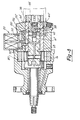
- the pump 10 includes a casing 12, which supports at one end thereof a drive shaft 14, the shaft 14 being adapted to be driven by the engine at one-half engine speed.
- the interior of the housing 12 is formed as a cavity 16 which houses a timing and metering assembly 18, the timing and metering assembly being controlled by means of an electromagnetic control valve 20.
- the timing and metering assembly 18 is rotated by the shaft 14, as is a vane transfer pump 22 which is mounted at the opposite end of the housing relative to the shaft 14.
- the pump 22 is utilized to pressurize the supply fuel for the operation of the timing and metering assembly 18.
- the shaft 14 is mounted for rotation within the housing 12 and supported therein by means of a bearing 26.
- the shaft 14 is rigidly connected to the timing and metering assembly 18 such that the timing and metering assembly 18 is rotated by rotation of the shaft 14.
- the timing and metering assembly 18 is rotatably supported in a tubular sleeve 30, the sleeve 30 being press-fitted into the housing 12.
- the assembly 18 includes a timing and metering cylinder 32, in which are formed the various cavities and passages to perform the control functions to be described.
- the vane transfer pump 22 receives fuel from a source connected to a housing member 34, the pump 22 being formed as a vane pump, see Figure 1 a, and it functions to pressurize the fuel within the housing 34.
- This pressurized fuel is fed to a supply passageway 38 formed in the sleeve 30 and the housing 12.
- the supply fuel is fed by means of passage 38 to a supply annulus 40 which is formed on the inside surface of the housing 12.
- the supply fuel in annulus 40 is, in turn, in fluid communication with the interior of the control solenoid 20 by means of a passageway 42.
- the control solenoid 20 is adapted to be controlled by energizing the coil 46, the coil 46 controlling the position of an armature 48.
- the movement of the armature 48 controls a three way valve arrangement which includes a first valve 52 which will be seen to control the flow of fuel to the timing chamber and a second valve 50 controlling the flow of fuel to the metering chamber.
- the solenoid assembly 20 is mounted in an aperture through the housing and a second aperture formed in the sleeve 30.
- the solenoid may be mounted in any conventional fashion.
- the central portion of the cylinder 32 is formed with a metering chamber 60 and a timing chamber 62, the chambers 60 and 62 being separated by means of a free or floating piston 64.
- the timing chamber 62 is in fluid communication with opposing faces of a pair of pumping plungers 66, 68.
- the pumping plungers 66,, 68 are telescopically mounted within a passageway 70 formed in the cylinder 32. Pressurized fluid from the timing chamber 62 is fed to the opposing faces of plungers 66, 68 by means of a passageway 72.
- plungers 66, 68 Upon pressurization of passageway 72, plungers 66, 68 are forced radially outwardly to precisely position a roller 74 associated with plunger 66 and a second roller 76 associated with plunger 68. Plungers 66, 68 act to move the rollers 74, 76 through a pair of shoes 75, 77 disposed therebetween.
- the rollers 74, 76 are positioned to engage a preselected position of a cam lobe formed on the interior face of a cam element 80, which cam element may be press-fitted into the housing 12.
- the cam surface on the interior of cam element 80 operate on rollers 74, 76 to, in turn, force plungers 66, 68 radially inwardly and thereby increase the pressure within the timing chamber 62.
- the vane transfer pump pressurizes the source of fluid within housing 34 and provides this pressurized fluid to a supply annulus 40 through a passageway 38.
- the view of the pump in Figure 1, as stated above, is shown in metering portion of the control cycle.
- the low pressure valve (second valve) 50 is open or unseated and the high pressure valve (first valve) 52 is closed or seated.
- the supply fluid at annulus 40 is provided to the interior of the solenoid 20 and, through passage 42, to a metering annulus 84.
- the pressurized fluid at metering annulus 84 is fed through a passageway 86 in sleeve 30 to a metering passageway 88.
- the metering passageway 88 is in fluid communication with the metering annulus 84 by means of connecting passageway 86.
- this pressurized fluid with the solenoid 20 energized in the state shown, will cause fluid to be metered into the metering chamber 60 and force the floating piston 64 to the left.
- This metering will continue as long as the control valve 20 is in the energized state and the metering passageway 88 is in fluid communication with the matering inlet passageway 86.
- the metering inlet passageway 86 is positioned to provide sufficient time to meter the desired amount of fuel into the metering chamber 60.
- valve 20 Upon the completion of metering the desired amount of fuel into the metering chamber 60, the valve 20 is de-energized as will be seen from a description of Figure 2.
- the vane transfer pump is an eccentric center pump which includes a plurality of vanes 90 which are positioned at 90 degrees one relative to the others. As seen from Figure 1 a, the chambers formed between adjacent vanes 90 will become smaller in volume as the shaft is rotated. Thus, the fluid is pressurized within the chambers.
- FIG. 1b there is illustrated an unwrapped view of the distributor sleeve in the area of passageway 86.
- the metering inlet passageway 86 is illustrated on the sleeve 30 through which the fuel is fed to the metering chamber. It is to be understood that the position and configuration of the inlet metering passageways 86 can be modified to accommodate the particular operation of the pump when associated with a particular engine.
- the circular ports 102 shown are delivery ports which, as will be explained hereinafter, are utilized to supply fuel from the metering chamber to the engine during injection.
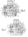
- FIG. 2 there is illustrated the premetering of fuel into the timing chamber 62.
- the low pressure valve 50 is closed and the high pressure valve 52 is open.
- the fuel supply at supply annulus 40 which is fed to the interior of the solenoid 20 is permitted to flow past the high pressure seat associated with valve 52 to a timing chamber fill annulus 92.
- Pressurized fuel in the fill annulus 92 is fed to the timing chamber 62 and also, by means of passageway 72, to the opposing faces of plungers 66, 68.
- the pressurized fuel forces the plunger 66, 68 and the associated rollers 74, 76 outwardly toward a predetermined position which is determined by the duration of de-energization of the valve in the position shown in Figure 2. It is to be understood that the low pressure valve 50 is closed and therefore fuel from the metering chamber cannot be forced out of the metering chamber in response to the pressure being built on the timing side of the floating piston 64.
- FIG. 4 there is illustrated the injection portion of the fuel control cycle wherein the high pressure valve 52 is shown in the closed position.
- the timing chamber is hydraulically closed to preclude fluid from flowing from the timing chamber to the supply annulus 40 through the high pressure seat associated with valve 52.
- the cam 80 forces plunger 66, 68 radially inwardly through rollers 74, 76. This pressurizes the fluid in timing chamber 62 and forces the floating piston 64 to the right. This movement of the floating piston 64 pressurizes the metering chamber 60 thereby forcing the fuel out of metering chamber 60 to a discharge connection at threaded portion 100 by means of passageway 88 and a delivery port passage 102 formed in the sleeve 30.
- the communication between passage 88 and passage 102 is created by rotation of the core cylinder 32.
- the fact that low pressure valve 50 is open is of no consequence as the communication between metering chamber 60 and metering inlet passageway 86 is terminated due to this same rotation.
- FIG. 5 there is illustrated the final or end of injection portion of the control cycle.
- the pressurized fuel is dumped back to the supply.
- the high pressure valve 52 is closed and the low pressure valve 50 is open.
- the floating piston 64 travels sufficiently to cause passage 106 to align with dump ports 107, 109 in core cylinder 32, the pressure in timing chamber 62 is vented back to supply via passageway 108.
- passage 106 is aligned with ports 107, 109, further displacement of plungers 66, 68 simply dump additional fuel back to the supply circuit.
- the floating piston 64 stops displacing fluid out of the metering chamber 60, and the injection event is terminated.
- the assembly has returned to the position shown in Figure 1 and is now ready for the next fuel control cycle.
- FIG. 6 there is illustrated a schematic diagram of the hydraulic circuit associated with the transfer pump and the floating piston.
- a spring 112 which is utilized to bias the floating piston 64 to the left as shown in the diagram of Figure 6. Accordingly, when the engine is shut down and the pump 22 is not pressurizing the system, the piston 64 will position itself to the left in the chamber 114. During initial cranking of the engine, there is insufficient pressure to move the piston 64 to the right to create a normal operation situation. Accordingly, a by-pass passageway 116 is provided from the outlet of the pump 22 to the interior of cavity 114.
- the passageway 116 is open to the interior of the cavity and the passage 118 is covered by piston 64.
- the system normally in- dudes a fuel pump (not shown) which feed the inlet of transfer pump 22.
- the pressure from this fuel pump is fed to a line 120 through the interior of cavity 114 and through passage 116 to the outlet side of the transfer pump 22.
- the normal fuel pump will purge and charge the lines connected to the outlet of pump 22.
- the piston After sufficient cranking has occurred to build up the pressure at the outlet side of pump 22, the piston will be forced to the right to cover the passage 116 and uncover passage 118. The piston will then react in a normal modulating manner.
- FIG. 7 there is illustrated a composite graph illustrating the pump piston position and the control valve energization state relative to engine crank angle.
- the pump pistons 66, 68 positions relative to the cam profile are illustrated.
- the cam profile is shown as the dotted line 130 while the position of the pump pistons 66, 68 are shown as solid line 132. It is seen that the position of the piston departs from the cam profile, the departure varying depending on the degree to which the pistons are forced radially outwardly by the pressurization of the timing chamber.
- time A shown in Figure 7 the metering chamber is being premetered with fuel in accordance with the operation described in conjunction with Figure 1-5.
- portion B of curve 132 the timing chamber is being premetered with fuel to position pistons 66, 68 and the piston follow the position shown.
- the pump piston position curve 132 departs from the dotted cam profile 130 to remain at the preselected position.
- the pumping pistons then following the position of the cam profile (position C). This occurs at injection.
- the middle curve is the position of the floating piston and it is seen that during metering, portion A of curve 132, which corresponds to portion D of the middle curve, the piston is moved to a preselected position depending on how much fuel is metered into the metering chamber 60.
- portion B of curve 132 the floating piston assumes the position shown at E and remains there during the time of portion B of curve 132 and also the time that curve 132 departs from curve 130. This is shown as position E in the middle graph.
- the piston is returned to its original position and follows the portion F of the middle curve.
- the control valve is energized, shown by level G of the lower curve, during the premetering of the metering chamber.
- the control valve is de-energized (portion H).
- portion H When the curve at 132 departs from curve 130, the holding portion of the curve, the solenoid is again energized as shown by the rise to the level I at the lower end of Figure 7.
- Figure 8 the configuration of Figure 8 is substantially identical to the configuration illustrated in Figures 1-5 with exceptions to be noted below.
- the major change involves the addition of a check valve 150 in the output passageway from the control valve 20, the addition of a metering annulus 152 and a provision of a passageway 156 which is in fluid communication between the cavity supporting the valve 150 and the metering annulus 152.
- low pressure valve 50 is open and high pressure valve 52 is closed as was the case with Figure 1.
- the passage 156 is devised such that as soon as the injection portion of the previous cycle is completed, the passage 156 is in fluid communication with the cavity supporting check valve 150 and the metering annulus 152. In this way, metering of fuel into the metering chamber 60 may start in response to the operation of the control valve 20 without waiting for the metering inlet slot to be in fluid communication with the passage 88.
- Figure 8 involves real time metering of the timing chamber 62 and there is no control of the ultimate position of piston 66, 68.
- the pistons 66, 68 are forced, through pressurization of timing chambers 62, to the extreme position wherein they are always in contact with the cam face of cam member 80.
Landscapes
- Engineering & Computer Science (AREA)
- Chemical & Material Sciences (AREA)
- Combustion & Propulsion (AREA)
- Mechanical Engineering (AREA)
- General Engineering & Computer Science (AREA)
- Fuel-Injection Apparatus (AREA)
- Lubrication Of Internal Combustion Engines (AREA)
- Control Of The Air-Fuel Ratio Of Carburetors (AREA)
Claims (4)
Priority Applications (1)
| Application Number | Priority Date | Filing Date | Title |
|---|---|---|---|
| AT81402000T ATE10300T1 (de) | 1980-12-17 | 1981-12-15 | Verteilerpumpe mit durch einzelventil gesteuertem freikolben. |
Applications Claiming Priority (2)
| Application Number | Priority Date | Filing Date | Title |
|---|---|---|---|
| US06/217,296 US4453896A (en) | 1980-12-17 | 1980-12-17 | Distributor pump with floating piston single control valve |
| US217296 | 1994-03-23 |
Publications (2)
| Publication Number | Publication Date |
|---|---|
| EP0055171A1 EP0055171A1 (fr) | 1982-06-30 |
| EP0055171B1 true EP0055171B1 (fr) | 1984-11-14 |
Family
ID=22810460
Family Applications (1)
| Application Number | Title | Priority Date | Filing Date |
|---|---|---|---|
| EP81402000A Expired EP0055171B1 (fr) | 1980-12-17 | 1981-12-15 | Pompe distributrice ayant un piston libre commandé par une valve unique |
Country Status (8)
| Country | Link |
|---|---|
| US (1) | US4453896A (fr) |
| EP (1) | EP0055171B1 (fr) |
| JP (1) | JPS57124072A (fr) |
| AT (1) | ATE10300T1 (fr) |
| BR (1) | BR8108164A (fr) |
| CA (1) | CA1178486A (fr) |
| DE (1) | DE3167235D1 (fr) |
| ES (1) | ES508049A0 (fr) |
Families Citing this family (16)
| Publication number | Priority date | Publication date | Assignee | Title |
|---|---|---|---|---|
| US4418867A (en) * | 1982-04-02 | 1983-12-06 | The Bendix Corporation | Electrically controlled unit injector |
| US4501244A (en) * | 1982-07-15 | 1985-02-26 | Lucas Industries Public Limited Company | Fuel injection pumping apparatus |
| JPS60209663A (ja) * | 1984-04-03 | 1985-10-22 | Nippon Denso Co Ltd | 燃料噴射ポンプ |
| DE3412834A1 (de) * | 1984-04-05 | 1985-10-24 | Robert Bosch Gmbh, 7000 Stuttgart | Kraftstoffeinspritzpumpe |
| GB8417862D0 (en) * | 1984-07-13 | 1984-08-15 | Lucas Ind Plc | Fuel pumping apparatus |
| US4671239A (en) * | 1984-07-17 | 1987-06-09 | Nippondenso Co., Ltd. | Fuel injection pump |
| DE3612942A1 (de) * | 1986-04-17 | 1987-10-22 | Bosch Gmbh Robert | Kraftstoffeinspritzpumpe fuer brennkraftmaschinen |
| US4757795A (en) * | 1986-04-21 | 1988-07-19 | Stanadyne, Inc. | Method and apparatus for regulating fuel injection timing and quantity |
| US5012785A (en) * | 1989-06-28 | 1991-05-07 | General Motors Corporation | Fuel injection delivery valve with reverse flow venting |
| DE3923271A1 (de) * | 1989-07-14 | 1991-01-24 | Bosch Gmbh Robert | Kraftstoffeinspritzeinrichtung fuer brennkraftmaschinen, insbesondere pumpeduese |
| US5099814A (en) * | 1989-11-20 | 1992-03-31 | General Motors Corporation | Fuel distributing and injector pump with electronic control |
| DE4315646A1 (de) * | 1993-05-11 | 1994-11-17 | Bosch Gmbh Robert | Kraftstoffeinspritzpumpe für Brennkraftmaschinen |
| DE4438251A1 (de) * | 1994-10-26 | 1996-05-02 | Bosch Gmbh Robert | Kraftstoffeinspritzpumpe |
| US5685275A (en) * | 1996-04-30 | 1997-11-11 | Stanadyne Automotive Corp. | Fuel injection pump with spill and line pressure regulating systems |
| DE19717494A1 (de) * | 1997-04-25 | 1998-10-29 | Bosch Gmbh Robert | Kraftstoffeinspritzpumpe der Verteilerbauart |
| DE10040522A1 (de) * | 2000-08-18 | 2002-02-28 | Bosch Gmbh Robert | Kraftstoffeinspritzsystem für Brennkraftmaschinen |
Family Cites Families (4)
| Publication number | Priority date | Publication date | Assignee | Title |
|---|---|---|---|---|
| GB949842A (en) * | 1960-08-09 | 1964-02-19 | Cav Ltd | Fuel pumps for internal combustion engines |
| GB1219765A (en) * | 1967-03-28 | 1971-01-20 | Cav Ltd | Liquid fuel injection pumping apparatus |
| GB1227332A (fr) * | 1967-05-23 | 1971-04-07 | ||
| JPS5756660A (en) * | 1980-09-22 | 1982-04-05 | Hitachi Ltd | Fuel injection pump |
-
1980
- 1980-12-17 US US06/217,296 patent/US4453896A/en not_active Expired - Lifetime
-
1981
- 1981-11-26 CA CA000391021A patent/CA1178486A/fr not_active Expired
- 1981-12-15 DE DE8181402000T patent/DE3167235D1/de not_active Expired
- 1981-12-15 EP EP81402000A patent/EP0055171B1/fr not_active Expired
- 1981-12-15 AT AT81402000T patent/ATE10300T1/de not_active IP Right Cessation
- 1981-12-16 BR BR8108164A patent/BR8108164A/pt unknown
- 1981-12-16 ES ES508049A patent/ES508049A0/es active Granted
- 1981-12-17 JP JP56202604A patent/JPS57124072A/ja active Pending
Also Published As
| Publication number | Publication date |
|---|---|
| ES8302205A1 (es) | 1982-12-16 |
| BR8108164A (pt) | 1982-09-28 |
| ES508049A0 (es) | 1982-12-16 |
| EP0055171A1 (fr) | 1982-06-30 |
| ATE10300T1 (de) | 1984-11-15 |
| CA1178486A (fr) | 1984-11-27 |
| JPS57124072A (en) | 1982-08-02 |
| US4453896A (en) | 1984-06-12 |
| DE3167235D1 (en) | 1984-12-20 |
Similar Documents
| Publication | Publication Date | Title |
|---|---|---|
| US4449507A (en) | Dual pressure metering for distributor pumps | |
| US4453896A (en) | Distributor pump with floating piston single control valve | |
| JP3889057B2 (ja) | 燃料噴射システム | |
| EP0050053B1 (fr) | Pompe d'injection de combustible pour commander la durée et le début d'injection | |
| US4351283A (en) | Diesel fuel injection pump secondary fuel metering control system | |
| JPH07122422B2 (ja) | 燃料噴射装置 | |
| US4625694A (en) | Fuel pumping apparatus | |
| US4445822A (en) | Injection pump | |
| JPH0370112B2 (fr) | ||
| US4426977A (en) | Dual solenoid distributor pump system | |
| US4019481A (en) | Fuel injection systems | |
| US4485789A (en) | Fuel injector with inner chamber vacuum | |
| US4418671A (en) | Dual solenoid distributor pump | |
| EP0068924A2 (fr) | Pompe d'injection de carburant | |
| US6152109A (en) | Liquid fuel injecting device for internal combustion engine | |
| EP0055653B1 (fr) | Pompe d'injection distributrice | |
| US3859972A (en) | Fuel injection system for an internal combustion engine | |
| CN1010336B (zh) | 柴油机的燃油喷射装置 | |
| US4446836A (en) | Fuel injection pumping apparatus | |
| GB2275307A (en) | I.c.engine high pressure distributor fuel injection system | |
| EP0136551B1 (fr) | Système d'injection de carburant à haute pression pour un moteur Diesel | |
| CA1170903A (fr) | Pompe distributrice a piston libre avec solenoide unique | |
| US4492534A (en) | Fuel injection pump for internal combustion engine | |
| US4449503A (en) | Fuel injection pump | |
| EP1171707B1 (fr) | Pompe d'alimentation variable et systeme de rampe d'injection a carburant utilisant celle-ci |
Legal Events
| Date | Code | Title | Description |
|---|---|---|---|
| PUAI | Public reference made under article 153(3) epc to a published international application that has entered the european phase |
Free format text: ORIGINAL CODE: 0009012 |
|
| 17P | Request for examination filed |
Effective date: 19811218 |
|
| AK | Designated contracting states |
Designated state(s): AT DE FR GB IT |
|
| ITF | It: translation for a ep patent filed | ||
| GRAA | (expected) grant |
Free format text: ORIGINAL CODE: 0009210 |
|
| AK | Designated contracting states |
Designated state(s): AT DE FR GB IT |
|
| REF | Corresponds to: |
Ref document number: 10300 Country of ref document: AT Date of ref document: 19841115 Kind code of ref document: T |
|
| REF | Corresponds to: |
Ref document number: 3167235 Country of ref document: DE Date of ref document: 19841220 |
|
| ET | Fr: translation filed | ||
| PLBE | No opposition filed within time limit |
Free format text: ORIGINAL CODE: 0009261 |
|
| STAA | Information on the status of an ep patent application or granted ep patent |
Free format text: STATUS: NO OPPOSITION FILED WITHIN TIME LIMIT |
|
| 26N | No opposition filed | ||
| PGFP | Annual fee paid to national office [announced via postgrant information from national office to epo] |
Ref country code: AT Payment date: 19891214 Year of fee payment: 9 |
|
| PG25 | Lapsed in a contracting state [announced via postgrant information from national office to epo] |
Ref country code: AT Effective date: 19901215 |
|
| PGFP | Annual fee paid to national office [announced via postgrant information from national office to epo] |
Ref country code: FR Payment date: 19901215 Year of fee payment: 10 |
|
| ITTA | It: last paid annual fee | ||
| PG25 | Lapsed in a contracting state [announced via postgrant information from national office to epo] |
Ref country code: FR Effective date: 19920831 |
|
| REG | Reference to a national code |
Ref country code: FR Ref legal event code: ST |
|
| PGFP | Annual fee paid to national office [announced via postgrant information from national office to epo] |
Ref country code: GB Payment date: 20001107 Year of fee payment: 20 |
|
| PGFP | Annual fee paid to national office [announced via postgrant information from national office to epo] |
Ref country code: DE Payment date: 20001222 Year of fee payment: 20 |
|
| PG25 | Lapsed in a contracting state [announced via postgrant information from national office to epo] |
Ref country code: GB Free format text: LAPSE BECAUSE OF EXPIRATION OF PROTECTION Effective date: 20011214 |
|
| REG | Reference to a national code |
Ref country code: GB Ref legal event code: PE20 Effective date: 20011214 |