EP0055415A1 - Anordnung eines Rotors und Methode zur Montage und Demontage einer Schaufel des Rotors - Google Patents
Anordnung eines Rotors und Methode zur Montage und Demontage einer Schaufel des Rotors Download PDFInfo
- Publication number
- EP0055415A1 EP0055415A1 EP81110424A EP81110424A EP0055415A1 EP 0055415 A1 EP0055415 A1 EP 0055415A1 EP 81110424 A EP81110424 A EP 81110424A EP 81110424 A EP81110424 A EP 81110424A EP 0055415 A1 EP0055415 A1 EP 0055415A1
- Authority
- EP
- European Patent Office
- Prior art keywords
- pin
- blade
- rotor
- base
- socket
- Prior art date
- Legal status (The legal status is an assumption and is not a legal conclusion. Google has not performed a legal analysis and makes no representation as to the accuracy of the status listed.)
- Granted
Links
- 238000000034 method Methods 0.000 title claims 9
- 238000003754 machining Methods 0.000 claims description 3
- 230000000712 assembly Effects 0.000 description 5
- 238000000429 assembly Methods 0.000 description 5
- 239000012530 fluid Substances 0.000 description 2
- 238000012986 modification Methods 0.000 description 2
- 230000004048 modification Effects 0.000 description 2
- 230000000295 complement effect Effects 0.000 description 1
- 230000000694 effects Effects 0.000 description 1
Images

Classifications
-
- F—MECHANICAL ENGINEERING; LIGHTING; HEATING; WEAPONS; BLASTING
- F01—MACHINES OR ENGINES IN GENERAL; ENGINE PLANTS IN GENERAL; STEAM ENGINES
- F01D—NON-POSITIVE DISPLACEMENT MACHINES OR ENGINES, e.g. STEAM TURBINES
- F01D5/00—Blades; Blade-carrying members; Heating, heat-insulating, cooling or antivibration means on the blades or the members
- F01D5/30—Fixing blades to rotors; Blade roots ; Blade spacers
- F01D5/32—Locking, e.g. by final locking blades or keys
- F01D5/326—Locking of axial insertion type blades by other means
-
- Y—GENERAL TAGGING OF NEW TECHNOLOGICAL DEVELOPMENTS; GENERAL TAGGING OF CROSS-SECTIONAL TECHNOLOGIES SPANNING OVER SEVERAL SECTIONS OF THE IPC; TECHNICAL SUBJECTS COVERED BY FORMER USPC CROSS-REFERENCE ART COLLECTIONS [XRACs] AND DIGESTS
- Y02—TECHNOLOGIES OR APPLICATIONS FOR MITIGATION OR ADAPTATION AGAINST CLIMATE CHANGE
- Y02T—CLIMATE CHANGE MITIGATION TECHNOLOGIES RELATED TO TRANSPORTATION
- Y02T50/00—Aeronautics or air transport
- Y02T50/60—Efficient propulsion technologies, e.g. for aircraft
-
- Y—GENERAL TAGGING OF NEW TECHNOLOGICAL DEVELOPMENTS; GENERAL TAGGING OF CROSS-SECTIONAL TECHNOLOGIES SPANNING OVER SEVERAL SECTIONS OF THE IPC; TECHNICAL SUBJECTS COVERED BY FORMER USPC CROSS-REFERENCE ART COLLECTIONS [XRACs] AND DIGESTS
- Y10—TECHNICAL SUBJECTS COVERED BY FORMER USPC
- Y10T—TECHNICAL SUBJECTS COVERED BY FORMER US CLASSIFICATION
- Y10T29/00—Metal working
- Y10T29/49—Method of mechanical manufacture
- Y10T29/49316—Impeller making
- Y10T29/49318—Repairing or disassembling
Definitions
- This invention generally relates to rotor assemblies, and more particularly to securing rotor blades within and removing rotor blades from rotor assemblies.
- a plurality of blades are secured to a rotor disc by axially sliding the blade roots into complementary slots or grooves formed in the disc. Because of this axial or side entry feature, blades of this type are commonly referred to as side entry blades. Once located within the rotor disc, the blades are then secured to the disc against axial movement, effectively locking the blades to the disc. To remove a blade, for example to repair or to replace the blade, the blade is first unlocked from the rotor disc to allow axial movement of the blade root, and then the root is slid out of the disc groove, freeing the blade from the disc.
- Prior art blade locking arrangements employed with rotor assemblies of the general type described above often involve considerable time or expense.
- the blade root structure is peened over the rotor disc slot. This, however, requires significant amounts of hand working and thus is costly and time consuming. Moreover, removal of the peened blade structure from the rotor disc may be difficult, entailing substantial time and effort.
- the blades are secured to the rotor disc by a plurality of locking pins, with each pin preventing axial movement of a selected blade and the pin itself held in place by an adjacent blade. With such an interrelated blade locking arrangement, often a plurality of blades must be removed from the rotor assembly in order to remove any one particular blade.
- the locking pin has an atypical shape or design and must be specifically manufactured just for one, specific type of rotor assembly.
- the present invention relates to a rotor assembly comprising a rotor disc and a plurality of rotor blades.
- the rotor disc defines a plurality of blade grooves, and includes a plurality of tenons disposed between the blade grooves and defining a plurality of pin sockets radially extending inward from outside surfaces of the tenons.
- Each rotor blade includes a root disposed within a blade groove to secure the blade against radial movement, and a blade platform overlaying a tenon and defining a radially extending pin aperture.
- the rotor assembly is characterized by a plurality of locking pins radially extending through the pin apertures and into the pin sockets to secure the rotor blades against axial movement, each locking pin including a head and a base to limit radial movement of the pin.
- the present invention relates to rotor assemblies. While the specific assembly herein described in detail is of the type usually employed in turbomachinery, it should be made clear that the present invention is not necessarily limited to this particular usage and is contemplated as having broader application.
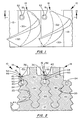
- Rotor assembly 10 generally including rotary support disc 12, a series of radially extending rotor blades or buckets 14 secured thereto, and a plurality of pins 16 which lock the rotor blades to the rotor disc.
- Rotor disc 12 defines a plurality of blade grooves or slots 20 and includes a plurality of tenons 22 which, in turn, define pin sockets 24.
- Rotor blades 14 comprise roots or stems 26, platforms 30, and airfoils 32, with the blade platforms defining pin apertures 34.
- Pins 16 include heads 36 and bases 40, and the base and head of each pin are spaced apart and connected together by stem 42.
- pins 16 may, and preferably do, comprise conventional, easily available rivets of the type wherein base 40 may be expanded by means of an internal break mandrel (not shown) secured within the base and extending upward therefrom through the interior of stem 42 and head 36 and to the exterior thereof.
- each blade groove 20 has a generally triangular form, and the surfaces defining the blade grooves include outwardly extending projections 44, forming what is generally referred to as a double dovetail or fir tree configuration.
- Tenons 22 are located between blade grooves 20 and define pin sockets 24, which radially extend inward from outside surfaces of the tenons.
- Roots 26 of rotor blades 14 have a cross-sectional shape complementing the fir tree configuration of blade grooves 20; and, in assembly, the blade roots are disposed within the blade grooves so that rotor disc 12 securely holds the rotor blades against radial movement. Roots 26 terminate in platforms 30, and airfoils 32 project outward therefrom to engage a working fluid flowing past rotor blades 14. Platforms 30 overlie the outside surface of disc 12 and are positioned so that pin apertures 34 extend over, and preferably are aligned with, pin sockets 24. As clearly shown in Figure 1, the axially extending side walls of each blade platform 30 span across rotor disc 12 generally parallel to the axis thereof, and preferably each side wall of a blade platform is adjacent to a side wall of a neighboring blade platform.
- pins 16 lock rotor blades 14 to disc 12. More specifically, stems 42 radially extend through pin apertures 34 and bases 40 extend into pin sockets 24. Axial movement of rotor blades 14 is limited by abutment of pin stems 42 with surfaces of the rotor blades defining pin apertures 34 and by abutment of pin bases 40 with surfaces of rotor disc 12 defining pin sockets 24. Preferably, stems 42 closely fit against surfaces of blade platforms 30 defining pin apertures 34, and bases 40 closely fit against surfaces of rotor disc tenons 22 defining pin sockets 24, substantially preventing axial movement of rotor blades 14 within rotor assembly 10.
- Heads 36 and bases 40 of pins 16 cooperate to secure the pins themselves in the locking position shown in Figure 2. That is, heads 36 project over radially outside surfaces 46 of blade platforms 30, limiting radially inward movement of pins 16; and bases 40, in assembly, project below radially inside surfaces 50 of the blade platforms, limiting radially outward movements of the pins. Preferably, heads 36 and bases 40 tightly fit against blade platforms 30, substantially preventing radial movement of pins 16. Also, heads 36 are preferably disposed within recessed portions 52 of surfaces 46, substantially eliminating any effects the pin heads might have on the aerodynamics of the fluid flow past blades 14.
- the distance (shown as length "A” in Figure 4) from the bottom of pin sockets 24 to inside surfaces 50 of blade platforms 30 is greater than the distance (shown as length "B” in Figure 4) between the bottom of pin bases 40 to the top of pin stems 42.
- blade root 26 is axially slid into blade groove 20.
- the blade is positioned with platform 30 extending over tenons 22, and specifically with pin aperture 34 aligned with pin socket 24.
- base 40 of pin 16 in an unexpanded position shown in Figure 3, the base is inserted in pin aperture 34.
- Pin 16 is moved radially inward until pin head 36 abuts against surface 46 of blade platform 30, bringing pin base 40 into pin socket 24.
- the pin base With base 40 extending into socket 26, the pin base is conventionally expanded by maintaining head 36 fixed and pulling upward on the previously mentioned internal break mandrel (not shown) extending from the interior of the pin base, upward through the pin head.
- head 36 of pin 16 is removed, preferably by machining off the head.
- drill 54 shown in Figure 4 may be used to mill off head 36. If drill 54 is utilized, preferably the diameter of the drill equals the diameter of pin aperture 34, inter alia, to eliminate or at least reduce any contact between the drill and the surfaces of blade platform 30 defining the pin aperture in case the drill is lowered below top surface 46 of the blade platform.
- stem 42 and base 40 of pin 16 are forced radially inward into pin socket 24 is radially below blade platform 30, unlocking blade 14 from rotor disc 12. With rotor blade 14 unlocked from rotor disc 12, the rotor blade is freed therefrom by axially sliding blade root 26 out of blade groove 20.
- any suitable means may be employed to force stem 42 radially inward into pin socket 24.
- threading tap 56 may be used first to form a threaded socket within pin stem 42 and then to push the stem into pin socket 24. If tap 56 is used via pin aperture 34 to force stem 42 into socket 24, the tap is removed from the pin aperture before blade 14 is slid out of disc 12.
- the width or diameter of pin socket 24 is greater than the width or diameter of pin aperture 34 to facilitate moving base 40 and stem 42 of pin 16 into the pin socket.
- pin stem 42 and pin base 40 are removed from the pin socket to prepare rotor assembly 10 either for the replacement of rotor blade 14 or to receive a new rotor blade. This may be done by simply pulling pin base 40 and pin stem 42 from pin socket 24.
- tap 56 may be reemployed to engage stem 42 and to pull the stem and base 40 from pin socket 24.
- Applicants have provided a unqiue rotor assembly 10 in which rotor blades 14 are securely locked in place in a very simple yet effective manner, requiring only inexpensive, easy to use, and readily available tools and equipment.
- it is not necessary, inter alia, to employ a locking pin having a peculiar, unique, or atypical shape. Further, it is not necessary to turn or rotate the locking pin itself into a locking position. This not only facilitates locking rotor blades 14 to disc 12 but also assists removing the rotor blades from the disc; and the blades may be removed from the rotor disc relatively quickly and easily, not requiring any special tools, extensive machining, or substantial amounts of labor. Moreover, all of the above advantages are accomplished while requiring access to only one side of the locking pin and while the locking pin is installed in an area of the rotor assembly where the stresses on the pin are relatively minor.
Landscapes
- Engineering & Computer Science (AREA)
- Mechanical Engineering (AREA)
- General Engineering & Computer Science (AREA)
- Turbine Rotor Nozzle Sealing (AREA)
Applications Claiming Priority (2)
| Application Number | Priority Date | Filing Date | Title |
|---|---|---|---|
| US221076 | 1980-12-29 | ||
| US06/221,076 US4400137A (en) | 1980-12-29 | 1980-12-29 | Rotor assembly and methods for securing a rotor blade therewithin and removing a rotor blade therefrom |
Publications (2)
| Publication Number | Publication Date |
|---|---|
| EP0055415A1 true EP0055415A1 (de) | 1982-07-07 |
| EP0055415B1 EP0055415B1 (de) | 1986-03-05 |
Family
ID=22826236
Family Applications (1)
| Application Number | Title | Priority Date | Filing Date |
|---|---|---|---|
| EP81110424A Expired EP0055415B1 (de) | 1980-12-29 | 1981-12-14 | Anordnung eines Rotors und Methode zur Montage und Demontage einer Schaufel des Rotors |
Country Status (4)
| Country | Link |
|---|---|
| US (1) | US4400137A (de) |
| EP (1) | EP0055415B1 (de) |
| JP (1) | JPS5925845B2 (de) |
| DE (1) | DE3174020D1 (de) |
Cited By (2)
| Publication number | Priority date | Publication date | Assignee | Title |
|---|---|---|---|---|
| DE3827036A1 (de) * | 1988-08-10 | 1990-02-15 | Man Energie Gmbh | Verfahren und vorrichtungen zum ausbauen von langen, aus zaehem werkstoff bestehenden innenkoerpern aus gebohrten elementen von schrumpfverbindungen |
| EP0340638B1 (de) * | 1988-05-03 | 1993-08-11 | Gec Alsthom Sa | Verfahren und Vorrichtung, zum Herausziehen der Pakete von Dampfturbinenschaufeln |
Families Citing this family (29)
| Publication number | Priority date | Publication date | Assignee | Title |
|---|---|---|---|---|
| US5318404A (en) * | 1992-12-30 | 1994-06-07 | General Electric Company | Steam transfer arrangement for turbine bucket cooling |
| US5713721A (en) * | 1996-05-09 | 1998-02-03 | General Electric Co. | Retention system for the blades of a rotary machine |
| US6287079B1 (en) * | 1999-12-03 | 2001-09-11 | Siemens Westinghouse Power Corporation | Shear pin with locking cam |
| DE10020229A1 (de) * | 2000-04-25 | 2001-10-31 | Alstom Power Nv | Verfahren und Vorrichtung zur Demontage einer Turbinenschaufel |
| US6499959B1 (en) * | 2000-08-15 | 2002-12-31 | General Electric Company | Steam turbine high strength tangential entry closure bucket and retrofitting methods therefor |
| US6389692B1 (en) * | 2000-12-15 | 2002-05-21 | General Electric Company | Method for removing stuck locking pin in turbine rotor |
| US6755618B2 (en) | 2002-10-23 | 2004-06-29 | General Electric Company | Steam turbine closure bucket attachment |
| EP2041398A2 (de) * | 2006-06-19 | 2009-04-01 | I.D.E. Technologies Ltd. | Rotor für verdichter |
| US8317481B2 (en) * | 2008-02-22 | 2012-11-27 | General Electric Company | Rotor of a turbomachine and method for replacing rotor blades of the rotor |
| US8240042B2 (en) * | 2008-05-12 | 2012-08-14 | Wood Group Heavy Industrial Turbines Ag | Methods of maintaining turbine discs to avert critical bucket attachment dovetail cracks |
| US8182230B2 (en) * | 2009-01-21 | 2012-05-22 | Pratt & Whitney Canada Corp. | Fan blade preloading arrangement and method |
| CN102405332A (zh) | 2009-02-20 | 2012-04-04 | 热力技术有限责任公司 | 热力能量发生系统 |
| US20100212316A1 (en) * | 2009-02-20 | 2010-08-26 | Robert Waterstripe | Thermodynamic power generation system |
| US8522552B2 (en) * | 2009-02-20 | 2013-09-03 | American Thermal Power, Llc | Thermodynamic power generation system |
| US8511991B2 (en) * | 2009-12-07 | 2013-08-20 | General Electric Company | Composite turbine blade and method of manufacture thereof |
| US9109450B2 (en) | 2012-06-14 | 2015-08-18 | United Technologies Corporation | Rotor assembly with interlocking tabs |
| US20140286782A1 (en) * | 2012-08-07 | 2014-09-25 | Solar Turbines Incorporated | Turbine blade staking pin |
| WO2014088673A2 (en) * | 2012-09-20 | 2014-06-12 | United Technologies Corporation | Gas turbine engine fan spacer platform attachments |
| CN105474373B (zh) * | 2013-08-16 | 2019-04-05 | 应用材料公司 | 用于半导体设备的密封槽方法 |
| US9382801B2 (en) * | 2014-02-26 | 2016-07-05 | General Electric Company | Method for removing a rotor bucket from a turbomachine rotor wheel |
| US20180073532A1 (en) * | 2016-09-12 | 2018-03-15 | Battelle Memorial Institute | System and process for joining dissimilar materials and solid-state interlocking joint with intermetallic interface formed thereby |
| US10544691B2 (en) * | 2018-01-04 | 2020-01-28 | Solar Turbines Incorporated | Staking tool assembly |
| JP6980587B2 (ja) | 2018-03-23 | 2021-12-15 | 株式会社東芝 | 電極、二次電池、電池パック、及び車両 |
| JP6937262B2 (ja) * | 2018-03-23 | 2021-09-22 | 株式会社東芝 | 活物質、電極、二次電池、電池パック、及び車両 |
| JP6892407B2 (ja) | 2018-03-23 | 2021-06-23 | 株式会社東芝 | 電極、二次電池、電池パック、及び車両 |
| JP7000223B2 (ja) | 2018-03-26 | 2022-01-19 | 株式会社東芝 | 活物質、活物質複合材料、電極、二次電池、電池パック及び車両 |
| JP7091202B2 (ja) | 2018-09-18 | 2022-06-27 | 株式会社東芝 | 活物質、電極、二次電池、電池パック、及び車両 |
| CN109895005B (zh) * | 2019-03-05 | 2021-06-18 | 中国科学院工程热物理研究所 | 一种用于转子榫连接装配的锁销预装配工装结构 |
| CN114810220B (zh) * | 2021-01-29 | 2024-02-20 | 中国航发商用航空发动机有限责任公司 | 航空发动机 |
Citations (9)
| Publication number | Priority date | Publication date | Assignee | Title |
|---|---|---|---|---|
| US2753149A (en) * | 1951-03-30 | 1956-07-03 | United Aircraft Corp | Blade lock |
| FR1121732A (fr) * | 1954-04-05 | 1956-08-24 | Thomson Houston Comp Francaise | Perfectionnement à la construction des roues de turbines |
| US2953348A (en) * | 1952-12-30 | 1960-09-20 | Gen Motors Corp | Blade fastenings |
| US3000614A (en) * | 1958-06-11 | 1961-09-19 | Gen Motors Corp | Rotor blade locks |
| US3001760A (en) * | 1959-08-07 | 1961-09-26 | Gen Motors Corp | Turbine blade lock |
| US3295826A (en) * | 1966-04-08 | 1967-01-03 | Gen Motors Corp | Blade lock |
| GB1339485A (en) * | 1971-08-09 | 1973-12-05 | Nevsky Mashinostroitelny Z Im | Turbine or compressor rotors |
| US3904317A (en) * | 1974-11-27 | 1975-09-09 | Gen Electric | Bucket locking mechanism |
| US3930751A (en) * | 1974-07-05 | 1976-01-06 | Carrier Corporation | Bucket locking mechanism |
Family Cites Families (5)
| Publication number | Priority date | Publication date | Assignee | Title |
|---|---|---|---|---|
| US2108435A (en) * | 1935-06-12 | 1938-02-15 | B F Sturtevant Co | Fan |
| US3165294A (en) * | 1962-12-28 | 1965-01-12 | Gen Electric | Rotor assembly |
| US3199836A (en) * | 1964-05-04 | 1965-08-10 | Gen Electric | Axial flow turbo-machine blade with abrasive tip |
| US3846041A (en) * | 1972-10-31 | 1974-11-05 | Avco Corp | Impingement cooled turbine blades and method of making same |
| US4046488A (en) * | 1975-11-07 | 1977-09-06 | Wickham Robert G | Radiator cooling fan |
-
1980
- 1980-12-29 US US06/221,076 patent/US4400137A/en not_active Expired - Lifetime
-
1981
- 1981-12-14 EP EP81110424A patent/EP0055415B1/de not_active Expired
- 1981-12-14 DE DE8181110424T patent/DE3174020D1/de not_active Expired
- 1981-12-17 JP JP56202618A patent/JPS5925845B2/ja not_active Expired
Patent Citations (10)
| Publication number | Priority date | Publication date | Assignee | Title |
|---|---|---|---|---|
| US2753149A (en) * | 1951-03-30 | 1956-07-03 | United Aircraft Corp | Blade lock |
| US2953348A (en) * | 1952-12-30 | 1960-09-20 | Gen Motors Corp | Blade fastenings |
| FR1121732A (fr) * | 1954-04-05 | 1956-08-24 | Thomson Houston Comp Francaise | Perfectionnement à la construction des roues de turbines |
| US2843356A (en) * | 1954-04-05 | 1958-07-15 | Gen Electric | Turbo-machine rotor assembly |
| US3000614A (en) * | 1958-06-11 | 1961-09-19 | Gen Motors Corp | Rotor blade locks |
| US3001760A (en) * | 1959-08-07 | 1961-09-26 | Gen Motors Corp | Turbine blade lock |
| US3295826A (en) * | 1966-04-08 | 1967-01-03 | Gen Motors Corp | Blade lock |
| GB1339485A (en) * | 1971-08-09 | 1973-12-05 | Nevsky Mashinostroitelny Z Im | Turbine or compressor rotors |
| US3930751A (en) * | 1974-07-05 | 1976-01-06 | Carrier Corporation | Bucket locking mechanism |
| US3904317A (en) * | 1974-11-27 | 1975-09-09 | Gen Electric | Bucket locking mechanism |
Cited By (3)
| Publication number | Priority date | Publication date | Assignee | Title |
|---|---|---|---|---|
| EP0340638B1 (de) * | 1988-05-03 | 1993-08-11 | Gec Alsthom Sa | Verfahren und Vorrichtung, zum Herausziehen der Pakete von Dampfturbinenschaufeln |
| DE3827036A1 (de) * | 1988-08-10 | 1990-02-15 | Man Energie Gmbh | Verfahren und vorrichtungen zum ausbauen von langen, aus zaehem werkstoff bestehenden innenkoerpern aus gebohrten elementen von schrumpfverbindungen |
| US5022136A (en) * | 1988-08-10 | 1991-06-11 | Gec Alsthom Sa | Method and a device for removing an elongate shrink-fitted core made of a tough material from a hole |
Also Published As
| Publication number | Publication date |
|---|---|
| JPS5925845B2 (ja) | 1984-06-21 |
| US4400137A (en) | 1983-08-23 |
| JPS57124004A (en) | 1982-08-02 |
| DE3174020D1 (en) | 1986-04-10 |
| EP0055415B1 (de) | 1986-03-05 |
Similar Documents
| Publication | Publication Date | Title |
|---|---|---|
| US4400137A (en) | Rotor assembly and methods for securing a rotor blade therewithin and removing a rotor blade therefrom | |
| US4451959A (en) | Methods for securing a rotor blade within a rotor assembly and removing a rotor blade therefrom | |
| US4684325A (en) | Turbomachine rotor blade fixings and method for assembly | |
| US4818182A (en) | System for locking turbine blades on a turbine wheel | |
| US7040866B2 (en) | System for retaining an annular plate against a radial face of a disk | |
| US3904317A (en) | Bucket locking mechanism | |
| US3088708A (en) | Compressor blade locking device | |
| US6477916B2 (en) | Methods of installing a balance weight for a rotary component in turbomachinery | |
| EP1348066B1 (de) | Verfahren zum zusammenbau von integralen axial eingeschobenen rotorschaufeln | |
| US7921556B2 (en) | Fully bladed closure for tangential entry round skirt dovetails | |
| US3395891A (en) | Lock for turbomachinery blades | |
| CA2226167C (en) | Apparatus and method for locking blades into a rotor | |
| CA1170987A (en) | Casing scraper and method for making the same | |
| KR102170572B1 (ko) | 터보기계 로터 조립체 및 방법 | |
| US2931625A (en) | Compressor rotor | |
| US8591192B2 (en) | Turbomachine rotor assembly and method | |
| EP1111193B1 (de) | Axiale Schaufelverriegelung für Turbomaschinen | |
| US4820127A (en) | Blade support and blade assembly | |
| US4711007A (en) | Method and apparatus for installing free standing turbine blades | |
| US6893224B2 (en) | Methods and apparatus for assembling turbine engines | |
| US4781532A (en) | Blade retention feature for saddle fir tree root blades of turbo machines and method of using same | |
| US6755618B2 (en) | Steam turbine closure bucket attachment | |
| US6761537B1 (en) | Methods and apparatus for assembling turbine engines | |
| US4797065A (en) | Turbine blade retainer | |
| DE69525014T2 (de) | Abdeckstück zur Abdichtung des Raums zwischen Rotorstufen |
Legal Events
| Date | Code | Title | Description |
|---|---|---|---|
| PUAI | Public reference made under article 153(3) epc to a published international application that has entered the european phase |
Free format text: ORIGINAL CODE: 0009012 |
|
| AK | Designated contracting states |
Designated state(s): CH DE GB IT LI NL |
|
| 17P | Request for examination filed |
Effective date: 19821227 |
|
| GRAA | (expected) grant |
Free format text: ORIGINAL CODE: 0009210 |
|
| AK | Designated contracting states |
Kind code of ref document: B1 Designated state(s): CH DE GB IT LI NL |
|
| ITF | It: translation for a ep patent filed | ||
| REF | Corresponds to: |
Ref document number: 3174020 Country of ref document: DE Date of ref document: 19860410 |
|
| PLBE | No opposition filed within time limit |
Free format text: ORIGINAL CODE: 0009261 |
|
| STAA | Information on the status of an ep patent application or granted ep patent |
Free format text: STATUS: NO OPPOSITION FILED WITHIN TIME LIMIT |
|
| 26N | No opposition filed | ||
| ITTA | It: last paid annual fee | ||
| PGFP | Annual fee paid to national office [announced via postgrant information from national office to epo] |
Ref country code: DE Payment date: 20001211 Year of fee payment: 20 |
|
| PGFP | Annual fee paid to national office [announced via postgrant information from national office to epo] |
Ref country code: GB Payment date: 20001213 Year of fee payment: 20 |
|
| PGFP | Annual fee paid to national office [announced via postgrant information from national office to epo] |
Ref country code: CH Payment date: 20001215 Year of fee payment: 20 |
|
| PGFP | Annual fee paid to national office [announced via postgrant information from national office to epo] |
Ref country code: NL Payment date: 20001231 Year of fee payment: 20 |
|
| PG25 | Lapsed in a contracting state [announced via postgrant information from national office to epo] |
Ref country code: LI Free format text: LAPSE BECAUSE OF EXPIRATION OF PROTECTION Effective date: 20011213 Ref country code: GB Free format text: LAPSE BECAUSE OF EXPIRATION OF PROTECTION Effective date: 20011213 Ref country code: CH Free format text: LAPSE BECAUSE OF EXPIRATION OF PROTECTION Effective date: 20011213 |
|
| PG25 | Lapsed in a contracting state [announced via postgrant information from national office to epo] |
Ref country code: NL Free format text: LAPSE BECAUSE OF EXPIRATION OF PROTECTION Effective date: 20011214 |
|
| REG | Reference to a national code |
Ref country code: GB Ref legal event code: PE20 Effective date: 20011213 |
|
| REG | Reference to a national code |
Ref country code: CH Ref legal event code: PL |
|
| NLV7 | Nl: ceased due to reaching the maximum lifetime of a patent |
Effective date: 20011214 |