EP0055422B1 - Dispositif pour dérouler et découper une bande de matériau - Google Patents
Dispositif pour dérouler et découper une bande de matériau Download PDFInfo
- Publication number
- EP0055422B1 EP0055422B1 EP81110490A EP81110490A EP0055422B1 EP 0055422 B1 EP0055422 B1 EP 0055422B1 EP 81110490 A EP81110490 A EP 81110490A EP 81110490 A EP81110490 A EP 81110490A EP 0055422 B1 EP0055422 B1 EP 0055422B1
- Authority
- EP
- European Patent Office
- Prior art keywords
- shaft
- shaped bar
- leg
- bar
- legs
- Prior art date
- Legal status (The legal status is an assumption and is not a legal conclusion. Google has not performed a legal analysis and makes no representation as to the accuracy of the status listed.)
- Expired
Links
Images


Classifications
-
- B—PERFORMING OPERATIONS; TRANSPORTING
- B65—CONVEYING; PACKING; STORING; HANDLING THIN OR FILAMENTARY MATERIAL
- B65H—HANDLING THIN OR FILAMENTARY MATERIAL, e.g. SHEETS, WEBS, CABLES
- B65H16/00—Unwinding, paying-out webs
- B65H16/005—Dispensers, i.e. machines for unwinding only parts of web roll
-
- A—HUMAN NECESSITIES
- A47—FURNITURE; DOMESTIC ARTICLES OR APPLIANCES; COFFEE MILLS; SPICE MILLS; SUCTION CLEANERS IN GENERAL
- A47K—SANITARY EQUIPMENT; ACCESSORIES THEREFOR, e.g. TOILET ACCESSORIES
- A47K10/00—Body-drying implements; Toilet paper; Holders therefor
- A47K10/24—Towel dispensers; Toilet paper dispensers
- A47K10/32—Dispensers for paper towels or toilet paper
- A47K10/34—Dispensers for paper towels or toilet paper dispensing from a web, e.g. with mechanical dispensing means
- A47K10/38—Dispensers for paper towels or toilet paper dispensing from a web, e.g. with mechanical dispensing means the web being rolled-up
-
- A—HUMAN NECESSITIES
- A47—FURNITURE; DOMESTIC ARTICLES OR APPLIANCES; COFFEE MILLS; SPICE MILLS; SUCTION CLEANERS IN GENERAL
- A47K—SANITARY EQUIPMENT; ACCESSORIES THEREFOR, e.g. TOILET ACCESSORIES
- A47K10/00—Body-drying implements; Toilet paper; Holders therefor
- A47K10/24—Towel dispensers; Toilet paper dispensers
- A47K10/32—Dispensers for paper towels or toilet paper
- A47K10/34—Dispensers for paper towels or toilet paper dispensing from a web, e.g. with mechanical dispensing means
- A47K10/38—Dispensers for paper towels or toilet paper dispensing from a web, e.g. with mechanical dispensing means the web being rolled-up
- A47K10/40—Dispensers for paper towels or toilet paper dispensing from a web, e.g. with mechanical dispensing means the web being rolled-up with extensible or collapsible roll supports or roll spindles
-
- B—PERFORMING OPERATIONS; TRANSPORTING
- B65—CONVEYING; PACKING; STORING; HANDLING THIN OR FILAMENTARY MATERIAL
- B65H—HANDLING THIN OR FILAMENTARY MATERIAL, e.g. SHEETS, WEBS, CABLES
- B65H75/00—Storing webs, tapes, or filamentary material, e.g. on reels
- B65H75/02—Cores, formers, supports, or holders for coiled, wound, or folded material, e.g. reels, spindles, bobbins, cop tubes, cans, mandrels or chucks
- B65H75/04—Kinds or types
- B65H75/08—Kinds or types of circular or polygonal cross-section
Definitions
- the invention relates to a device for unrolling and separating material webs, in particular cleaning cloths made of single or multi-layer paper, which essentially consists of a tubular frame, a shaft for receiving the material web roll, and bearings for the shaft.
- Devices of this type have been in use for a long time, they essentially consist of two U-brackets which are connected to one another in an articulated manner, the U-brackets with their part connecting the legs standing on the floor and the legs of the two U-brackets crossed are.
- a shaft is usually mounted in this cross, which can be inserted into a roll of material web.
- the connection between the web of material web and the shaft can be made via inserts or cones engaging in a sleeve of the web of web of material, alternatively, the sleeve can be designed correspondingly.
- a support is also mounted on the U-brackets, which also serves as a knife holder, the knife resting on the roller.
- the relatively large and weighty castors are stored horizontally in the stands, some of which are also equipped with wheels and can therefore be moved in the operating room similar to a hand truck. A vertical arrangement of the rollers is not possible with these known stands.
- the present invention is therefore based on the object of creating a smaller, handy dispenser which is capable of working both in a horizontal and in a vertical position and in which the unwanted unrolling of a material web is reliably prevented in both arrangements.
- a device for unrolling and separating material webs in particular cleaning cloths made of single or multi-ply paper, which essentially consist of a tubular frame, a shaft for receiving the material web roll, and bearings for the shaft, with the characteristic feature that the tubular frame consists of two U-shaped brackets, the shortened leg of the large U-bracket is rigidly connected to the small U-bracket in the area of the web, which is offset by 90 degrees to the large U-bracket, and the large U-bracket in the central area of both Has leg bearing for receiving the shaft and the crossbar of the large U-bracket is provided with a pivoted pressure bracket, which is loaded by spring force in the direction of the shaft.
- This construction results in a stand that has three feet.
- the roller is mounted between the two legs of the large U-bracket and is prevented from unintentional unwinding by the spring-loaded pressure bracket, both in the vertical and in the horizontal position.
- the horizontal position can be made possible by rotating the stand by 90 degrees and then resting on the shortened leg of the large U-bracket and the two legs of the smaller U-bracket.
- the advantage of a construction that can be used both in a horizontal and in a vertical position is obvious, so that large designs are not necessary. It should only be pointed out that in the case of a vertical arrangement the space requirement is of course significantly less.
- An advantageous embodiment of the invention provides that holes are made in the legs of the large U-bracket as bearings for the shaft.
- the thru axle is guided through the holes in the legs and then through the hollow shaft, so that the hollow shaft is rotatably mounted on the thru axle.
- the material web roll can be mounted directly on the hollow shaft by means of cones and then the thru axle is inserted through the fully assembled unit, so that a quick connection between the holder and the material web roll is ensured.
- the shaft is provided with lugs, one of which is displaceable in the longitudinal direction against the pressure of a spring.
- lugs one of which is displaceable in the longitudinal direction against the pressure of a spring.
- An advantageous embodiment of the invention provides that the tubular frame with through in the region of the ends of the long legs of the U-bracket and in the upper region of the short leg is provided bore holes.
- the through holes have a double meaning. On the one hand, they enable direct attachment, ie screwing the tubular frame onto a wall or floor surface, so that the dispenser can be brought as a stationary device; swiveling is then no longer possible, on the other hand the through holes serve to accommodate rubber knobs, which allow a higher resistance to displacement of the dispenser when it is in a vertical position, and on the other hand it prevents scratching of the documents, e.g. a desk top .
- a further advantageous embodiment of the invention provides that the pressure bracket is arranged on a guide pin extending parallel to the web.
- An expedient alternative to the one-armed lever is to weld side boundaries, which are advantageously designed with a catch, to the U-bracket and to provide them with a hole through which a bolt can be inserted, which then serves as a guide bolt for the pressure bracket. In this case, too, it is possible to reposition the pressure bracket by pulling out the bolt, so that paper can be pulled off to the left or right.
- a further expedient embodiment of the invention provides that the pressure bracket consists of a section steel bent into an open T. It is readily possible to design the pressure bracket such that the end of the bracket resting on the material, that is to say the roll, is a flat steel, which can optionally be designed as a knife or tear-off rail. In addition to the fact that such designs usually appear quite bulky, this also results in an unnecessarily high weight of the construction, as well as a larger amount of material is required. Furthermore, there are several processing steps because the flat iron has to be connected to the web or the U-bracket via any connections.
- profile steel for example in the form of a round bar, but more appropriately in the form of a square bar with an edge length of 3 to 5 mm, on the one hand there is a considerable reduction in weight, and on the other hand this steel can be bent into any shape without any difficulties, so that it can be bent very quickly into an open T, and the two parallel leg ends of this T can also be provided with eyes which bend around the web of the U-bracket or the guide pin.
- a further advantage of this embodiment is obtained if, according to a further expedient embodiment of the invention, the pressure spring is arranged between the profile steel ends which form the web of the open T, the profile steel ends of the open T expediently resiliently against at least one fixed lateral on which Guide pin arranged, limit can be pressed with a notch.
- the arrangement of the pressure spring between the two profile steel ends results in a reduction in space requirement, i. H. that the parallel to the web extending guide pin only has to be relatively short, because of this brevity, the material of this bracket need only have a lower thickness, since it is only slightly loaded due to the short lever arm.
- the spring inserted between the profile steel ends not only serves as a pressure spring for the pressure bracket, but at the same time spreads the profile steel ends outwards, as a result of which they are pressed against both a fixed lateral and a releasable lateral boundary. At least one of these limits is provided with a catch into which the legs or at least one leg engages when the pressure bracket is lifted, as a result of which the spring force is released and the web of material web can be exchanged safely.
- An expedient embodiment of the invention provides that a stabilization is arranged in the foot region of the long leg or in the head region of the short leg of the large U-bracket.
- the stabilization consists of a flat steel, which is placed around the shank in the form of a clamp and then extends further outwards parallel to the end face of the material web roll, with it being provided in the middle of the clamp with a threaded bolt which is inserted into the through hole of the long one Leg of the large U-bracket inserted and can be attached here with a wing nut, for example.
- the larger contact surface with a horizontal arrangement of the unwinding device ensures that even with only a small number of layers on the material web roll le and therefore also the low weight of the complete unit, the unwinding device does not tip over when material is pulled off the roll.
- the same stabilization is used in the upper region of the short femoral neck, ie inserted and screwed when the unwinding device is to be used in a vertical position.
- a section steel bent into a rectangle can be used as stabilization, which is expediently bent analogously.
- a preferred embodiment of the invention provides that the tubular frame is divided in the region of the bottom of the U-bracket and is connected by a plug connection.
- the tubular frame is expediently provided with stub axles.
- the division of the tubular frame enables the entire construction to be carried out from only two parts, i. H. the area of the small U-bracket with a welded-on short leg and the area of the long leg, both parts being interrupted approximately in the middle and connected by a plug connection in the area of the web.
- there is a considerable space advantage in terms of the space required when packaging the unit i. H. that the packaging is practically reduced to half the size.
- Another advantage is the fact that the guide pin, which is used to hold the pressure bracket and the spring, can be supported on both sides, i. H.
- the stub axles carry cones, at least one of which is pressed into the sleeve of the web of material web by a compression spring.
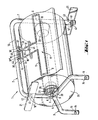
- the 1 and 2 consists of a large U-bracket 2 and a small U-bracket 3, the large U-bracket 2 having two legs 4, 7 of different lengths.
- the short leg 4 of the large U-bracket 2 is welded to the web 5 of the small U-bracket 3, so that there is a stand that has three feet.
- bores 8 are arranged which serve to receive a shaft 9.
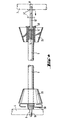
- the shaft 9 is as shown in FIGS. 2 and 4, designed as a hollow shaft and equipped with the cones 23.
- One cone is fixed in position on the shaft 9 by leg tension spring 28, the other either in the same way or by means of a fixed collar 48 on the hollow shaft 9 and both cones 23 engage in the sleeve 25 of the material web roll 26.
- the hollow shaft 9 is provided with projections 13, 13 ', of which the projection 13' is slidably mounted in the shaft 9 and is acted upon by a spring 14 via collar 14 '.
- the extension 13 ' By pressing in the extension 13 ', the entire length of the hollow shaft 9 can thus be reduced, i. H. that it can be inserted between the legs 4 and 7 of the U-bracket 2 and then, after relieving the spring 14 with the lugs 13, 13 ', fits into the bores 8, a stop washer axially defining the arrangement.
- Fig. 3 is an alternative embodiment of the tubular frame, in which the tubular frame 1 is divided in the area of the cross member 10 of the large U-bracket 2 and is connected by a plug connection 27.
- the plug connection 27 consists of a tubular pin 29 which engages in the opposite tube end 30 and is secured against rotation by a cam 32 arranged on a leaf spring 31 and engaging in a recess 33 in the socket of the tube end 30.
- the tubular frame 1 is provided with two stub axles 22, on each of which a cone 23 is arranged.
- the cone 23 In the area of the small U-bracket 3, the cone 23 is axially fixed, radially rotatable, whereas in the area of the long leg 7, the cone 23 can slide axially on the stub axle 22 and by a compression spring 24, which is between the cone 23 and the long leg 7 is arranged, is applied.
- the large U-bracket 2 is plugged together, that is to say when the pin 29 is inserted into the pipe end 30, the cam 32 engages in the recess 33, as a result of which the long leg 7 is mounted such that it cannot rotate and move.
- the cone 23 presses into the sleeve 25 of the material web roll 26, as a result of which the compression spring 24 is tensioned and the material web roll 26 comes into the correct position.
- the stabilizing tab 21 is normally made of flat steel with material bends 43 and provided with a bolt 41 which is guided through the through hole 16 'and here z. B. is attached via wing nut 42 when the tubular frame is arranged in a horizontal position (Fig. 1, right). In the case of a vertical arrangement (FIG. 2), the stabilizing layer 21 is fastened by means of the through hole 16 ′′. In this case, rubber buffers 34 are inserted into the holes 16 Stabilizing tab 21 rubber buffer provided, through which a firm stand of the trestle is guaranteed.
- the stub axle 12 extends through the hollow shaft 9, as can be seen in FIG. 2, and is provided on the opposite side with a wing nut 44 which prevents the stub axle 12 from falling out.
- the pressure bracket 11 is formed from a square steel and bent into an open T 17.
- the profile steel ends 18 are shaped into eyelets 46, between which the leg compression spring 19 is arranged.
- the leg compression spring 19 is supported against the crossbeam 10 of the large U-bracket 2 and engages a connection 45 between the profile steel ends 18 in order to press the pressure bracket 11 against the web roll 26.
- the connection 45 is preferably resiliently C-shaped.
- a leg 19 'of the leg compression spring 19 engages in this connection, while its second leg 19 "is supported on the crossmember 10.
- the profile steel ends 18 are made of a resilient material and press outwards, ie are under a certain prestress Eyelets 46 inserted over the guide pin 15, which extends parallel to the cross member 10 of the large U-bracket 2 and touch the fixed lateral boundary 20 on one side and the mountable stop 36 on the other. Both the stop 36 and the fixed lateral boundary 20 are included each provided a catch 35.
- the profiled steel ends 18 snap into these catches, ie they are first bent against each other when pulled up and then spring back outwards as soon as they have overcome the catches 35, so that the pressure bracket 11 now is held against the leg spring force above the material web roll 26. In this position it is possible to replace the web roll 26 without being hindered by the pressure bracket 11.
- the stop 36 is secured on the guide pin 15 by a self-locking fuse 37 against displacement by the profile steel ends 18. After removing the self-locking fuse 37, it is possible to remove the stop 36 and then pull the pressure bracket 11 with the pressure spring 19 arranged in between from the guide pin 15. By rotating the open T 17 together with the pressure spring 19 by 180 degrees, the pressure bracket 11 can be arranged in an arrangement offset by 180 degrees, that is to say on the other side of the material web roll 26, whereupon the stop 36 is then plugged in and the self-locking securing means 37 on the guide pin 15 are put on.
Landscapes
- Health & Medical Sciences (AREA)
- Public Health (AREA)
- Unwinding Webs (AREA)
- Perforating, Stamping-Out Or Severing By Means Other Than Cutting (AREA)
- Control And Other Processes For Unpacking Of Materials (AREA)
Claims (16)
Priority Applications (1)
| Application Number | Priority Date | Filing Date | Title |
|---|---|---|---|
| AT81110490T ATE13866T1 (de) | 1980-12-29 | 1981-12-16 | Vorrichtung zum abrollen und trennen von materialbahnen. |
Applications Claiming Priority (2)
| Application Number | Priority Date | Filing Date | Title |
|---|---|---|---|
| DE3049323A DE3049323C2 (de) | 1980-12-29 | 1980-12-29 | Vorrichtung zum Abrollen und Trennen von Materialbahnen |
| DE3049323 | 1980-12-29 |
Publications (3)
| Publication Number | Publication Date |
|---|---|
| EP0055422A2 EP0055422A2 (fr) | 1982-07-07 |
| EP0055422A3 EP0055422A3 (en) | 1983-04-13 |
| EP0055422B1 true EP0055422B1 (fr) | 1985-06-19 |
Family
ID=6120458
Family Applications (1)
| Application Number | Title | Priority Date | Filing Date |
|---|---|---|---|
| EP81110490A Expired EP0055422B1 (fr) | 1980-12-29 | 1981-12-16 | Dispositif pour dérouler et découper une bande de matériau |
Country Status (3)
| Country | Link |
|---|---|
| EP (1) | EP0055422B1 (fr) |
| AT (1) | ATE13866T1 (fr) |
| DE (1) | DE3049323C2 (fr) |
Families Citing this family (7)
| Publication number | Priority date | Publication date | Assignee | Title |
|---|---|---|---|---|
| DE8419633U1 (de) * | 1984-06-30 | 1984-09-27 | Hüdig und Rocholz GmbH & Co KG, 5620 Velbert | Abziehvorrichtung |
| DE3624655C2 (de) * | 1986-07-22 | 1993-11-25 | Feldmuehle Gmbh Scott | Vorrichtung zum Abrollen und Trennen von Materialbahnen |
| DE4004121A1 (de) * | 1990-02-10 | 1991-08-14 | Feldmuehle Gmbh Scott | Vorrichtung zum abrollen von materialbahnen |
| US5749539A (en) * | 1994-06-29 | 1998-05-12 | Ranpak Corp. | Dunnage-creating machine with plugless paper roll and method |
| FR2798919B1 (fr) * | 1999-09-27 | 2001-12-28 | Naturembal Sa | Dispositif de deroulement entre pointes |
| RU193028U1 (ru) * | 2019-07-19 | 2019-10-10 | Евгений Александрович Непокульчицкий | Держатель рулонной бумаги |
| CN113602911A (zh) * | 2021-07-23 | 2021-11-05 | 湖南印之明智能制造有限公司 | 一种柔性板材封胶装置 |
Family Cites Families (7)
| Publication number | Priority date | Publication date | Assignee | Title |
|---|---|---|---|---|
| US1341862A (en) * | 1919-02-24 | 1920-06-01 | Evan L Reed | Paper-roll support |
| DE510386C (de) * | 1928-04-19 | 1930-10-24 | Daniel Samain | Vorrichtung zum Abschneiden einzelner Bogen von Papierrollen |
| US1802251A (en) * | 1928-06-15 | 1931-04-21 | Max Breth | Unwinding device for bolts of cloth |
| US1891629A (en) * | 1931-12-05 | 1932-12-20 | Lester Van Wagner | Sanitary paper roll |
| FR2120597A5 (fr) * | 1971-01-07 | 1972-08-18 | Gallet Andre | |
| US3905532A (en) * | 1973-11-05 | 1975-09-16 | Bemiss Jason Corp | Holder for paper rolls |
| CH617118A5 (en) * | 1977-06-21 | 1980-05-14 | Karl Fuchs | Device for unrolling and cutting to length flat, web-like material |
-
1980
- 1980-12-29 DE DE3049323A patent/DE3049323C2/de not_active Expired
-
1981
- 1981-12-16 EP EP81110490A patent/EP0055422B1/fr not_active Expired
- 1981-12-16 AT AT81110490T patent/ATE13866T1/de not_active IP Right Cessation
Also Published As
| Publication number | Publication date |
|---|---|
| DE3049323A1 (de) | 1982-07-08 |
| EP0055422A2 (fr) | 1982-07-07 |
| EP0055422A3 (en) | 1983-04-13 |
| DE3049323C2 (de) | 1984-11-22 |
| ATE13866T1 (de) | 1985-07-15 |
Similar Documents
| Publication | Publication Date | Title |
|---|---|---|
| DE3337536C2 (fr) | ||
| DE3049323C2 (de) | Vorrichtung zum Abrollen und Trennen von Materialbahnen | |
| DE264297C (fr) | ||
| DE2817783A1 (de) | Einrichtung zum ausbreiten von rollen | |
| DE2529430C2 (de) | Demonstrationstafel (Flip-chart) | |
| DE2408247A1 (de) | Automatische oder halb-automatische betaetigungsvorrichtung, insbesondere fuer handbrausenkonsolen | |
| DE2559229C3 (de) | Stützfuß für Gerüste | |
| EP0170768A1 (fr) | Dispositif de distribution de matériaux enroulés | |
| DE2443042B2 (de) | Transportvorrichtung für Campingliegen | |
| EP1249192B1 (fr) | Chaise | |
| DE2815845A1 (de) | Vorrichtung zum leichteren loesen festsitzender radschrauben und -muttern | |
| DE29919446U1 (de) | Haltevorrichtung für eine Deckenrandschalung | |
| DE2939085A1 (de) | Vorrichtung zur krumpfbehandlung von gestrickschlaeuchen | |
| DE2919386C2 (de) | Gestell zur Aufnahme einer Putzmaterialrolle mit einem auf der Rolle aufliegenden Abreißmesser | |
| DE8803599U1 (de) | Rollstuhl mit einem auf den Boden absenkbaren Sitz | |
| DE2306932A1 (de) | Einbeinstativ | |
| CH637815A5 (en) | Work table with height adjustable table top | |
| DE1269522B (de) | Stuetzpfeiler fuer Schlingerschotten | |
| DE3418252C2 (de) | Kippbarer Ständer zur Halterung eines Friseurgerätes | |
| DE664651C (de) | Vorrichtung zum Ab- und Aufwickeln von Linoleumrollen u. dgl. | |
| DE10342328A1 (de) | Höhenverstellbarer Tapeziertisch | |
| DE3934918A1 (de) | Rundbreithalter | |
| DE8906470U1 (de) | Haltevorrichtung für eine in Form einer Rolle angeordnete Gewebebahn | |
| DE202010015434U1 (de) | Ankopplungsvorrichtung und medizinische Versorgungs- und/oder Transporteinrichtung mit Ankopplungsvorrichtung | |
| CH421820A (de) | Vorrichtung zum Stapeln und Transportieren von Gegenständen, mit selbsttätiger Höheneinstellung einer zum Aufnehmen von Gegenständen dienenden Trageinrichtung |
Legal Events
| Date | Code | Title | Description |
|---|---|---|---|
| PUAI | Public reference made under article 153(3) epc to a published international application that has entered the european phase |
Free format text: ORIGINAL CODE: 0009012 |
|
| AK | Designated contracting states |
Designated state(s): AT BE CH FR GB IT LU NL SE |
|
| PUAL | Search report despatched |
Free format text: ORIGINAL CODE: 0009013 |
|
| AK | Designated contracting states |
Designated state(s): AT BE CH FR GB IT LI LU NL SE |
|
| 17P | Request for examination filed |
Effective date: 19830221 |
|
| ITF | It: translation for a ep patent filed | ||
| GRAA | (expected) grant |
Free format text: ORIGINAL CODE: 0009210 |
|
| AK | Designated contracting states |
Designated state(s): AT BE CH FR GB IT LI LU NL SE |
|
| REF | Corresponds to: |
Ref document number: 13866 Country of ref document: AT Date of ref document: 19850715 Kind code of ref document: T |
|
| ET | Fr: translation filed | ||
| PG25 | Lapsed in a contracting state [announced via postgrant information from national office to epo] |
Ref country code: LU Free format text: LAPSE BECAUSE OF NON-PAYMENT OF DUE FEES Effective date: 19851231 |
|
| PLBE | No opposition filed within time limit |
Free format text: ORIGINAL CODE: 0009261 |
|
| STAA | Information on the status of an ep patent application or granted ep patent |
Free format text: STATUS: NO OPPOSITION FILED WITHIN TIME LIMIT |
|
| 26N | No opposition filed | ||
| PGFP | Annual fee paid to national office [announced via postgrant information from national office to epo] |
Ref country code: AT Payment date: 19861229 Year of fee payment: 6 |
|
| PGFP | Annual fee paid to national office [announced via postgrant information from national office to epo] |
Ref country code: NL Payment date: 19871231 Year of fee payment: 7 |
|
| ITTA | It: last paid annual fee | ||
| PGFP | Annual fee paid to national office [announced via postgrant information from national office to epo] |
Ref country code: CH Payment date: 19890317 Year of fee payment: 8 |
|
| PG25 | Lapsed in a contracting state [announced via postgrant information from national office to epo] |
Ref country code: GB Effective date: 19891216 Ref country code: AT Effective date: 19891216 |
|
| PG25 | Lapsed in a contracting state [announced via postgrant information from national office to epo] |
Ref country code: SE Effective date: 19891217 |
|
| PG25 | Lapsed in a contracting state [announced via postgrant information from national office to epo] |
Ref country code: LI Effective date: 19891231 Ref country code: CH Effective date: 19891231 Ref country code: BE Effective date: 19891231 |
|
| BERE | Be: lapsed |
Owner name: FELDMUHLE A.G. Effective date: 19891231 |
|
| PG25 | Lapsed in a contracting state [announced via postgrant information from national office to epo] |
Ref country code: NL Effective date: 19900701 |
|
| GBPC | Gb: european patent ceased through non-payment of renewal fee | ||
| NLV4 | Nl: lapsed or anulled due to non-payment of the annual fee | ||
| PG25 | Lapsed in a contracting state [announced via postgrant information from national office to epo] |
Ref country code: FR Effective date: 19900831 |
|
| REG | Reference to a national code |
Ref country code: CH Ref legal event code: PL |
|
| REG | Reference to a national code |
Ref country code: FR Ref legal event code: ST |
|
| EUG | Se: european patent has lapsed |
Ref document number: 81110490.0 Effective date: 19900829 |