EP0055478A1 - Sonnenwärmekollektor - Google Patents
Sonnenwärmekollektor Download PDFInfo
- Publication number
- EP0055478A1 EP0055478A1 EP81110760A EP81110760A EP0055478A1 EP 0055478 A1 EP0055478 A1 EP 0055478A1 EP 81110760 A EP81110760 A EP 81110760A EP 81110760 A EP81110760 A EP 81110760A EP 0055478 A1 EP0055478 A1 EP 0055478A1
- Authority
- EP
- European Patent Office
- Prior art keywords
- heat
- heat medium
- pipe
- medium pipe
- solar
- Prior art date
- Legal status (The legal status is an assumption and is not a legal conclusion. Google has not performed a legal analysis and makes no representation as to the accuracy of the status listed.)
- Granted
Links
- 239000007788 liquid Substances 0.000 claims abstract description 14
- 239000004020 conductor Substances 0.000 claims description 4
- 239000012530 fluid Substances 0.000 claims 1
- 238000010276 construction Methods 0.000 description 4
- 230000005494 condensation Effects 0.000 description 3
- 238000009833 condensation Methods 0.000 description 3
- 230000000694 effects Effects 0.000 description 3
- RYGMFSIKBFXOCR-UHFFFAOYSA-N Copper Chemical compound [Cu] RYGMFSIKBFXOCR-UHFFFAOYSA-N 0.000 description 2
- 229910052802 copper Inorganic materials 0.000 description 2
- 239000010949 copper Substances 0.000 description 2
- 230000008020 evaporation Effects 0.000 description 2
- 238000001704 evaporation Methods 0.000 description 2
- XLYOFNOQVPJJNP-UHFFFAOYSA-N water Substances O XLYOFNOQVPJJNP-UHFFFAOYSA-N 0.000 description 2
- 230000004907 flux Effects 0.000 description 1
- 239000011521 glass Substances 0.000 description 1
Images

Classifications
-
- F—MECHANICAL ENGINEERING; LIGHTING; HEATING; WEAPONS; BLASTING
- F24—HEATING; RANGES; VENTILATING
- F24S—SOLAR HEAT COLLECTORS; SOLAR HEAT SYSTEMS
- F24S10/00—Solar heat collectors using working fluids
- F24S10/40—Solar heat collectors using working fluids in absorbing elements surrounded by transparent enclosures, e.g. evacuated solar collectors
-
- F—MECHANICAL ENGINEERING; LIGHTING; HEATING; WEAPONS; BLASTING
- F24—HEATING; RANGES; VENTILATING
- F24S—SOLAR HEAT COLLECTORS; SOLAR HEAT SYSTEMS
- F24S10/00—Solar heat collectors using working fluids
- F24S10/90—Solar heat collectors using working fluids using internal thermosiphonic circulation
- F24S10/95—Solar heat collectors using working fluids using internal thermosiphonic circulation having evaporator sections and condenser sections, e.g. heat pipes
-
- Y—GENERAL TAGGING OF NEW TECHNOLOGICAL DEVELOPMENTS; GENERAL TAGGING OF CROSS-SECTIONAL TECHNOLOGIES SPANNING OVER SEVERAL SECTIONS OF THE IPC; TECHNICAL SUBJECTS COVERED BY FORMER USPC CROSS-REFERENCE ART COLLECTIONS [XRACs] AND DIGESTS
- Y02—TECHNOLOGIES OR APPLICATIONS FOR MITIGATION OR ADAPTATION AGAINST CLIMATE CHANGE
- Y02E—REDUCTION OF GREENHOUSE GAS [GHG] EMISSIONS, RELATED TO ENERGY GENERATION, TRANSMISSION OR DISTRIBUTION
- Y02E10/00—Energy generation through renewable energy sources
- Y02E10/40—Solar thermal energy, e.g. solar towers
- Y02E10/44—Heat exchange systems
Definitions
- This invention relates to a solar heat collector, and more particularly to improvements on the vapor condensing portion of a solar heat collector having a heat pipe and a solar heat collection-plate in an evacuated transparent housing.
- a solar heat collector using a heat pipe is constructed as follows A solar heat collection plate exposed to solar rays is disposed in an evacuated transparent pipe and contacts with the heat pipe which contains an evaporable working liquid and is connected to a heat releasing pipe.
- the heat releasing pipe communicates with the heat pipe and encloses a heat medium pipe so as to form an annular chamber.
- the heat collection plate heated by solar rays heats the evaporable working liquid in the heat pipe to evaporate it thereby producing vapor.
- the vapor rises upward in the heat pipe, reaches the annular chamber, and is cooled there by the heat meaduum pipe to condense .
- the condensate descends and its heated again.
- the heat medium pipe disclosed in the above- mentioned application seems to reduce the cross-sectional area of the passage for allowing the heat medium to flow by the corrugations . Therefore, it seems to prevent the whole construction from reducing the scale .
- An object of the invention is to provide a solar heat collector which can evaporate easily an evaporable working liquid in a heat pipe and condense rapidly the resultant vapor without making the construction for condensing the vapor large .
- Another object of the invention is to provide a solar heat collector which has a vapor condensing section of an excellent heat transfer characteristic and which can reduce the scale of the condensing section.
- the invention consists in that in a heat medium pipe of-the condensing section of a solar heat collector, heat releasing means is provided which extends in the longitudinal direction and has a plurality of fin portions extending from the inner face to a portion around the axis of the heat medium pipe, whereby heat of vapor surrounding the heat medium pipe is transmitted effectively to a heat medium in the heat medium pipe through heat conduction of the heat medium pipe and heat-conductive means .
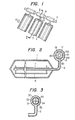
- the solar heat collector comprises a heat collection section exposed to solar rays (shown by an arrow) and a condensing section .
- the heat collection section there is an evacuated transparent pipe 1 of glass.
- a heat pipe 3 is disposed along the axis of the pipe 1 .
- the heat pipe is made of heat-conductive material such as copper and contains an eva p orable working liquid such as Fron R-113.
- the heat pipe 3 is fixed to a support 5 fitted in the evacuated transparent pipe 1 and one end portion thereof projects out of the pipe 1.
- a heat collection plate 7 is disposed in the pipe 1 so as to contact with the heat pipe 3 .
- a cylindrical casing 9 which is joined to the heat pipe 3 .
- the cylindrical casing 9 is closed at both ends in the longitudinal direction.
- a heat medium pipe 11 is disposed coaxially in the cylindrical casing 9, and supported by the end portions of the casing 9 so that a closed annular chamber 10 is formed.
- the chamber 10 surrounds the casing 9 and communicates with the heat pipe-3.
- a heat releasing member 13 which extends along the axis of the heat medium pipe 11 and has a plurality of, preferably six, hollow projections 130.
- the hollow projections 130 extend radially from the inner face to a portion around the axis of the- heat medium pipe 11 by more than about two thirds the radius of the pipe 11.
- Each of the hollow projections 130 comprises a pair of thin fin portions 131 joined to each other at the tips, and divides the interior of the heat medium pipe into a plurality of compartments 132, 133.
- the area of a compartment 132 defined by one of the hollow projections 130 is approximately equal to the area defined by two immediately adjacent projections 130.
- the heat releasing member 13 is made of a thin plate of heat conductive material such as copper and has twelve round portions so that there is no such an extremely narrow portion as would preventt the medium flow.
- a plurality of evacuated pipes 1, heat collection plates 7, heat pipes 3, and cylindrical casings 9 are provided, and the cylindrical casings 9 are axially arranged and mounted on the heat medium pipe 11, as shown in Fig. 1 .
- the heat collection plate 7 directed to the solar rays receives solar heat.
- the heat is transmitted to the working liquid in the heat pipe 3 through heat conduction to evaporate it.
- the resultant vapor of the working liquid rises in the heat pipe 3 and reaches the annular chamber 10.
- the vapor is cooled there by the heat medium pipe 11 to condense .
- the heat medium such as water in the heat medium pipe 11 is heated by heat of the vapor and the resultant condensate surrounding the heat medium pipe 11 through the wall of the heat medium pipe 11 and the heat releasing member 13 .
- the heat exchange between the working liquid vapor and the heat medium is effected.
- the condensate flows down and it is subjected to evaporation repeatedly.
- the heat medium pipe 11 is provided with the plurality of thin fin portions extending radially toward the axis portion .
- the thin fin portions are more crowded around the axis than near the inner face of the heat medium pipe 11 . Therefore, the thin fin portions make relatively even heat distribution in the heat medium pipe 11 , and reduce little the sectional area of the heat medium pipe 11 . Therefore, the heat transfer characteristic is remarkably improved.
- the heat medium pipe 11, further, does not have any fins on the outer surface, so that the chamber surrounding the heat medium pipe 11 can be reduced without restricting the evaporation of the working liquid.
- the header portion of the heat pipe 3 includes a cylindrical casing 30 and a heat medium pipe 31 .
- the heat medium pipe 31 has a saw-toothed outer surface which has a plurality of conical projections or saw-toothed fin 33, and a fin 35 inserted therein.
- the fin 35 has a crossed sectional shape defined by four thin plates extending radially from the central portion and extends in the longitudinal direction .
- the heat medium pipe 31 is divided into four compartments by the fin 35 .
- the heat transfer between the working liquid 32 and the heat medium 34 is so improved as will be described in the following.
- the condensation heat transfer illustrated in Fig. 5, wherein characteristic curves 51, 52 and 53 express the pipe 30 with the saw-toothed fins 33, a pipe with disc-like fins, and a flat pipe, respectively, is attained by using Fron R-113 as the working liquid at a condensation temperature of 50 °C and under a pressure of 1 .1 bar.
- the saw-toothed fins 33 have a heat transfer about twice as high as that of the disc-shaped fins.
- the heat transfer characteristics are remarkably improved, it is possible to curtail the length of the cylindrical casing portion, and as a result, it becomes possible to reduce the size of the heat exchange portion.
Landscapes
- Engineering & Computer Science (AREA)
- Physics & Mathematics (AREA)
- Life Sciences & Earth Sciences (AREA)
- Sustainable Development (AREA)
- Sustainable Energy (AREA)
- Thermal Sciences (AREA)
- Chemical & Material Sciences (AREA)
- Combustion & Propulsion (AREA)
- Mechanical Engineering (AREA)
- General Engineering & Computer Science (AREA)
- Photovoltaic Devices (AREA)
Applications Claiming Priority (2)
| Application Number | Priority Date | Filing Date | Title |
|---|---|---|---|
| JP188491/80 | 1980-12-29 | ||
| JP55188491A JPS57112657A (en) | 1980-12-29 | 1980-12-29 | Solar heat collector |
Publications (2)
| Publication Number | Publication Date |
|---|---|
| EP0055478A1 true EP0055478A1 (de) | 1982-07-07 |
| EP0055478B1 EP0055478B1 (de) | 1984-11-07 |
Family
ID=16224654
Family Applications (1)
| Application Number | Title | Priority Date | Filing Date |
|---|---|---|---|
| EP81110760A Expired EP0055478B1 (de) | 1980-12-29 | 1981-12-23 | Sonnenwärmekollektor |
Country Status (5)
| Country | Link |
|---|---|
| US (1) | US4440151A (de) |
| EP (1) | EP0055478B1 (de) |
| JP (1) | JPS57112657A (de) |
| AU (1) | AU550312B2 (de) |
| DE (1) | DE3167124D1 (de) |
Cited By (7)
| Publication number | Priority date | Publication date | Assignee | Title |
|---|---|---|---|---|
| EP0109716A1 (de) * | 1982-11-19 | 1984-05-30 | Koninklijke Philips Electronics N.V. | Sonnenkollektor-Anordnung |
| EP0095555A3 (de) * | 1982-05-29 | 1986-02-26 | Buderus Aktiengesellschaft | Vorrichtung zum Vorwärmen und/oder Verdampfen des Brennstoffes bei Ölbrennern |
| GB2194324A (en) * | 1986-08-08 | 1988-03-02 | Isoterix Limited | Heat pipes |
| GB2213258A (en) * | 1987-12-03 | 1989-08-09 | Hossein Valizadeh | Solar collectors |
| US6047697A (en) * | 1994-07-05 | 2000-04-11 | Energy International Systems Limited | Solar collector |
| WO2013013249A1 (en) * | 2011-07-22 | 2013-01-31 | Avagyan Yurik | Solar heat collector |
| WO2012171877A3 (de) * | 2011-06-14 | 2014-12-31 | Siemens Aktiengesellschaft | Solarthermische anlage mit wärmerohren |
Families Citing this family (8)
| Publication number | Priority date | Publication date | Assignee | Title |
|---|---|---|---|---|
| SE426342B (sv) * | 1982-04-23 | 1982-12-27 | Foerenade Fabriksverken | Anordning vid sjoforlagda rorvermevexlare for forankring av vermevexlaren vid sjons botten |
| WO1990004143A1 (en) * | 1988-10-03 | 1990-04-19 | Lasich John B | A system for heating fluid in process equipment with solar energy |
| US6059017A (en) * | 1998-04-20 | 2000-05-09 | The United States Of America As Represented By The Secretary Of The Navy | Directional heat exchanger |
| US20080047544A1 (en) * | 2006-07-24 | 2008-02-28 | Chong Han | Modular thermal radiation heating system |
| FR2942030B1 (fr) * | 2009-02-12 | 2012-10-19 | Sophia Antipolis En Dev | Ensemble de caloducs pour capteurs solaires |
| CN102878701A (zh) * | 2012-10-29 | 2013-01-16 | 安徽海太科新能源科技有限公司 | 蜗管式热管平板集热器 |
| CN103225916B (zh) * | 2013-04-22 | 2016-03-09 | 徐秀萍 | 工质高位集聚减压空晒保护金属热管真空集热装置 |
| CN120403091B (zh) * | 2025-06-18 | 2025-11-14 | 山西工大惠易能源科技有限公司 | 一种基于平板微热管的太阳能集热器 |
Citations (4)
| Publication number | Priority date | Publication date | Assignee | Title |
|---|---|---|---|---|
| US4059093A (en) * | 1975-09-22 | 1977-11-22 | Grumman Aerospace Corporation | Solar energy collector |
| GB2013870A (en) * | 1978-02-02 | 1979-08-15 | Philips Nv | Solar collector |
| US4217882A (en) * | 1978-10-30 | 1980-08-19 | Feldman Karl T Jr | Passive solar heat collector |
| DE3024475A1 (de) * | 1979-07-03 | 1981-01-22 | Philips Nv | Sonnenkollektor |
Family Cites Families (8)
| Publication number | Priority date | Publication date | Assignee | Title |
|---|---|---|---|---|
| US3799144A (en) * | 1972-03-21 | 1974-03-26 | Us Air Force | Solar heat source and receiver system |
| GB1533241A (en) * | 1975-01-20 | 1978-11-22 | Bennett C | Solar panels |
| US3983861A (en) * | 1975-08-21 | 1976-10-05 | Westman Manufacturing Company | Solar energy conversion device |
| JPS5255033A (en) * | 1975-10-31 | 1977-05-06 | Sharp Corp | Solar heat collecting apparatus |
| JPS54115439A (en) * | 1978-03-01 | 1979-09-08 | Shin Nippon Kuuchiyou Kk | Solar heat collector |
| NL7807174A (nl) * | 1978-06-30 | 1980-01-03 | Philips Nv | Zonnecollector met een verdampingscondensatiesysteem. |
| NL7907323A (nl) * | 1978-10-04 | 1980-04-09 | Alcoa Australia | Mantel voor een warmte-uitwisselaar. |
| JPS5694442U (de) * | 1979-12-20 | 1981-07-27 |
-
1980
- 1980-12-29 JP JP55188491A patent/JPS57112657A/ja active Granted
-
1981
- 1981-12-23 DE DE8181110760T patent/DE3167124D1/de not_active Expired
- 1981-12-23 EP EP81110760A patent/EP0055478B1/de not_active Expired
- 1981-12-24 AU AU79026/81A patent/AU550312B2/en not_active Ceased
- 1981-12-29 US US06/335,542 patent/US4440151A/en not_active Expired - Fee Related
Patent Citations (4)
| Publication number | Priority date | Publication date | Assignee | Title |
|---|---|---|---|---|
| US4059093A (en) * | 1975-09-22 | 1977-11-22 | Grumman Aerospace Corporation | Solar energy collector |
| GB2013870A (en) * | 1978-02-02 | 1979-08-15 | Philips Nv | Solar collector |
| US4217882A (en) * | 1978-10-30 | 1980-08-19 | Feldman Karl T Jr | Passive solar heat collector |
| DE3024475A1 (de) * | 1979-07-03 | 1981-01-22 | Philips Nv | Sonnenkollektor |
Cited By (7)
| Publication number | Priority date | Publication date | Assignee | Title |
|---|---|---|---|---|
| EP0095555A3 (de) * | 1982-05-29 | 1986-02-26 | Buderus Aktiengesellschaft | Vorrichtung zum Vorwärmen und/oder Verdampfen des Brennstoffes bei Ölbrennern |
| EP0109716A1 (de) * | 1982-11-19 | 1984-05-30 | Koninklijke Philips Electronics N.V. | Sonnenkollektor-Anordnung |
| GB2194324A (en) * | 1986-08-08 | 1988-03-02 | Isoterix Limited | Heat pipes |
| GB2213258A (en) * | 1987-12-03 | 1989-08-09 | Hossein Valizadeh | Solar collectors |
| US6047697A (en) * | 1994-07-05 | 2000-04-11 | Energy International Systems Limited | Solar collector |
| WO2012171877A3 (de) * | 2011-06-14 | 2014-12-31 | Siemens Aktiengesellschaft | Solarthermische anlage mit wärmerohren |
| WO2013013249A1 (en) * | 2011-07-22 | 2013-01-31 | Avagyan Yurik | Solar heat collector |
Also Published As
| Publication number | Publication date |
|---|---|
| US4440151A (en) | 1984-04-03 |
| AU7902681A (en) | 1982-07-08 |
| EP0055478B1 (de) | 1984-11-07 |
| JPS57112657A (en) | 1982-07-13 |
| JPH0220908B2 (de) | 1990-05-11 |
| AU550312B2 (en) | 1986-03-20 |
| DE3167124D1 (en) | 1984-12-13 |
Similar Documents
| Publication | Publication Date | Title |
|---|---|---|
| EP0055478A1 (de) | Sonnenwärmekollektor | |
| US3170512A (en) | Heat exchanger | |
| US4688399A (en) | Heat pipe array heat exchanger | |
| CA1141614A (en) | Solar collector with heat tubes | |
| US4488539A (en) | Solar collector unit | |
| CA1172245A (en) | Transparent radiation recuperator | |
| US4257402A (en) | Evacuated solar receiver utilizing a heat pipe | |
| US4653471A (en) | Solar heat collector | |
| US4270520A (en) | Solar collector comprising an evaporation/condensation system | |
| US4797535A (en) | Tungsten-halogen heater | |
| JPS57188970A (en) | Solar energy converting device | |
| JPS58198648A (ja) | ル−プ型ヒ−トパイプ式太陽熱温水器 | |
| GB2103784A (en) | Solar heat collectors | |
| WO1997008483A3 (en) | Heat pipe | |
| JPS5694159A (en) | Flat vacuum solar heat collector | |
| EP0834715A2 (de) | Thermosiphon-Heizkörper | |
| RU2826915C1 (ru) | Двухкамерный мультитеплотрубный теплообменник | |
| CN220689866U (zh) | 一种热管结构及换热设备 | |
| JPS60105861A (ja) | 太陽熱集熱装置 | |
| JPS60259861A (ja) | ヒ−トパイプ式太陽熱集熱器 | |
| CN214123968U (zh) | 均温制冷结构及液冷循环系统 | |
| RU2083941C1 (ru) | Тепловая труба | |
| JPS6125570Y2 (de) | ||
| JPS5937414B2 (ja) | 太陽熱集熱装置 | |
| GB2166539A (en) | Heat pipe array heat exchanger |
Legal Events
| Date | Code | Title | Description |
|---|---|---|---|
| PUAI | Public reference made under article 153(3) epc to a published international application that has entered the european phase |
Free format text: ORIGINAL CODE: 0009012 |
|
| AK | Designated contracting states |
Designated state(s): DE FR |
|
| 17P | Request for examination filed |
Effective date: 19821126 |
|
| GRAA | (expected) grant |
Free format text: ORIGINAL CODE: 0009210 |
|
| AK | Designated contracting states |
Designated state(s): DE FR |
|
| REF | Corresponds to: |
Ref document number: 3167124 Country of ref document: DE Date of ref document: 19841213 |
|
| ET | Fr: translation filed | ||
| PLBE | No opposition filed within time limit |
Free format text: ORIGINAL CODE: 0009261 |
|
| STAA | Information on the status of an ep patent application or granted ep patent |
Free format text: STATUS: NO OPPOSITION FILED WITHIN TIME LIMIT |
|
| 26N | No opposition filed | ||
| PGFP | Annual fee paid to national office [announced via postgrant information from national office to epo] |
Ref country code: FR Payment date: 19971216 Year of fee payment: 17 |
|
| PGFP | Annual fee paid to national office [announced via postgrant information from national office to epo] |
Ref country code: DE Payment date: 19980224 Year of fee payment: 17 |
|
| PG25 | Lapsed in a contracting state [announced via postgrant information from national office to epo] |
Ref country code: FR Free format text: LAPSE BECAUSE OF NON-PAYMENT OF DUE FEES Effective date: 19990831 |
|
| REG | Reference to a national code |
Ref country code: FR Ref legal event code: ST |
|
| PG25 | Lapsed in a contracting state [announced via postgrant information from national office to epo] |
Ref country code: DE Free format text: LAPSE BECAUSE OF NON-PAYMENT OF DUE FEES Effective date: 19991001 |