EP0055643A1 - Kernreaktor, der von einem flüssigen Metall gekühlt wird, das in einem oben angeordnete Verschlüsse aufweisenden Behälter enthalten ist - Google Patents
Kernreaktor, der von einem flüssigen Metall gekühlt wird, das in einem oben angeordnete Verschlüsse aufweisenden Behälter enthalten ist Download PDFInfo
- Publication number
- EP0055643A1 EP0055643A1 EP81401896A EP81401896A EP0055643A1 EP 0055643 A1 EP0055643 A1 EP 0055643A1 EP 81401896 A EP81401896 A EP 81401896A EP 81401896 A EP81401896 A EP 81401896A EP 0055643 A1 EP0055643 A1 EP 0055643A1
- Authority
- EP
- European Patent Office
- Prior art keywords
- gas
- closures
- cooling
- nuclear reactor
- slab
- Prior art date
- Legal status (The legal status is an assumption and is not a legal conclusion. Google has not performed a legal analysis and makes no representation as to the accuracy of the status listed.)
- Granted
Links
Images




Classifications
-
- G—PHYSICS
- G21—NUCLEAR PHYSICS; NUCLEAR ENGINEERING
- G21C—NUCLEAR REACTORS
- G21C13/00—Pressure vessels; Containment vessels; Containment in general
- G21C13/02—Details
- G21C13/06—Sealing-plugs
- G21C13/073—Closures for reactor-vessels, e.g. rotatable
-
- G—PHYSICS
- G21—NUCLEAR PHYSICS; NUCLEAR ENGINEERING
- G21C—NUCLEAR REACTORS
- G21C11/00—Shielding structurally associated with the reactor
- G21C11/08—Thermal shields; Thermal linings, i.e. for dissipating heat from gamma radiation which would otherwise heat an outer biological shield ; Thermal insulation
- G21C11/088—Thermal shields; Thermal linings, i.e. for dissipating heat from gamma radiation which would otherwise heat an outer biological shield ; Thermal insulation consisting of a stagnant or a circulating fluid
-
- Y—GENERAL TAGGING OF NEW TECHNOLOGICAL DEVELOPMENTS; GENERAL TAGGING OF CROSS-SECTIONAL TECHNOLOGIES SPANNING OVER SEVERAL SECTIONS OF THE IPC; TECHNICAL SUBJECTS COVERED BY FORMER USPC CROSS-REFERENCE ART COLLECTIONS [XRACs] AND DIGESTS
- Y02—TECHNOLOGIES OR APPLICATIONS FOR MITIGATION OR ADAPTATION AGAINST CLIMATE CHANGE
- Y02E—REDUCTION OF GREENHOUSE GAS [GHG] EMISSIONS, RELATED TO ENERGY GENERATION, TRANSMISSION OR DISTRIBUTION
- Y02E30/00—Energy generation of nuclear origin
- Y02E30/30—Nuclear fission reactors
Definitions
- the present invention applies to a nuclear reactor cooled by a liquid metal contained in a vessel closed by upper closings, these being essentially constituted by a slab and rotating plugs.
- the core of the reactor containing the fuel assemblies is placed inside a tank with a vertical axis, called the main tank, closed at its upper part by a plate carrying one or more plugs Turnings whose combined rotations allow the handling of fuel in the core by means of suitable systems such as old-fashioned.
- the slab is mounted at the upper end of a tank well and it provides support for the main tank as well as means for controlling and stopping the reactor.
- the slab also provides support for pumps and heat exchangers which are then completely confined inside the main tank.
- a liquid metal generally sodium
- the liquid sodium is surmounted by an atmosphere or a "sky" of neutral gas, generally argon, separating the free surface of the sodium from the slab and from the rotary plugs which constitute the essential elements of the upper closings of the tank. .
- argon neutral gas
- the closings upper res of the main tank comprise a rigid structure generally made of steel, this structure being filled with concrete serving as biological protection.
- this structure being filled with concrete serving as biological protection.
- the vertical surfaces of the bushings for crossing plugs and other components such as pumps and exchangers passing through the upper closures must also be thermally insulated so that fuel handling campaigns and special component handling operations are not hampered by the presence of solidified sodium deposits in the corresponding annular spaces.
- the cost of the insulation which must being used being particularly high, this results in a certain economic handicap for this known solution.
- the size of the thermal insulation and of the thermal fur in the annular spaces of passage of the components leads to appreciably increasing the diameter of the slab and, consequently, that of the tank. The cost of the reactor is thus doubly penalized.
- the subject of the present invention is a reactor comprising upper closures, the temperature level of which is fixed so as to solve the stress problems linked to the temperature differences between these closures and the reactor vessels and authorizing the removal of thermal insulation. both at the level of the lower soles of the elements constituting the upper closings of the tank and at the level of the bushings for traversing components such as the rotary caps, the pumps or the exchangers, this latter suppression having the consequence of reducing the diameters of the slab and tank leading to a significant reduction in the cost price of the reactor.
- the operating temperature level according to the invention also has for purpose of allowing the integration of the component flanges to the structure of the upper closings of the tank.
- a nuclear reactor cooled by a liquid metal contained in a main tank and surmounted by an atmosphere of neutral gas, said tank being closed by upper closings comprising a slab and at least a rotary plug, these upper closings comprising at least one circuit for circulating a cooling fluid placed inside said closures, characterized in that the cooling fluid is a gas, said circuit comprising a plurality of compartments delimited by substantially radial vertical partitions, the gas passing through the interior of each compartment, the thickness of said closures from top to bottom, to enter a supply manifold delimited between the underside of said closings and a first substantially horizontal wall situated above above it, the gas then passing through, inside each compartment, the thickness of said iron steps from bottom to top, to enter a discharge manifold elemitity between the upper face of the closures and a second substantially horizontal wall located below the latter, so as to cool said closings to a quasi-homogeneous temperature and to maintain the surfaces bathed by the atmosphere of neutral gas
- the increase in the temperature of the closures the main tank of the reactor leads to a substantial simplification of the latter. Indeed, it makes it possible to remove any thermal insulation from the upper closings of the tank, both at the level of the horizontal surfaces (lower sole of the slab and of the rotating plugs) than at the level of the vertical surfaces (ferrules for crossing components such as heat exchangers, pumps, and plugs).
- This deletion results in a significant reduction in the cost of the reactor.
- the reduction in the diameter of the bushings for crossing the components resulting from the elimination of thermal insulation makes it possible to reduce the diameter of the main tank.
- the temperature of the slab being closer to the temperature of the tank than in the previous solutions, the thermal stresses occurring in operation at the connection between the slab and the upper part, or waiting, of the tank, are significantly reduced.
- the temperature difference between the gaseous headspace and the closing structures being smaller, the activity of the gas thermosiphons in the annular spaces of the component bushings and the thermal heterogeneities which they cause are reduced.
- the temperature of the slab and of the rotating plugs makes it possible to integrate the flanges for supporting the components therein. If we take into account all these elements, it can be seen that the present invention leads to a significant economic gain and to an improvement in reliability compared to the previous solutions.
- the lower limit of 100 ° C. is determined experimentally by the solidification temperature of sodium condensates, that is to say the temperature for which the surfaces of the upper closures in contact with the neutral gas (generally of argon) covering the liquid sodium are kept above the temperature at which sodium deposits may freeze.
- the highest temperature that can be reached is determined by the mechanical strength of the links, in particular with civil engineering, in normal reactor operation. Given the possible developments of these links, it is not possible. to specify an upper limit temperature, even if it is currently difficult to exceed a temperature of 180 ° C.
- the closings are cooled above a selected temperature to around 120 ° C. for the nominal operating mode of the reactor, a regime for which the sodium vapor pressure is high and where they develop in the sky. gaseous sodium aerosols which may condense on the upper closures.
- the cooling gas can consist of atmospheric air taken from outside the reactor building overhanging said closures, before possibly heating it, circulating it in the cooling circuit, filter and evacuate it outside the reactor building.
- the cooling gas is air taken from the reactor building overhanging said closures, before possibly heating it, circulating it in the cooling circuit, cooling it, filtering it and evacuate it inside the reactor building.
- the cooling gas circulates in a closed circuit comprising the cooling circuit, at least one heat exchanger placed at the outlet of the latter, at least one means for circulating gas and possibly a buffer tank.
- a neutral gas compatible with sodium or more simply air it is possible to use a neutral gas compatible with sodium or more simply air to avoid hot rejection in the reactor hall.
- the first wall may have close openings and further delimit the upper face of a distribution box through which the gas penetrates, said openings defining discrete jets bringing the gas into direct contact with the lower face. closures.
- These distribution boxes can be supplied either by sectored annular spaces defined at the external periphery of the slab and rotating plugs, or by vertical wells with integrated biological protection opening onto the upper face of said closures.
- each of the cyclones is then supplied by a vertical well with integrated biological protection opening onto the upper face of said closures.
- the supply collector communicates with the evacuation collector by at least one passage delimited by a ferrule passing through a component such as a heat exchanger. heat, a pump or a rotating plug.
- the reference 10 designates the core of a fast neutron nuclear reactor, represented immersed in an appropriate mass of liquid metal 12, in particular sodium, intended to ensure the cooling of the core during operation of the reactor.
- the liquid sodium 12 is confined inside the main tank 14, up to the level shown diagrammatically at 16, the latter being surmounted by an atmosphere or a sky 18 of a neutral gas, generally consisting of l 'argon.
- the main tank 14 is itself surrounded by a second tank 20, called a safety tank, all of these two tanks having a common vertical axis and being disposed inside an external protective enclosure 22, generally called a well.
- the enclosure 22 supports at its upper part a closing slab 26.
- the latter extends horizontally above the level 16 of the liquid sodium in the tank 14 and has a central opening 28 for the installation of a large plug turning 30 itself comprising a opening 32 for the installation of a small rotating plug 34.
- the small rotating plug is eccentric relative to the large rotating plug, so that these two plugs allow by their mutual rotation to serve the heart 10 by means of an intervention tool such as a nerdy (not shown in the figure).
- the slab 26 also includes other passages such as the passages 36 for mounting the apparatuses necessary for the operation of the reactor and in particular for the circulation of liquid sodium and for the extraction of the calories collected on crossing the core.
- These devices include in particular pumps, one of which is shown diagrammatically at 40 and heat exchangers, one of which is shown diagrammatically at 42.
- the small rotating plug 34 also has a passage 24 in which the plug of the core cover is received 38 carrying the absorbent bars ensuring the piloting and stopping of the reactor as well as a certain number of measurement and control devices.
- An internal tank 44 separates the liquid sodium 12 into a hot collector 12a disposed above the core and a cold collector 12b disposed below and at the periphery thereof. As indicated by the arrows in FIG. 1, the pumps 40 take the sodium from the cold collector 12b to inject it via a bed base 46 at the lower end of the core 10 of the reactor.
- the hot sodium leaving the core in the hot collector 12a is conveyed to the exchangers 42 in which it loses part of its calories before being evacuated in the cold collector 12b where it is taken up by the pumps 40.
- the slab 26 and each the traffic jam turning 30 and 34 constitute the essential elements of what are generally called the upper closings of the main tank 14.
- the upper closings of the tank 14 are cooled in accordance with the invention to a temperature low enough to eliminate any risk of cracks linked to the thermal stresses of the connections with civil engineering, and high enough so that no deposit of sodium does not freeze on the undersides and the bushings of the slab and of the rotary plugs which are directly in contact with the argon 18 atmosphere.
- the upper temperature limit depends on the overall design of the reactor and cannot be specified. However, the lower limit can be set at approximately 100 ° C. According to a preferred embodiment of the invention, this temperature is fixed at approximately 120 ° C. at the nominal operating mode of the reactor.
- this fluid circulates in spaces provided in the upper closings of the tank.
- this fluid is a gas which can be constituted, as the case may be, either by air, or by a refrigerated neutral gas such as nitrogen, helium or argon, this gas being used for a pressure close to atmospheric pressure.
- FIGS 2 to 4 illustrate in particular the subdivision of the slab and of each of the rotating plugs into watertight compartments and the structure of one of these compartments showing the configuration of the cooling circuits defined by each of these compartments.
- the slab 26 has a rigid external structure, in particular made of steel, containing a filling material 62 such as concrete, this structure being divided by vertical partitions 48 into a number of compartments watertight 50.
- each of the compartments 50 defines an independent cooling circuit in which the cooling gas circulates.
- the partitions or stiffeners 48 extend in an approximately radial direction and are welded to the resistant crossing ferrules 56 defining the passages 36 for the components as well as to the external 52 and internal ferrules 54 of the slab.
- each of the compartments 50 comprise rectilinear radial parts defined by the partitions 48, parts in an arc of a circle defined by the crossing ferrules 56 and parts in an arc of a circle defined by the internal 54 and external 52 ferrules of slab 26 (Figure 3).
- the large rotating plug 30 and the small rotating plug 34 both have an external steel structure containing filling concrete and divided into compartments 50 ′ and 50 "by vertical partitions 48 'and 48 "which extend substantially radially with respect to the axis of symmetry of the tank.
- Each of the compartments 50 'and 50 then defines a cooling circuit in which the cooling gas circulates.
- the partitions 48' and 48" can be deleted, so that each of the rotary plugs then defines a single compartment forming a cooling circuit in which the gas circulates.
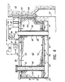
- FIG. 3 shows in section and on a larger scale one of the compartments 50 of the slab 26 identified by the reference A in FIG. 2. This same compartment is represented in vertical section in FIG. 4.
- the metal structure is composed, in addition to the external peripheral shell 52, of the internal shell 54, and of the bushing ferrules 56 ′, of a wall or upper sole 58 and of a wall or sole lower 60, the radial partitions 48 cutting, as we have seen, the interior of this metallic structure into a number of compartments 50.
- the filling concrete 62 is placed inside this structure so as to define with the latter a cooling circuit in each of the compartments 50.
- the filling concrete 62 is confined in the metal casings 64 and 65 welded to the partitions 48 and supported by tie rods 66 placed between the upper sole 58 and the upper wall of the casing 64.
- the cooling circuit formed in each of the compartments 50 is defined by a succession of spaces formed between some of the walls or ferrules of the metallic structure of the slab and the corresponding walls of the envelope 64.
- a first space 68 is defined between the outer shell 52 of the slab and the corresponding wall of the envelope 64.
- the spaces or passages 67, 68, 78 and 80, relative to each compartment 50 and defined between the ferrules 52, 54 of the slab, the ferrules of crossings 56 of the components and the envelopes 64 and 65, are cut into sectors (68a, 68b, ...) by spacers 51 which allow to have a constant spacing between the ferrules and the envelopes and to favor a uniform distribution of the cooling gas in the passages 67, 68, 78, 80.
- the gas, arriving through the orifice 86 enters the passage 68 which communicates through its lower part with a distribution box 70 defined between the lower face of the casing 64 and a wall 72 disposed opposite the lower flange 60 of the slab.
- the wall 72 is pierced with a large number of relatively close openings or holes 74 through which the cooling gas admitted into the box 70 escapes in the form of discrete jets.
- the gas then enters a supply manifold 76 defined between the partition 72 and the bottom flange 60, so as to come and lick the latter in direct contact to ensure its cooling.
- the cooling gas then rises to the upper part of the slab simultaneously by sectored spaces such as 78a, 78b, ... defined between the internal shell 54 of the slab and the corresponding wall of the casing 64, and by spaces segmented 80a, 80b, ... defined between the bushing 56 ensuring the passage of a component and the corresponding wall of the casing 65.
- Each of the spaces sectorized 78 and 80 communicates with an evacuation manifold 82 defined between the upper sole 58 of the slab and the corresponding partition of the casing 64, so that this space 82 serves as a collector for the cooling gas and allows the heating of the upper sole 58 to homogenize the temperature of the structures.
- a vertical partition 84 makes it possible to seal the "cold" cooling gas admitted through the inlet port 86 into the space 68 from the "hot” cooling gas discharged from the manifold 82 through the outlet port 88.
- the orifices 86 and 88 have been shown by way of example, for a slab hung from civil engineering 22, as being located on the upper flange 58 of the slab, but it will be understood that they can possibly be placed on the outer shell 52 for different solutions for supporting the slab.
- a chimney 89 can put the collector 76 in communication with the top of the slab, this chimney being normally closed by a plug 91 filled with concrete.
- a chimney makes it possible in particular to carry out, if necessary, in-service inspections of the lower flange 60. and of the base of the crossing ferrules 56 of the slab.
- FIGS. 5 and 6 two non-limiting examples have been shown of two alternative embodiments of the cooling circuit of the compartment designated by the reference A in FIG. 2.
- the inlet orifice 86 ' is extended by at least one vertical well 90' which opens directly into the distribution box 70 '.
- the gas used to cool the bottom flange 60 ' is brought from the collector 76' to the collector 82 'simultaneously by each of the spaces 78', 80 'and 68'. Due to the direct arrival of the cooling gas in the box 70 'through the well 90' and the return of this gas to the outlet orifice 88 'through the spaces 68', 78 'and 80', the partition 84 of the variant of Figure 4 no longer has any reason for being and can be deleted.
- This variant is essentially distinguished from the variant of FIG. 4 by the fact that the wells 90 ′ can act as chimneys (natural convection) in the event of a failure of the means normally controlling the circulation of the gas (fans 97 in FIG. 4) .
- the arrival of the gas in the box 70 "takes place as in the variant of FIG. 5 by at least one well 90" which communicates directly with the inlet orifice 86 ".
- the outlet orifice 88 is connected by at least one well 92 "to the lower part of the space 68", of such that the gas used to cool the bottom flange 60 "rises through the spaces 78" and 80 "to the manifold 82", then descends through the space 68 "before rising through the well 92" to the outlet port 88 ".
- the use of wells 90 "and 92" further improves natural convection and, therefore, operation in the event of a failure of the means for circulating the gas. cooling, compared to the variant of Figure 5.
- FIGS. 5 and 6 can be adapted correctly to the cooling of the rotary plugs, in the reactor handling phase, by an open circuit on the reactor hall, the air being conveyed by fans mounted in said plugs and discharged into the hall via a mixer, the heat flows to be removed being much lower than at nominal operation.
- the cooling gas is rapidly conveyed to the lower sole of the slab so that the cooling thereof is given priority.
- This cooling which takes place by means of discrete jets formed from the openings 74 defined in the lower partition 72 of the distribution box 70, precedes the simultaneous rise of the cooling gas along the ferrules 56 ensuring the passage of the components and the along the internal shroud 54 ensuring the passage of the large rotating plug.
- the outer shroud 52 is firstly cooled.
- a cooling circuit of this type can be defined in each of the compartments 50 defined by the partitions 48 inside the slab and in each of the compartments 50 'and 50 "defined by the partitions 48' and 48" to inside the large rotating plug 30 and the small rotating plug 34.
- the circulation of the cooling gas in each of these circuits can be achieved in different ways.
- this circulation can take place in an open circuit, the cooling gas being. then atmospheric air.
- This cooling air can either be taken outside the reactor building (not shown) overhanging the upper closings of the main tank, or directly inside this building.
- means such as fans allow air to be conveyed to the inlet orifices 86 of each of the circuits.
- cooling circuit defined in compartment A shown is placed in a closed circuit 94 which further comprises, between the outlet orifice 88 and the inlet orifice 86, an exchanger 96 ensuring the cooling of the gas by means of a cooling circuit 98, a fan 97 and, optionally, a buffer tank 99 in the case where a neutral gas is used.
- a closed circuit 94 which further comprises, between the outlet orifice 88 and the inlet orifice 86, an exchanger 96 ensuring the cooling of the gas by means of a cooling circuit 98, a fan 97 and, optionally, a buffer tank 99 in the case where a neutral gas is used.
- a circuit can group together in parallel several and even all of the cooling circuits defined in the slab and in the rotary plugs.
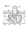
- FIG. 7 a variant of the means for cooling the lower flange 60a of the slab is shown, in which the formation of discrete jets by means of openings formed in the lower partition of a distribution box is replaced by the formation of gas vortices by means of cyclones 104, relatively few in number, distributed regularly inside the manifold 76a defined between the soleplate 60a and the corresponding wall of the envelope ' 64a. More specifically, the gas supply to each of the cyclones 104 is effected by vertical wells 90a which pass through the filling concrete 62a in order to each lead into a cyclone 104. Each cyclone 104 consists of a cylindrical housing 106 whose the vertical axis coincides with that of the corresponding well 90a.
- Each of the wells 90a opens into a cyclone 104 and the latter has a certain number of fins 108 which are arranged substantially radially inside the housing 106.
- the fins 108 have a curved shape giving the cooling gas arriving at their center by the well 90 has a vortex movement.
- Openings 109, of circular shape in the variant shown, are formed in the peripheral partition of the housing 106 to allow the cooling gas to enter the manifold 76a and to come to lick in direct contact the bottom sole 60a in order to ensure its cooling.
- the gas comes into direct contact with each of the walls to be cooled, that is to say mainly with the soleplate lower 60, the ferrules 56-, 54 and 52 and the upper sole 58.
- the temperature thus obtained being chosen according to the invention greater than 100 ° C., no sodium gel on the underside of the sole 60 or on the internal faces ferrules 56 and 54-does occur. It is thus possible to eliminate any thermal insulation at this level, which leads to an appreciable economic gain if one takes into account the cost of the metallic insulation which must be used in the nuclear reactors of the prior art whose slab is cooled to a temperature close to 50 ° C.
- the temperatures reached thanks to the cooling circuits that come. to be described depend both on the nature of the gas used, on the temperature at which this gas is injected into the cooling circuits and on the average flow rate of this gas.
- the air will enter the cooling circuits at a temperature of approximately 85 ° C to exit at a temperature of approximately 115 ° C, the average flow being 30 m 3 / s.
- maintaining the upper closings of the main tank at a temperature higher than the temperature for which the freezing of sodium deposits may occur on the surfaces bathed by the atmosphere of gas charged with steam and sodium aerosol of the slab and the rotary plugs allows to integrate into the metal structure of each of these elements some of the support flanges of the rotary plugs and other components such as pumps leading to a reduction in the weight of material used as well as the axial size. Indeed, it is known that these support flanges must be brought to a temperature preventing any gel of sodium deposition, which prohibited their integration into the structure of the slab when it was cooled to a temperature of about 50 ° C. according to the prior art, due to the thermal stresses which would have resulted therefrom.
- the support flange 95 of the large rotating plug 30 forms an integral part of both the upper sole 58 of the slab and the internal ferrule 54 of the latter.
- All the means 93 ensuring the support, the guiding and the rotation of the rotary plug 30 relative to the slab 26, as well as the sealing means 100 which are associated with them are also identical to the means known from the prior art and will not be described here in detail.
Landscapes
- Engineering & Computer Science (AREA)
- Physics & Mathematics (AREA)
- Plasma & Fusion (AREA)
- General Engineering & Computer Science (AREA)
- High Energy & Nuclear Physics (AREA)
- Health & Medical Sciences (AREA)
- Life Sciences & Earth Sciences (AREA)
- Biomedical Technology (AREA)
- General Health & Medical Sciences (AREA)
- Molecular Biology (AREA)
- Structure Of Emergency Protection For Nuclear Reactors (AREA)
- Monitoring And Testing Of Nuclear Reactors (AREA)
Applications Claiming Priority (2)
| Application Number | Priority Date | Filing Date | Title |
|---|---|---|---|
| FR8026082A FR2495815B1 (fr) | 1980-12-09 | 1980-12-09 | Reacteur nucleaire refroidi par un metal liquide contenu dans une cuve obturee par des fermetures superieures |
| FR8026082 | 1980-12-09 |
Publications (2)
| Publication Number | Publication Date |
|---|---|
| EP0055643A1 true EP0055643A1 (de) | 1982-07-07 |
| EP0055643B1 EP0055643B1 (de) | 1984-07-25 |
Family
ID=9248830
Family Applications (1)
| Application Number | Title | Priority Date | Filing Date |
|---|---|---|---|
| EP81401896A Expired EP0055643B1 (de) | 1980-12-09 | 1981-11-30 | Kernreaktor, der von einem flüssigen Metall gekühlt wird, das in einem oben angeordnete Verschlüsse aufweisenden Behälter enthalten ist |
Country Status (5)
| Country | Link |
|---|---|
| US (1) | US4464334A (de) |
| EP (1) | EP0055643B1 (de) |
| JP (1) | JPS57120887A (de) |
| DE (1) | DE3165123D1 (de) |
| FR (1) | FR2495815B1 (de) |
Cited By (9)
| Publication number | Priority date | Publication date | Assignee | Title |
|---|---|---|---|---|
| EP0095428A1 (de) * | 1982-05-26 | 1983-11-30 | Novatome | Gaskühleinrichtung für den Druckbehälterdeckel eines Kernreaktors |
| US4464334A (en) * | 1980-12-09 | 1984-08-07 | Commissariat A L'energie Atomique | Fast neutron nuclear reactors |
| FR2554489A1 (fr) * | 1983-11-09 | 1985-05-10 | Nira Spa | Dalle en beton arme pour reacteur nucleaire, notamment du type rapide |
| FR2556874A1 (fr) * | 1983-12-20 | 1985-06-21 | Nira Spa | Bouchon pour coeur de reacteur nucleaire rapide, integre dans le petit couvercle tournant du reacteur. |
| EP0153054A1 (de) * | 1984-02-23 | 1985-08-28 | National Nuclear Corporation Limited | Kernreaktoren oder Teile davon |
| FR2560707A1 (fr) * | 1984-03-02 | 1985-09-06 | Commissariat Energie Atomique | Reacteur nucleaire a neutrons rapides comprenant une cuve principale et une dalle de fermeture suspendues |
| FR2562709A1 (fr) * | 1984-04-06 | 1985-10-11 | Nat Nuclear Corp Ltd | Reacteur nucleaire a blindages rotatifs |
| EP0166950A1 (de) * | 1984-06-07 | 1986-01-08 | INTERATOM Gesellschaft mit beschränkter Haftung | Im Naturumlauf betreibbare Kernreaktor-Deckelkühlung |
| FR2671224A1 (fr) * | 1990-12-26 | 1992-07-03 | Commissariat Energie Atomique | Dalle de fermeture de la cuve metallique d'un reacteur nucleaire a neutrons rapides. |
Families Citing this family (4)
| Publication number | Priority date | Publication date | Assignee | Title |
|---|---|---|---|---|
| US4655998A (en) * | 1982-12-03 | 1987-04-07 | National Nuclear Corporation Limited | Liquid metal cooled nuclear rector constructions |
| FR2554270B1 (fr) * | 1983-10-28 | 1986-02-07 | Novatome | Dispositif de protection thermique d'un composant d'un reacteur nucleaire a neutrons rapides |
| US4678626A (en) * | 1985-12-02 | 1987-07-07 | General Electric Company | Radiant vessel auxiliary cooling system |
| JP3597165B2 (ja) * | 2001-11-16 | 2004-12-02 | 核燃料サイクル開発機構 | 原子炉容器の熱荷重緩和装置 |
Citations (7)
| Publication number | Priority date | Publication date | Assignee | Title |
|---|---|---|---|---|
| US3016462A (en) * | 1958-04-28 | 1962-01-09 | Smith Corp A O | Multi-layer vessel having a gamma ray flux absorbing layer |
| US3493758A (en) * | 1965-05-11 | 1970-02-03 | Atomic Energy Authority Uk | Radiation shielding and cooling for nuclear reactor utilizing molten metal |
| DE2113672A1 (de) * | 1971-03-20 | 1972-09-21 | Kraftwerk Union Ag | Betondruckbehaelter fuer Druck- oder Siedewasser-Kernreaktoren |
| GB1412764A (en) * | 1972-09-28 | 1975-11-05 | Nuclear Power Co Whetstone Ltd | Nuclear reactors |
| US4116705A (en) * | 1973-06-01 | 1978-09-26 | Stablex Ag | Detoxification |
| US4124447A (en) * | 1974-12-06 | 1978-11-07 | Siempelkamp Giesserei Kg | Pressure vessel for nuclear reactor |
| DE2732741A1 (de) * | 1977-07-20 | 1979-02-01 | Ght Hochtemperaturreak Tech | Reflektordecke fuer hochtemperaturreaktor |
Family Cites Families (9)
| Publication number | Priority date | Publication date | Assignee | Title |
|---|---|---|---|---|
| FR2138327B1 (de) * | 1971-05-24 | 1974-03-08 | Commissariat Energie Atomique | |
| FR2235460B1 (de) * | 1973-06-26 | 1978-03-24 | Commissariat Energie Atomique | |
| DE2538583A1 (de) * | 1974-08-30 | 1976-03-11 | Commissariat Energie Atomique | Kuehlvorrichtung fuer das obere ende eines aufgehaengten behaelters, besonders eines kernreaktorbehaelters |
| US4116765A (en) * | 1976-04-27 | 1978-09-26 | Commissariat A L'energie Atomique | Liquid metal cooled nuclear reactor |
| DE2709914C2 (de) * | 1977-03-08 | 1986-10-09 | INTERATOM GmbH, 5060 Bergisch Gladbach | Flüssigmetallgekühlter Kernreaktor mit Einrichtungen zur Verhinderung der Konvektion von Metalldämpfen |
| FR2419565A1 (fr) * | 1978-03-07 | 1979-10-05 | Commissariat Energie Atomique | Echangeur d'ultime secours, notamment pour reacteur nucleaire a neutrons rapides |
| JPS54145897A (en) * | 1978-05-09 | 1979-11-14 | Toshiba Corp | Dipped plate for fast breeder |
| FR2460527A1 (fr) * | 1979-06-29 | 1981-01-23 | Commissariat Energie Atomique | Dispositif d'homogeneisation dans le sens circonferentiel des temperatures de la virole d'un composant traversant la dalle superieure d'un reacteur nucleaire |
| FR2495815B1 (fr) * | 1980-12-09 | 1986-09-19 | Commissariat Energie Atomique | Reacteur nucleaire refroidi par un metal liquide contenu dans une cuve obturee par des fermetures superieures |
-
1980
- 1980-12-09 FR FR8026082A patent/FR2495815B1/fr not_active Expired
-
1981
- 1981-11-30 US US06/325,762 patent/US4464334A/en not_active Expired - Fee Related
- 1981-11-30 EP EP81401896A patent/EP0055643B1/de not_active Expired
- 1981-11-30 DE DE8181401896T patent/DE3165123D1/de not_active Expired
- 1981-12-04 JP JP56195518A patent/JPS57120887A/ja active Granted
Patent Citations (7)
| Publication number | Priority date | Publication date | Assignee | Title |
|---|---|---|---|---|
| US3016462A (en) * | 1958-04-28 | 1962-01-09 | Smith Corp A O | Multi-layer vessel having a gamma ray flux absorbing layer |
| US3493758A (en) * | 1965-05-11 | 1970-02-03 | Atomic Energy Authority Uk | Radiation shielding and cooling for nuclear reactor utilizing molten metal |
| DE2113672A1 (de) * | 1971-03-20 | 1972-09-21 | Kraftwerk Union Ag | Betondruckbehaelter fuer Druck- oder Siedewasser-Kernreaktoren |
| GB1412764A (en) * | 1972-09-28 | 1975-11-05 | Nuclear Power Co Whetstone Ltd | Nuclear reactors |
| US4116705A (en) * | 1973-06-01 | 1978-09-26 | Stablex Ag | Detoxification |
| US4124447A (en) * | 1974-12-06 | 1978-11-07 | Siempelkamp Giesserei Kg | Pressure vessel for nuclear reactor |
| DE2732741A1 (de) * | 1977-07-20 | 1979-02-01 | Ght Hochtemperaturreak Tech | Reflektordecke fuer hochtemperaturreaktor |
Non-Patent Citations (1)
| Title |
|---|
| Rapport ANL-5719, Mai 1957, No. 148 LJ. KOCH et al. " Experimental Breeder Reactor II (EBR-II)" page 148 *figure 34* * |
Cited By (12)
| Publication number | Priority date | Publication date | Assignee | Title |
|---|---|---|---|---|
| US4464334A (en) * | 1980-12-09 | 1984-08-07 | Commissariat A L'energie Atomique | Fast neutron nuclear reactors |
| EP0095428A1 (de) * | 1982-05-26 | 1983-11-30 | Novatome | Gaskühleinrichtung für den Druckbehälterdeckel eines Kernreaktors |
| FR2527827A1 (fr) * | 1982-05-26 | 1983-12-02 | Novatome | Dispositif de refroidissement par gaz de la dalle de fermeture de la cuve d'un reacteur nucleaire |
| FR2554489A1 (fr) * | 1983-11-09 | 1985-05-10 | Nira Spa | Dalle en beton arme pour reacteur nucleaire, notamment du type rapide |
| FR2556874A1 (fr) * | 1983-12-20 | 1985-06-21 | Nira Spa | Bouchon pour coeur de reacteur nucleaire rapide, integre dans le petit couvercle tournant du reacteur. |
| DE3432639A1 (de) * | 1983-12-20 | 1985-06-27 | Nira S.p.A., Genua | Im kleinen drehverschluss eines schnellen kernreaktors integrierter verschluss des reaktorkerns |
| EP0153054A1 (de) * | 1984-02-23 | 1985-08-28 | National Nuclear Corporation Limited | Kernreaktoren oder Teile davon |
| FR2560707A1 (fr) * | 1984-03-02 | 1985-09-06 | Commissariat Energie Atomique | Reacteur nucleaire a neutrons rapides comprenant une cuve principale et une dalle de fermeture suspendues |
| EP0156689A1 (de) * | 1984-03-02 | 1985-10-02 | Commissariat A L'energie Atomique | Schneller Kernreaktor mit hängendem Hauptbecken und Deckel |
| FR2562709A1 (fr) * | 1984-04-06 | 1985-10-11 | Nat Nuclear Corp Ltd | Reacteur nucleaire a blindages rotatifs |
| EP0166950A1 (de) * | 1984-06-07 | 1986-01-08 | INTERATOM Gesellschaft mit beschränkter Haftung | Im Naturumlauf betreibbare Kernreaktor-Deckelkühlung |
| FR2671224A1 (fr) * | 1990-12-26 | 1992-07-03 | Commissariat Energie Atomique | Dalle de fermeture de la cuve metallique d'un reacteur nucleaire a neutrons rapides. |
Also Published As
| Publication number | Publication date |
|---|---|
| JPS6363080B2 (de) | 1988-12-06 |
| DE3165123D1 (en) | 1984-08-30 |
| FR2495815B1 (fr) | 1986-09-19 |
| JPS57120887A (en) | 1982-07-28 |
| FR2495815A1 (fr) | 1982-06-11 |
| EP0055643B1 (de) | 1984-07-25 |
| US4464334A (en) | 1984-08-07 |
Similar Documents
| Publication | Publication Date | Title |
|---|---|---|
| EP0055643B1 (de) | Kernreaktor, der von einem flüssigen Metall gekühlt wird, das in einem oben angeordnete Verschlüsse aufweisenden Behälter enthalten ist | |
| EP0022714B1 (de) | Mit einem Flüssigmetall gekühlter schnelle Neutronen-Kernreaktor mit einem System zum Abführen der Restwärme | |
| FR2718880A1 (fr) | Réacteur nucléaire refroidi par un métal liquide. | |
| FR2763168A1 (fr) | Reacteur nucleaire a eau, dont la cuve contient un dispositif de recuperation du coeur apres sa fusion accidentelle | |
| FR2620559A1 (fr) | Reacteur nucleaire a metal liquide supporte par le fond | |
| EP0324807B1 (de) | Vorrichtung zur verhinderung des eindringens einer kernreaktorcorschmelze in das erdreich | |
| EP0055963B1 (de) | Flüssigmetallgekühlter Kernreaktor mit einem am Boden gekühlten Behälter | |
| EP0163564B1 (de) | Schneller Neutronenkernreaktor mit Dampferzeuger, integriert im Behälter | |
| EP0153225B1 (de) | Wärmetauscher mit einem Notkühlsystem und schneller Kernreaktor mit einem derartigen Wärmetauscher | |
| EP0105781B1 (de) | Sekundärer Kühlkreislauf für einen Flüssigmetall-gekühlten Kernreaktor und Dampferzeuger angepasst an einen solchen Kreislauf | |
| EP0083545B1 (de) | Sicherheitsvorrichtung zur Ableitung der entstehenden Wärme beim Abschalten eines schnellen Brüters | |
| EP0018262B1 (de) | Schneller Kernreaktor mit einem zylindrischen Innenbehälter | |
| EP0006800B1 (de) | Mit flüssigem Metall gekühlter schneller Kernreaktor | |
| EP0258131B1 (de) | Notkühleinrichtung für schnellen Neutronenreaktor | |
| EP0064920B1 (de) | Vorrichtung zur Dampferzeugung und zur Ableitung von Wärme in einem schnellen Brüter | |
| WO2025016985A1 (fr) | Réacteur nucléaire à assemblages combustibles solides, étanches et refroidis individuellement en fonctionnement nominal par des caloducs | |
| EP0156689B1 (de) | Schneller Kernreaktor mit hängendem Hauptbecken und Deckel | |
| EP0095428B1 (de) | Gaskühleinrichtung für den Druckbehälterdeckel eines Kernreaktors | |
| EP0104994B1 (de) | Sekundärer Kühlkreislauf für einen Flüssigmetall-gekühlten Kernreaktor | |
| EP0144256B1 (de) | Anordnung zur thermischen Abschirmung einer Komponente eines Kernreaktors mit schnellen Neutronen | |
| EP0049197A1 (de) | Wärmedämmvorrichtung zum Isolieren des oberen Bereichs eines zwischen dem Hauptbehälter und dem Sicherheitsbehälter eines Kernreaktors liegenden Ringraumes | |
| EP0161949B1 (de) | Mit flüssigem Metall gekühlter Kernreaktor | |
| EP0024990A1 (de) | Vorrichtung zum Transport bestrahlten Kernbrennstoffs durch die Abdeckplatte eines Kernreaktors hindurch | |
| EP0382643A1 (de) | Wärmeschutzvorrichtung eines oberen Tragringes eines hängenden Gefässes, insbesondere in einem schnellen Neutronenkernreaktor | |
| EP0119915A1 (de) | Integrierter Schnellbrüter |
Legal Events
| Date | Code | Title | Description |
|---|---|---|---|
| PUAI | Public reference made under article 153(3) epc to a published international application that has entered the european phase |
Free format text: ORIGINAL CODE: 0009012 |
|
| AK | Designated contracting states |
Designated state(s): BE DE GB IT NL |
|
| 17P | Request for examination filed |
Effective date: 19821202 |
|
| ITF | It: translation for a ep patent filed | ||
| GRAA | (expected) grant |
Free format text: ORIGINAL CODE: 0009210 |
|
| AK | Designated contracting states |
Designated state(s): BE DE GB IT NL |
|
| REF | Corresponds to: |
Ref document number: 3165123 Country of ref document: DE Date of ref document: 19840830 |
|
| PLBE | No opposition filed within time limit |
Free format text: ORIGINAL CODE: 0009261 |
|
| STAA | Information on the status of an ep patent application or granted ep patent |
Free format text: STATUS: NO OPPOSITION FILED WITHIN TIME LIMIT |
|
| 26N | No opposition filed | ||
| PGFP | Annual fee paid to national office [announced via postgrant information from national office to epo] |
Ref country code: NL Payment date: 19871130 Year of fee payment: 7 |
|
| PG25 | Lapsed in a contracting state [announced via postgrant information from national office to epo] |
Ref country code: NL Effective date: 19890601 |
|
| NLV4 | Nl: lapsed or anulled due to non-payment of the annual fee | ||
| PGFP | Annual fee paid to national office [announced via postgrant information from national office to epo] |
Ref country code: BE Payment date: 19891024 Year of fee payment: 9 |
|
| PG25 | Lapsed in a contracting state [announced via postgrant information from national office to epo] |
Ref country code: BE Effective date: 19901130 |
|
| BERE | Be: lapsed |
Owner name: COMMISSARIAT A L'ENERGIE ATOMIQUE ETABLISSEMENT D Effective date: 19901130 |
|
| PGFP | Annual fee paid to national office [announced via postgrant information from national office to epo] |
Ref country code: DE Payment date: 19911029 Year of fee payment: 11 |
|
| PGFP | Annual fee paid to national office [announced via postgrant information from national office to epo] |
Ref country code: GB Payment date: 19911126 Year of fee payment: 11 |
|
| PG25 | Lapsed in a contracting state [announced via postgrant information from national office to epo] |
Ref country code: GB Effective date: 19921130 |
|
| GBPC | Gb: european patent ceased through non-payment of renewal fee |
Effective date: 19921130 |
|
| PG25 | Lapsed in a contracting state [announced via postgrant information from national office to epo] |
Ref country code: DE Effective date: 19930803 |