EP0055793A2 - Dispositif pour le délignage de planches - Google Patents
Dispositif pour le délignage de planches Download PDFInfo
- Publication number
- EP0055793A2 EP0055793A2 EP81106664A EP81106664A EP0055793A2 EP 0055793 A2 EP0055793 A2 EP 0055793A2 EP 81106664 A EP81106664 A EP 81106664A EP 81106664 A EP81106664 A EP 81106664A EP 0055793 A2 EP0055793 A2 EP 0055793A2
- Authority
- EP
- European Patent Office
- Prior art keywords
- pair
- cutting plane
- boards
- board
- positioning points
- Prior art date
- Legal status (The legal status is an assumption and is not a legal conclusion. Google has not performed a legal analysis and makes no representation as to the accuracy of the status listed.)
- Granted
Links
Images

Classifications
-
- B—PERFORMING OPERATIONS; TRANSPORTING
- B27—WORKING OR PRESERVING WOOD OR SIMILAR MATERIAL; NAILING OR STAPLING MACHINES IN GENERAL
- B27B—SAWS FOR WOOD OR SIMILAR MATERIAL; COMPONENTS OR ACCESSORIES THEREFOR
- B27B5/00—Sawing machines working with circular or cylindrical saw blades; Components or equipment therefor
- B27B5/02—Sawing machines working with circular or cylindrical saw blades; Components or equipment therefor characterised by a special purpose only
- B27B5/04—Sawing machines working with circular or cylindrical saw blades; Components or equipment therefor characterised by a special purpose only for edge trimming
-
- B—PERFORMING OPERATIONS; TRANSPORTING
- B27—WORKING OR PRESERVING WOOD OR SIMILAR MATERIAL; NAILING OR STAPLING MACHINES IN GENERAL
- B27B—SAWS FOR WOOD OR SIMILAR MATERIAL; COMPONENTS OR ACCESSORIES THEREFOR
- B27B31/00—Arrangements for conveying, loading, turning, adjusting, or discharging the log or timber, specially designed for saw mills or sawing machines
- B27B31/06—Adjusting equipment, e.g. using optical projection
-
- Y—GENERAL TAGGING OF NEW TECHNOLOGICAL DEVELOPMENTS; GENERAL TAGGING OF CROSS-SECTIONAL TECHNOLOGIES SPANNING OVER SEVERAL SECTIONS OF THE IPC; TECHNICAL SUBJECTS COVERED BY FORMER USPC CROSS-REFERENCE ART COLLECTIONS [XRACs] AND DIGESTS
- Y10—TECHNICAL SUBJECTS COVERED BY FORMER USPC
- Y10T—TECHNICAL SUBJECTS COVERED BY FORMER US CLASSIFICATION
- Y10T83/00—Cutting
- Y10T83/444—Tool engages work during dwell of intermittent workfeed
- Y10T83/463—Work-feed element contacts and moves with work
- Y10T83/4635—Comprises element entering aperture in, or engaging abutment surface on, work
-
- Y—GENERAL TAGGING OF NEW TECHNOLOGICAL DEVELOPMENTS; GENERAL TAGGING OF CROSS-SECTIONAL TECHNOLOGIES SPANNING OVER SEVERAL SECTIONS OF THE IPC; TECHNICAL SUBJECTS COVERED BY FORMER USPC CROSS-REFERENCE ART COLLECTIONS [XRACs] AND DIGESTS
- Y10—TECHNICAL SUBJECTS COVERED BY FORMER USPC
- Y10T—TECHNICAL SUBJECTS COVERED BY FORMER US CLASSIFICATION
- Y10T83/00—Cutting
- Y10T83/768—Rotatable disc tool pair or tool and carrier
- Y10T83/7684—With means to support work relative to tool[s]
- Y10T83/7693—Tool moved relative to work-support during cutting
Definitions
- the invention relates to a method and a device for trimming wooden boards.
- Untrimmed boards generally have a conical shape, since the tree trunk from which they were sawn is also conical. If the boards are to be used in a joint gluing system to be glued to wooden panels of greater width, it is necessary to trimm them. This can be done, for example, by passing the boards through two saws arranged parallel to one another. This creates a lot of waste, since the overall board width is determined by the narrowest point. Attempts have also been made to taper the boards to reduce waste. The previously known methods and devices have not worked satisfactorily in terms of cut quality and capacity. Especially when cutting hardwood it is; required to hold the board in place while sawing, i.e. the saw makes the relative movement while the board is stationary.
- the boards are again not exactly rectangular in cross-section, but one surface of the board is wider than the other. If a straight edge is cut during trimming, the larger surface is practically reduced to the size of the smaller surface. This creates additional waste.
- the invention is based on the object of creating a method and a device of the type mentioned at the outset, and at the same time allowing a high capacity with good cut quality and little waste.
- This task is basically through the procedural steps of claim 1 and the device features of claim 2 solved.
- the untrimmed boards are first positioned using a special device, i.e. Two positioning points are defined for each edge, the straight connecting line of which results in a clean cutting edge.
- the board prepared in this way is transported into the first cutting plane with the aid of the stop pair and the slide, the stop pair being correspondingly assigned to the cutting plane, i.e.
- the pair of stops always performs a certain stroke perpendicular to the cutting plane and ensures that the assigned positioning points reach the cutting plane.
- the ejector pair pushes the board from the area of the first cutting plane with the rear edge into the second cutting plane.
- the front edge of one board is always cut at the same time as the rear edge of the previous board.
- the invention can also be used for reworking timber that has already been trimmed once, in particular hardwood. Due to the temporary storage of the trimmed wood, warping may occur. As a result, the cut edge is deformed so that perfect gluing is no longer possible. In this case, a new trimming may be carried out using a special cutting tool. The use of the device for positioning can be omitted.
- the cutting plane is determined by the cutting tool or tools, which can be different tools.
- each cutting plane can be formed by a separate tool, a saw or a milling cutter.
- two milling cutters rotating around a vertical axis can be provided, the milling profiles of which are stepped and arranged in such a way that the section with the largest diameter of one milling cutter is assigned to the section with the smallest diameter of the other milling cutter, the two milling cutters being arranged offset with respect to one another in the feed direction could be.
- the boards can be fed in such a way that the larger surfaces of the boards are in the area of the smallest diameter of the milling cutter, so that there is only so little of the bevelled edges due to the natural growth as is absolutely necessary.
- the profiles do not * fit together immediately, but a * less material is removed during milling. If gluing in a joint gluing system is required, every other board must be turned over.
- the device according to the invention is composed of two main devices.
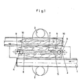
- the positioning points are defined in the first device (FIG. 1). Trimming takes place in the second facility.
- the device shown in Fig. 1 consists of a roller conveyor 1 for feeding the boards to be trimmed 5 on a work table.
- the stands for the operators are marked with 2.
- Milling cutters 3 and 4 are assigned to these two directives 7 and 8.
- a milling cutter, for example milling cutter 3 is adjustable, as indicated by the arrow, in order to enable adaptation to boards of different lengths.
- Two boards 5 are arranged so that the desired cutting lines coincide with the shadow 7 and 8 respectively.
- the milling cutters are then actuated and generate positioning points 9-9 and 10-10. These positioning points define two cutting lines for clean cuts.
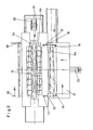
- the actual trimming device begins with a roller conveyor 14 which conveys the boards with the positioning points 9-9 ' and 10-10 into the work area.
- a roller conveyor 14 which conveys the boards with the positioning points 9-9 ' and 10-10 into the work area.
- the stop pair 15 On the slide 21, which can be moved back and forth essentially perpendicularly to the longitudinal extent of the boards to be trimmed with the aid of a drive 22 and a guide 23, the stop pair 15 carries the slide 16 and the ejector pair: 17.
- the slider 16 which in this embodiment also forms a pair of slides, can be moved back and forth in addition to the slide by a drive 20 which is arranged on the slide 21.
- the pair of stops 15 and the pair of ejectors 17 are pivotally mounted on the carriage, specifically as indicated by arrows.
- the pivoting movement is carried out by a pneumatic cylinder 18 and a corresponding kinematics 19.
- the saws 24 and 25 are circular saws which are mounted at 26, connected to a drive at 28 and movable up and down at 27. With 29 a suction device is designated.
- Saw 24 is associated with a jig 11 and saw 25 is associated with a jig 12.
- a braking device that prevents undesired rushing of the boards, is denoted by 13.
- the trimmed boards are led out of the device at 30.
- the waste falls into a container 31 or conveyor belt.
- the waste is shorter than the remaining board due to the processing of the first device and therefore falls between the support 30.
- the boards provided with the positioning points 9-9 and 10-10 are conveyed through the roller conveyor 14 into the area of the machine.
- a board lying in this area is designated 5a.
- the slider 16 pushes the board 5a with the positioning points against the corresponding stops of the stopper pair 15.
- the slider 16 is preferably also designed as a pair (see FIG. 2) so that it engages in the neatly prepared positioning points. Basically, it is sufficient if the slide ensures that the board is pushed against the stops of the stopper pair 15.
- the two positioning points 10-10 are already parallel to the cutting plane of the saw 24. Together with the slide, the board 5a is then advanced so far by the drive 22 that it assumes the position 5b. A board lying in position 5b under the tensioning device 11 and already trimmed on its front edge is advanced by the ejector pair 17 into position 5c. The ejectors of the ejector pair 17 come to rest at the positioning points 9, which correspond to the cutting plane of the saw 25.
- Stop pair 15 and ejector pair 17 perform the stroke indicated by the arrow.
- the stops of the stop pair 15 lie parallel to the cutting plane of the saw 24 and the ejectors of the ejector pair 17 lie parallel to the cutting plane of the saw 25.
- the distance between the stop pair and the ejector pair is constant and corresponds to the distance between the cutting planes of the two saws 24 and 25 .
- the device according to the invention allows two edges to be trimmed at the same time, the boards being firmly clamped and unable to move.
- the saws perform the relative movement and also ensure a clean cut at Hartholt.
- the parts of the device (pair of stops and ejector pair) which move the boards into the area of the cutting planes can be moved back immediately after they have carried out this movement and the boards are clamped. You are then ready to start a new one Advance board when the cut is finished.
- the stop pair and ejector pair do not hinder the sawing. Trimming can be carried out completely automatically with a high output per unit of time.
- a stop 15, a slide part 16 and an ejector 17 on one side are adjustable transversely to the working direction, as indicated by an arrow, in order to enable adaptation to boards of different lengths.
- the support 30 is correspondingly adjustable for removal.
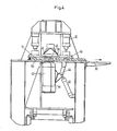
- the embodiment according to FIG. 4 differs only from that according to FIGS. 1 to 3 in that cutters are provided instead of the two saws.
- cutters are provided instead of the two saws.
- the device according to FIG. 4 basically works like that according to FIGS. 1 to 3. Since the two cutters 41 and 43 are arranged in such a way that the largest diameter section of one cutter 41 is assigned to the smallest diameter section of the cutter 43 the front edge of the board in position 5b is provided with a stepped profile corresponding to the shape of the milling cutter 41.
- the cutter 43 creates a "reverse" profile on the rear edge which fits the first profile and can be pushed together with it.
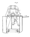
- a milling cutter 48 which rotates around a vertical axis and also has a stepped profile.
- the boards are preferably inserted in such a way that their larger surfaces - due to the bevel on the sides due to the natural growth - are assigned to the section of the smallest diameter of the milling cutter 48. 5, the larger surface is at the bottom.
- the milling cutter then creates a beveled profile on the front and rear edge, which corresponds to the shape due to the natural curve of the tree and thus cuts off as little material as possible.
- the profiles of the trimmed boards then do not fit into each other (see Fig. 5), but it is possible to turn every other board over and thus enable gluing.
- the device according to FIG. 5 or the device according to FIG. 4 is used depends on the requirements which are preferred. If the device according to FIG. 4 is used, a little more material has to be removed, but joint gluing is possible without further handling. If the device according to FIG. 5 is used, the waste is less, but gluing in a joint gluing system is only possible by turning every other board.
- the invention is directed to the trimming of raw boards.
- boards that have already been trimmed are warped by interim storage so that they can no longer be glued directly.
- a slight trimming is necessary again.
- positioning by a device according to FIG. 1 is not necessary, since only a small amount may have to be machined by a special tool.
Landscapes
- Life Sciences & Earth Sciences (AREA)
- Engineering & Computer Science (AREA)
- Mechanical Engineering (AREA)
- Wood Science & Technology (AREA)
- Forests & Forestry (AREA)
- Sawing (AREA)
- Control And Other Processes For Unpacking Of Materials (AREA)
- Dovetailed Work, And Nailing Machines And Stapling Machines For Wood (AREA)
- Massaging Devices (AREA)
- Orthopedics, Nursing, And Contraception (AREA)
- Baking, Grill, Roasting (AREA)
Priority Applications (1)
| Application Number | Priority Date | Filing Date | Title |
|---|---|---|---|
| AT81106664T ATE12607T1 (de) | 1980-12-27 | 1981-08-27 | Vorrichtung zum besaeumen von holzbrettern. |
Applications Claiming Priority (2)
| Application Number | Priority Date | Filing Date | Title |
|---|---|---|---|
| DE19803049258 DE3049258A1 (de) | 1980-12-27 | 1980-12-27 | Verfahren und vorrichtung zum besaeumen von holzbrettern |
| DE3049258 | 1980-12-27 |
Publications (3)
| Publication Number | Publication Date |
|---|---|
| EP0055793A2 true EP0055793A2 (fr) | 1982-07-14 |
| EP0055793A3 EP0055793A3 (en) | 1983-08-03 |
| EP0055793B1 EP0055793B1 (fr) | 1985-04-10 |
Family
ID=6120435
Family Applications (1)
| Application Number | Title | Priority Date | Filing Date |
|---|---|---|---|
| EP81106664A Expired EP0055793B1 (fr) | 1980-12-27 | 1981-08-27 | Dispositif pour le délignage de planches |
Country Status (7)
| Country | Link |
|---|---|
| US (1) | US4449558A (fr) |
| EP (1) | EP0055793B1 (fr) |
| AT (1) | ATE12607T1 (fr) |
| DE (2) | DE3049258A1 (fr) |
| FI (1) | FI812806L (fr) |
| NO (1) | NO812921L (fr) |
| SU (1) | SU1103786A3 (fr) |
Cited By (1)
| Publication number | Priority date | Publication date | Assignee | Title |
|---|---|---|---|---|
| US5179883A (en) * | 1990-07-30 | 1993-01-19 | Hans Payr | Apparatus for dividing wood |
Families Citing this family (5)
| Publication number | Priority date | Publication date | Assignee | Title |
|---|---|---|---|---|
| US4619163A (en) * | 1984-07-09 | 1986-10-28 | Brown Irving J | Automatic mitering apparatus |
| US4676130A (en) * | 1986-02-25 | 1987-06-30 | Filer & Stowell Co., Inc. | Lumber edger |
| DE4114836A1 (de) * | 1991-04-25 | 1992-10-29 | Josef Hildebrand | Verfahren und vorrichtung zum besaeumen von massivholz auf einer tischkreissaege |
| US10118785B2 (en) | 2015-02-23 | 2018-11-06 | Chs Automation | Assembly and process for a press feed mechanism for providing rapid, efficient and tuned hold and release displacement of an upper feed roller relative to a lower roller and between which is communicated a sheet material for subsequent feeding into a press operation |
| CN112248138A (zh) * | 2020-09-11 | 2021-01-22 | 邹自强 | 一种木板加工用切割成型设备 |
Family Cites Families (13)
| Publication number | Priority date | Publication date | Assignee | Title |
|---|---|---|---|---|
| US1420976A (en) * | 1920-11-02 | 1922-06-27 | Dickerson Glue Jointer Company | Lumber-joining machine |
| US1795953A (en) * | 1930-02-14 | 1931-03-10 | Arthur B Johnson | Lap-joint-forming machine |
| DE855491C (de) * | 1942-04-12 | 1952-11-13 | Daimler Benz Ag | Pleuelstange mit geteiltem Lager |
| FR1068740A (fr) * | 1952-08-01 | 1954-06-30 | Déligneuse automatique à deux lames fixes | |
| GB1031675A (en) * | 1962-01-18 | 1966-06-02 | Wadkin Ltd | Improvements in or relating to planing or facing machines |
| SE220580C1 (fr) * | 1962-10-19 | 1968-05-14 | ||
| SE313171B (fr) * | 1962-12-21 | 1969-08-04 | Stora Kopparbergs Bergslags Ab | |
| DE1628884A1 (de) * | 1967-12-29 | 1971-12-23 | Otto Kreibaum | Verfahren und Vorrichtung zur Gewinnung von auf Format geschnittenem Schnittholz aus konisch wachsenden Staemmen |
| CH472941A (fr) * | 1968-01-24 | 1969-05-31 | Meyrat & Luisoni | Procédé pour l'usinage d'un matériau en barre et installation pour la mise en oeuvre de ce procédé |
| GB1484738A (en) * | 1975-01-25 | 1977-09-01 | Storti G | Apparatus for automatically trimming lengths of wood |
| US4167961A (en) * | 1978-04-13 | 1979-09-18 | New England Log Homes, Inc. | Planer and groover |
| US4240477A (en) * | 1979-05-29 | 1980-12-23 | Saab-Scania Aktiebolag | Movable support assembly for a board infeed system |
| SU918095A1 (ru) * | 1979-09-28 | 1982-04-07 | Всесоюзный проектно-конструкторский и технологический институт мебели | Устройство дл фрезеровани кромок дерев нных деталей |
-
1980
- 1980-12-27 DE DE19803049258 patent/DE3049258A1/de not_active Withdrawn
-
1981
- 1981-08-26 US US06/296,313 patent/US4449558A/en not_active Expired - Fee Related
- 1981-08-27 EP EP81106664A patent/EP0055793B1/fr not_active Expired
- 1981-08-27 NO NO812921A patent/NO812921L/no unknown
- 1981-08-27 AT AT81106664T patent/ATE12607T1/de not_active IP Right Cessation
- 1981-08-27 DE DE8181106664T patent/DE3169837D1/de not_active Expired
- 1981-09-09 FI FI812806A patent/FI812806L/fi not_active Application Discontinuation
- 1981-10-20 SU SU813346751A patent/SU1103786A3/ru active
Cited By (1)
| Publication number | Priority date | Publication date | Assignee | Title |
|---|---|---|---|---|
| US5179883A (en) * | 1990-07-30 | 1993-01-19 | Hans Payr | Apparatus for dividing wood |
Also Published As
| Publication number | Publication date |
|---|---|
| ATE12607T1 (de) | 1985-04-15 |
| FI812806A7 (fi) | 1982-06-28 |
| DE3049258A1 (de) | 1982-07-29 |
| FI812806L (fi) | 1982-06-28 |
| EP0055793B1 (fr) | 1985-04-10 |
| NO812921L (no) | 1982-06-28 |
| US4449558A (en) | 1984-05-22 |
| DE3169837D1 (en) | 1985-05-15 |
| EP0055793A3 (en) | 1983-08-03 |
| SU1103786A3 (ru) | 1984-07-15 |
Similar Documents
| Publication | Publication Date | Title |
|---|---|---|
| AT218725B (de) | Maschine zur Herstellung von Kleinparkettbrettchen | |
| DE2010060C3 (de) | Holzbearbeitungsmaschine für Rundholz | |
| DE3020917A1 (de) | Buntaufteilanlage fuer plattenartige werkstuecke | |
| DE102009033813B4 (de) | Vorrichtung zum Aufteilen einer großformatigen Platte | |
| DE19727127C1 (de) | Verfahren und Vorrichtung zur Herstellung von schmalen Furnierstreifen | |
| EP0437245A2 (fr) | Procédé et dispositif pour la fabrication d'assemblages par dents collées | |
| DE19603933A1 (de) | Vorrichtung zur Bearbeitung von Platten | |
| EP0261568B1 (fr) | Machine à travailler le bois | |
| EP1810769A1 (fr) | Machine à usiner des panneaux avec unité de sciage | |
| EP0055793B1 (fr) | Dispositif pour le délignage de planches | |
| EP4696475A2 (fr) | Dispositif de traitement du bois, installation de traitement du bois et procédé | |
| DE2636529A1 (de) | Saegemaschine fuer oberflaechenbeschichtete platten | |
| DE3307809A1 (de) | Holzbearbeitungsmaschine | |
| EP0292864B1 (fr) | Machine pour travailler le bois | |
| DE19503433C2 (de) | Vorrichtung und Verfahren zum Zuschneiden plattenförmiger Stränge | |
| DE1503937A1 (de) | Verfahren zum Saegen von Staemmen zu Brettern,Planken und Schwellen | |
| EP0394521B1 (fr) | Procédé et dispositif pour le découpage ou le délignage de pièces de bois ou similaires | |
| DE3303162A1 (de) | Endprofiliermaschine | |
| DE3607146A1 (de) | Verfahren und maschine zur bearbeitung von kanteln | |
| EP0785051A1 (fr) | Procédé et dispositif pour découper des troncs d'arbres | |
| DE102017121956A1 (de) | Verfahren zum Bearbeiten von Werkstücken, Computerprogrammprodukt, sowie Werkstückbearbeitungsanlage | |
| DE102017011825B4 (de) | Verfahren zum Auftrennen länglicher Werkstücke aus Holz, Kunststoff und dergleichen in Lamellen sowie Bearbeitungsmaschine zur Durchführung eines solchen Verfahrens | |
| DE2749546A1 (de) | Fensterhoelzer-bearbeitungsmaschine | |
| DE3717411C2 (fr) | ||
| DE4414322C2 (de) | Verfahren zum gleichzeitigen Abfasen der Querkanten mindestens zweier übereinanderliegenden Gipskastenplatten |
Legal Events
| Date | Code | Title | Description |
|---|---|---|---|
| PUAI | Public reference made under article 153(3) epc to a published international application that has entered the european phase |
Free format text: ORIGINAL CODE: 0009012 |
|
| AK | Designated contracting states |
Designated state(s): AT DE FR IT SE |
|
| PUAL | Search report despatched |
Free format text: ORIGINAL CODE: 0009013 |
|
| AK | Designated contracting states |
Designated state(s): AT DE FR IT SE |
|
| 17P | Request for examination filed |
Effective date: 19830922 |
|
| ITF | It: translation for a ep patent filed | ||
| GRAA | (expected) grant |
Free format text: ORIGINAL CODE: 0009210 |
|
| AK | Designated contracting states |
Designated state(s): AT DE FR IT SE |
|
| REF | Corresponds to: |
Ref document number: 12607 Country of ref document: AT Date of ref document: 19850415 Kind code of ref document: T |
|
| PG25 | Lapsed in a contracting state [announced via postgrant information from national office to epo] |
Ref country code: SE Effective date: 19850430 |
|
| REF | Corresponds to: |
Ref document number: 3169837 Country of ref document: DE Date of ref document: 19850515 |
|
| ET | Fr: translation filed | ||
| PG25 | Lapsed in a contracting state [announced via postgrant information from national office to epo] |
Ref country code: AT Effective date: 19850827 |
|
| PLBE | No opposition filed within time limit |
Free format text: ORIGINAL CODE: 0009261 |
|
| STAA | Information on the status of an ep patent application or granted ep patent |
Free format text: STATUS: NO OPPOSITION FILED WITHIN TIME LIMIT |
|
| 26N | No opposition filed | ||
| PG25 | Lapsed in a contracting state [announced via postgrant information from national office to epo] |
Ref country code: FR Free format text: LAPSE BECAUSE OF NON-PAYMENT OF DUE FEES Effective date: 19880429 |
|
| PG25 | Lapsed in a contracting state [announced via postgrant information from national office to epo] |
Ref country code: DE Effective date: 19880503 |
|
| REG | Reference to a national code |
Ref country code: FR Ref legal event code: ST |