EP0055829A2 - Alliage à solidification rapide, contenant du bore et procédé pour sa fabrication - Google Patents
Alliage à solidification rapide, contenant du bore et procédé pour sa fabrication Download PDFInfo
- Publication number
- EP0055829A2 EP0055829A2 EP81109912A EP81109912A EP0055829A2 EP 0055829 A2 EP0055829 A2 EP 0055829A2 EP 81109912 A EP81109912 A EP 81109912A EP 81109912 A EP81109912 A EP 81109912A EP 0055829 A2 EP0055829 A2 EP 0055829A2
- Authority
- EP
- European Patent Office
- Prior art keywords
- alloy
- alloys
- boron
- boride
- temperature
- Prior art date
- Legal status (The legal status is an assumption and is not a legal conclusion. Google has not performed a legal analysis and makes no representation as to the accuracy of the status listed.)
- Ceased
Links
- 229910045601 alloy Inorganic materials 0.000 title claims abstract description 143
- 239000000956 alloy Substances 0.000 title claims abstract description 143
- 229910052796 boron Inorganic materials 0.000 title claims abstract description 34
- ZOXJGFHDIHLPTG-UHFFFAOYSA-N Boron Chemical compound [B] ZOXJGFHDIHLPTG-UHFFFAOYSA-N 0.000 title claims abstract description 27
- 238000004519 manufacturing process Methods 0.000 title description 2
- 238000007712 rapid solidification Methods 0.000 title description 2
- 239000000203 mixture Substances 0.000 claims abstract description 50
- 229910052759 nickel Inorganic materials 0.000 claims abstract description 20
- 229910052751 metal Inorganic materials 0.000 claims abstract description 17
- 239000002184 metal Substances 0.000 claims abstract description 17
- 229910052750 molybdenum Inorganic materials 0.000 claims abstract description 15
- 229910052742 iron Inorganic materials 0.000 claims abstract description 13
- 229910052721 tungsten Inorganic materials 0.000 claims abstract description 10
- 239000003870 refractory metal Substances 0.000 claims abstract description 7
- 239000000843 powder Substances 0.000 claims description 27
- 238000010586 diagram Methods 0.000 claims description 21
- 229910017262 Mo—B Inorganic materials 0.000 claims description 19
- 238000000034 method Methods 0.000 claims description 16
- 238000010438 heat treatment Methods 0.000 claims description 11
- 230000032683 aging Effects 0.000 claims description 4
- 229910052799 carbon Inorganic materials 0.000 claims 1
- PXHVJJICTQNCMI-UHFFFAOYSA-N Nickel Chemical compound [Ni] PXHVJJICTQNCMI-UHFFFAOYSA-N 0.000 abstract description 84
- XEEYBQQBJWHFJM-UHFFFAOYSA-N Iron Chemical compound [Fe] XEEYBQQBJWHFJM-UHFFFAOYSA-N 0.000 abstract description 31
- ZOKXTWBITQBERF-UHFFFAOYSA-N Molybdenum Chemical compound [Mo] ZOKXTWBITQBERF-UHFFFAOYSA-N 0.000 abstract description 8
- 239000011733 molybdenum Substances 0.000 abstract description 8
- 229910017052 cobalt Inorganic materials 0.000 abstract description 7
- 239000010941 cobalt Substances 0.000 abstract description 7
- GUTLYIVDDKVIGB-UHFFFAOYSA-N cobalt atom Chemical compound [Co] GUTLYIVDDKVIGB-UHFFFAOYSA-N 0.000 abstract description 7
- WFKWXMTUELFFGS-UHFFFAOYSA-N tungsten Chemical compound [W] WFKWXMTUELFFGS-UHFFFAOYSA-N 0.000 abstract description 6
- 239000010937 tungsten Substances 0.000 abstract description 6
- 239000000470 constituent Substances 0.000 abstract description 4
- 239000000463 material Substances 0.000 description 49
- 239000011159 matrix material Substances 0.000 description 29
- 238000002844 melting Methods 0.000 description 27
- 230000008018 melting Effects 0.000 description 27
- 239000006104 solid solution Substances 0.000 description 19
- 239000000243 solution Substances 0.000 description 19
- 238000003483 aging Methods 0.000 description 14
- 238000002441 X-ray diffraction Methods 0.000 description 13
- 238000005266 casting Methods 0.000 description 13
- 239000002245 particle Substances 0.000 description 10
- 238000007596 consolidation process Methods 0.000 description 9
- 150000001875 compounds Chemical class 0.000 description 8
- 238000004455 differential thermal analysis Methods 0.000 description 7
- 238000009826 distribution Methods 0.000 description 7
- 239000000047 product Substances 0.000 description 7
- 230000015572 biosynthetic process Effects 0.000 description 6
- IJIMPXOIJZHGTP-UHFFFAOYSA-N boranylidynemolybdenum nickel Chemical compound [Ni].B#[Mo] IJIMPXOIJZHGTP-UHFFFAOYSA-N 0.000 description 6
- 238000002524 electron diffraction data Methods 0.000 description 6
- 238000001513 hot isostatic pressing Methods 0.000 description 6
- DDTIGTPWGISMKL-UHFFFAOYSA-N molybdenum nickel Chemical compound [Ni].[Mo] DDTIGTPWGISMKL-UHFFFAOYSA-N 0.000 description 6
- 238000012545 processing Methods 0.000 description 6
- 229910000521 B alloy Inorganic materials 0.000 description 5
- RYGMFSIKBFXOCR-UHFFFAOYSA-N Copper Chemical compound [Cu] RYGMFSIKBFXOCR-UHFFFAOYSA-N 0.000 description 5
- 238000003917 TEM image Methods 0.000 description 5
- 229910000808 amorphous metal alloy Inorganic materials 0.000 description 5
- 238000001816 cooling Methods 0.000 description 5
- 229910052802 copper Inorganic materials 0.000 description 5
- 239000010949 copper Substances 0.000 description 5
- 238000005520 cutting process Methods 0.000 description 5
- 230000000694 effects Effects 0.000 description 5
- 229910000765 intermetallic Inorganic materials 0.000 description 5
- 150000002739 metals Chemical class 0.000 description 5
- 239000002244 precipitate Substances 0.000 description 5
- 230000008569 process Effects 0.000 description 5
- 238000005056 compaction Methods 0.000 description 4
- 238000002425 crystallisation Methods 0.000 description 4
- 230000008025 crystallization Effects 0.000 description 4
- 239000000758 substrate Substances 0.000 description 4
- 238000012360 testing method Methods 0.000 description 4
- 229910003296 Ni-Mo Inorganic materials 0.000 description 3
- 229910000831 Steel Inorganic materials 0.000 description 3
- 230000005540 biological transmission Effects 0.000 description 3
- 230000007423 decrease Effects 0.000 description 3
- 230000003247 decreasing effect Effects 0.000 description 3
- 238000000113 differential scanning calorimetry Methods 0.000 description 3
- 230000005496 eutectics Effects 0.000 description 3
- 238000001125 extrusion Methods 0.000 description 3
- 238000007731 hot pressing Methods 0.000 description 3
- 238000005304 joining Methods 0.000 description 3
- 238000001000 micrograph Methods 0.000 description 3
- 238000000879 optical micrograph Methods 0.000 description 3
- 238000010587 phase diagram Methods 0.000 description 3
- 238000001556 precipitation Methods 0.000 description 3
- 239000010959 steel Substances 0.000 description 3
- 229910002058 ternary alloy Inorganic materials 0.000 description 3
- 229910001103 M42 high speed steel Inorganic materials 0.000 description 2
- 229910015338 MoNi Inorganic materials 0.000 description 2
- 229910001347 Stellite Inorganic materials 0.000 description 2
- 229910002056 binary alloy Inorganic materials 0.000 description 2
- ZDVYABSQRRRIOJ-UHFFFAOYSA-N boron;iron Chemical compound [Fe]#B ZDVYABSQRRRIOJ-UHFFFAOYSA-N 0.000 description 2
- 230000008859 change Effects 0.000 description 2
- 238000012512 characterization method Methods 0.000 description 2
- AHICWQREWHDHHF-UHFFFAOYSA-N chromium;cobalt;iron;manganese;methane;molybdenum;nickel;silicon;tungsten Chemical compound C.[Si].[Cr].[Mn].[Fe].[Co].[Ni].[Mo].[W] AHICWQREWHDHHF-UHFFFAOYSA-N 0.000 description 2
- 239000013078 crystal Substances 0.000 description 2
- 238000002003 electron diffraction Methods 0.000 description 2
- 238000000635 electron micrograph Methods 0.000 description 2
- 238000005242 forging Methods 0.000 description 2
- 239000013080 microcrystalline material Substances 0.000 description 2
- 230000003287 optical effect Effects 0.000 description 2
- 238000004663 powder metallurgy Methods 0.000 description 2
- 238000010791 quenching Methods 0.000 description 2
- 238000005204 segregation Methods 0.000 description 2
- 239000007787 solid Substances 0.000 description 2
- 239000000126 substance Substances 0.000 description 2
- 238000006467 substitution reaction Methods 0.000 description 2
- 230000009466 transformation Effects 0.000 description 2
- 229910017116 Fe—Mo Inorganic materials 0.000 description 1
- 229910000997 High-speed steel Inorganic materials 0.000 description 1
- 229910001209 Low-carbon steel Inorganic materials 0.000 description 1
- 229910001182 Mo alloy Inorganic materials 0.000 description 1
- 229910017313 Mo—Co Inorganic materials 0.000 description 1
- 229910001315 Tool steel Inorganic materials 0.000 description 1
- 229910008947 W—Co Inorganic materials 0.000 description 1
- 238000004458 analytical method Methods 0.000 description 1
- 238000000498 ball milling Methods 0.000 description 1
- 229910052790 beryllium Inorganic materials 0.000 description 1
- 150000001638 boron Chemical class 0.000 description 1
- 238000009924 canning Methods 0.000 description 1
- 230000015556 catabolic process Effects 0.000 description 1
- 238000006243 chemical reaction Methods 0.000 description 1
- 239000002173 cutting fluid Substances 0.000 description 1
- 238000000354 decomposition reaction Methods 0.000 description 1
- 238000006731 degradation reaction Methods 0.000 description 1
- 239000000284 extract Substances 0.000 description 1
- 238000000605 extraction Methods 0.000 description 1
- 239000010419 fine particle Substances 0.000 description 1
- 238000013467 fragmentation Methods 0.000 description 1
- 238000006062 fragmentation reaction Methods 0.000 description 1
- 239000011521 glass Substances 0.000 description 1
- 238000003621 hammer milling Methods 0.000 description 1
- 238000001192 hot extrusion Methods 0.000 description 1
- 230000006698 induction Effects 0.000 description 1
- 230000003993 interaction Effects 0.000 description 1
- KWUUWVQMAVOYKS-UHFFFAOYSA-N iron molybdenum Chemical compound [Fe].[Fe][Mo][Mo] KWUUWVQMAVOYKS-UHFFFAOYSA-N 0.000 description 1
- 238000010902 jet-milling Methods 0.000 description 1
- 229910001338 liquidmetal Inorganic materials 0.000 description 1
- 238000010299 mechanically pulverizing process Methods 0.000 description 1
- 239000000155 melt Substances 0.000 description 1
- 229910052752 metalloid Inorganic materials 0.000 description 1
- 150000002738 metalloids Chemical group 0.000 description 1
- 230000004048 modification Effects 0.000 description 1
- 238000012986 modification Methods 0.000 description 1
- 150000002815 nickel Chemical class 0.000 description 1
- 230000000704 physical effect Effects 0.000 description 1
- 239000010453 quartz Substances 0.000 description 1
- 230000000171 quenching effect Effects 0.000 description 1
- 230000005855 radiation Effects 0.000 description 1
- 239000002994 raw material Substances 0.000 description 1
- 238000001953 recrystallisation Methods 0.000 description 1
- 238000005070 sampling Methods 0.000 description 1
- 229920006395 saturated elastomer Polymers 0.000 description 1
- 238000000926 separation method Methods 0.000 description 1
- VYPSYNLAJGMNEJ-UHFFFAOYSA-N silicon dioxide Inorganic materials O=[Si]=O VYPSYNLAJGMNEJ-UHFFFAOYSA-N 0.000 description 1
- 238000005245 sintering Methods 0.000 description 1
- 238000007711 solidification Methods 0.000 description 1
- 230000008023 solidification Effects 0.000 description 1
- 238000005728 strengthening Methods 0.000 description 1
- 238000007669 thermal treatment Methods 0.000 description 1
- 230000000930 thermomechanical effect Effects 0.000 description 1
- 238000004627 transmission electron microscopy Methods 0.000 description 1
- XLYOFNOQVPJJNP-UHFFFAOYSA-N water Substances O XLYOFNOQVPJJNP-UHFFFAOYSA-N 0.000 description 1
- 238000005303 weighing Methods 0.000 description 1
Images


Classifications
-
- C—CHEMISTRY; METALLURGY
- C22—METALLURGY; FERROUS OR NON-FERROUS ALLOYS; TREATMENT OF ALLOYS OR NON-FERROUS METALS
- C22C—ALLOYS
- C22C45/00—Amorphous alloys
- C22C45/008—Amorphous alloys with Fe, Co or Ni as the major constituent
-
- C—CHEMISTRY; METALLURGY
- C22—METALLURGY; FERROUS OR NON-FERROUS ALLOYS; TREATMENT OF ALLOYS OR NON-FERROUS METALS
- C22C—ALLOYS
- C22C29/00—Alloys based on carbides, oxides, nitrides, borides, or silicides, e.g. cermets, or other metal compounds, e.g. oxynitrides, sulfides
-
- Y—GENERAL TAGGING OF NEW TECHNOLOGICAL DEVELOPMENTS; GENERAL TAGGING OF CROSS-SECTIONAL TECHNOLOGIES SPANNING OVER SEVERAL SECTIONS OF THE IPC; TECHNICAL SUBJECTS COVERED BY FORMER USPC CROSS-REFERENCE ART COLLECTIONS [XRACs] AND DIGESTS
- Y10—TECHNICAL SUBJECTS COVERED BY FORMER USPC
- Y10T—TECHNICAL SUBJECTS COVERED BY FORMER US CLASSIFICATION
- Y10T428/00—Stock material or miscellaneous articles
- Y10T428/12—All metal or with adjacent metals
- Y10T428/12431—Foil or filament smaller than 6 mils
Definitions
- the invention relates to a chemically homogeneous alloy, which upon thermo-processing will decompose to form a fine grain matrix having dispersed therein a borides of controlled chemistry which is distributed in small particles. These boride particles are spacially separated and principally located in the grain boundaries.
- the alloys used for production of amorphous metals such as those disclosed by Chen et al. in U.S. Patent 3,856,513 are chemically homogeneous and upon subsequent thermo-processing decompose.
- the decomposition products are a function of the alloy chemistry.
- the resulting sintered parts have borides with highly variable stoichiometries.
- the mixture of borides of variable stoichsometries depends upon the composition of the alloy.
- the properties of many of the borides formed vary with stoichiometry.
- the effect of the borides on the properties of the sintered parts is unpredictable unless one can determine the mix of the boride stoichiometries.
- the Polk et al. patent U.S. Patent 4,116,682 discloses a class of boron containing materials which are suitable for forming amorphous metals and not disclosed in the Chen et al. patent.
- the composition range suggested by P olk et al. will suffer from the sane limitations as those of the Chen et al. patent and the Ray application in that the boride mix and incipent melting point cannot be predicted.
- Herold et al. in an article in the Proceedings of Rapidly Quenched Metals III, 1978, entitled "The Influence of Metal or Metalloid Exchange on Crystallization of Amorphous Iron Boron Alloys", discusses the crystallization of amorphous iron boron alloys. In the composition region discussed, the author found different compounds depending on the composition and the thermal processing of the alloy. The study of Herold et al. did not suggest the use of powdered boron containing amorphous metals for powder metallurgy.
- a further object of this invention is to provide an alloy which upon thermal treatment decomposes into a fine grain material with two chemically related boride phase having similar thermal, chemical and mechanical properties.
- Still another object of this invention is to provide a polycrystalline metal powder homogeneous in chemistry suitable for compaction and consolidation into sintered metal parts.
- a further object of this invention is to provide an alloy in powder form that is free from low incipient melting components and suitable for consolidation into sintered parts.
- a further object of this invention is to provide an alloy in consolidated form which upon subsequent heat treatment will age harden.
- the present invention is for a homogeneous boron containing alloy, the composition of which can be essentially represented by the formula: M i T j B k ; where M is a metal from the group of nickel, iron, cobalt or a mixture thereof; T is a refractory metal from the group of molybdenum, tungsten, or a mixture thereof; and B is the element boron.
- the age hardenable region can be determined by assuming that all boron is contained in the borides and by treating the matrix as a pseudo binary alloy whose chemistry is determined by correcting to reflect the formation of the borides.
- M* is the sum of the atomic percents of nickel, cobalt and iron
- T * is the sum of the atonic percents of molybdenum and tungsten
- B is the atomic percent boron.
- the compositions falling within the area defined by a triangular region having its corners at: (83, 16, 1); (39, 33, 28); and (68, 31, 1) are age hardenable as depicted in Figure 2.3.
- M is a metal from the group of nickel, iron, cobalt or a mixture thereof.
- T is a refractory metal selected from the group Mo, W, or a mixture thereof;
- B is the element boron; and
- a copper wheel was employed as the chill substrate for the examples set forth below; however, it should be appreciated that other materials such as copper-beryllium, iron, and molybdenum are acceptable as materials for a chill substrate.
- This technique produced ribbons with a thickness of from about 0.02 mm to about 0.1 mm. When the thickness of the ribbon is maintained within these limits, the chill substrate effectively extracts heat from the ribbon and produces the rapid cooling rates (e.g., 10 4 °C/sec. or greater) necessary to produce the materials of the present invention.
- the ribbons cast may be either in the amorphous state or in the microcrystalline state. At the slower cooling rates the materials will be microcrystalline. In either case, the-ribbons will be chemically homogeneous.
- the materials shall be considered chemically homogeneous when the x-ray diffraction pattern is either that of an amorphous material or that of a single phase material, and there is no marked variation in the chemistry as a function of the sampling location.
- Another index of the chemical homogeneity is the lack of noticeable segregation in the alloys which might be expected to result from coring or dentritic growth of crystals during solidification. For all alloys of the present invention, no segregation was observed by either x-ray diffraction or transmission electron microscopy.
- the incipient melting points listed in Table I were obtained by DTA (differential thermal analysis). It becomes apparent from reviewing Table I that the alloys outside the range of the present invention but within the range of the Chen et al. patent and the Ray application have incipient melting points substantially below those of the alloys of the present invention.
- the incipient melting points of the nickel base alloys outside the range of the present invention were below 1080°C.
- the iron and cobalt base alloys outside the range of the present invention had incipient melting points typically less than about 1145°C. If alloys outside the range of the present invention are consolidated in the solid state, the incipient melting point places an upper limit on the processing temperature. This limit may make proper consolidation' of the powder product difficult.
- HIP hot isostatic pressing
- consolidation at temperatures above the incipient melting point can result in interaction with the canning material making consolidation impossible.
- the low melting constituents will be present in grain boundaries of the consolidated product. This will limit the temperature at which the sintered products can be employed and could cause a degradation of the properties of the resulting sintered material.
- the alloys that are listed in Table l all have boron concentrations which do not exceed 20 at. %.
- the liquidius of these alloys rise rapidly with increasing boron content.
- boron levels above about 20 at. % it is extremely difficult to find a crucible that is sufficiently refractory to contain the molten alloy, therefore it is preferred to maintain the boron content at levels equal to or below about 20 at. %.
- Fig. 1 is a ternary diagram for the nickel- molybdenum-boron system. All percentages represented on the diagram are in atomic percent.
- the nickel-molybdenum-boron alloys of Table I have been plotted on the ternary diagram with those alloys having high incipient melting points, above 1200°C, being illustrated by x's while those with the low incipient melting points, below 1100°C, illustrated by dots.
- the alloys of the present invention can be cast into ribbons which are either amorphous or microcrystalline. Those alloys with compositions away from an eutectic composition are generally easier to form microcrystalline.
- the preferred chemistry for amorphous ribbons would have the boron content greater than about 5 atomic percent and less than about 20 atomic percent.
- Whether an alloy of the present invention is cast in the amorphous or microcrystalline state depends on the casting parameters, as well as the chemistry.
- the most critical casting parameter is the cooling rate. This rate will be controlled by the surface velocity of the wheel and the temperature of the impinging stream. As the velocity of the wheel increases above a limit which is a function of the alloy chemistry, the ribbon tends to lift from the wheel, and the cooling rate is decreased.
- the grain size of the material is extremely fine, usually in the order of about 0.1 micron or less.
- the resulting material is free from any boride precipitates.
- the as cast material is homogeneous, whether in the amorphous or the microcrystalline state.
- the amorphous and microcrystalline materials of the present invention upon further thermal processing will transform to the same stable microstructure.
- the stable microstructure consists of fine borides with the general formula T MB: where x is 1 or 2; M is a metal from the group of nickel, iron, cobalt or a mixture thereof; T is a refractory metal from the group of molybdenum, tungsten, or a mixture thereof; and B is the element boron; and a matrix which is a solid solution or a solid solution plus an intermetallic compound.
- x is 1 or 2 will depend on the composition of the alloy.
- the matrix is fine grain and the borides are dispersed as fine particles in the grain boundaries.
- the borides whether x is 1 or 2, or a mixture thereof are the major contributor to the hardness and the strength of the resulting alloy.
- the overall chemistry of the matrix can be determined by reduci-ng the concentration of M and T by the amount which has combined with the boride.
- the matrix material can be treated as a quasi-binary for prediction of the phase or phases which comprise the matrix.
- Amorphous ribbons of the present invention can be converted to microcrystalline ribbons by controlled heating.
- the temperature for this conversion should be between about 400°C and about 960°C, and the time will vary between a few minutes and several hours depending on the temperature.
- time and temperature it is possible to produce a material in the microcrystalline state which is free from borides. If the time or temperature exceed that which is required to convert the ribbon to the microcrystalline state, fine boride precipitates will begin to form. After a sufficiently long thermal exposure, the ribbons will be fully recrystallized into the stable microstructure with an equilibrium distribution of the boride particles.
- This microstructure is stable with respect to the boride distribution as well as the grain size of the matrix material since the borides are thermally stable and pin the grain boundaries of the matrix. For this reason, it is possible to heat treat the alloys without a loss of strength due to grain growth.
- alloys of the present invention can be age hardened by an appropriate heat treatment which initiates precipitation of an additional phase within the matrix.
- Table 2 summarizes the temperatures above which a solid solution with the structure of the M element is in equilibrium with a phase where the T component is greater than or equal to about 40.
- the matrix material were a Co-Mo alloy which is in equilibrium with a ternary boride phase of the form CoMoB. Then the alloy should be solutionized above 1020°C, and the relevant portion of the ternary phase diagram would be as illustrated in Fig. 2.1.
- the points D, E & F are respectively the solubility of Mo in Co, the compound Mo 6 Co 7 , and the ternary boride MoCoB.
- the triangle formed by the lines joining these points is a region where the three phases . of the corners are in equilibrium.
- the adjacent triangular region formed by the Co corner of the diagram and points D and F is a two-phase region of Co and MoCoB.
- the effectiveness of the age hardening will be proportional to the amount of Co solid solution in the matrix. Due to the quasi-binary character of the matrix, it is possible to calculate the fraction of Co solid solution phase in the matrix.
- the fraction of the-Co rich phase can be predicated in the three phase triangle by determining the length of the line segment between the overall composition and the line EF and comparing this to the total length of the line in the three phase region (e.g., dl/1).
- dl/l be not less than about 0.25. This establishes the line E'F which is the maximum Mo concentration for the age hardenable Co-Mo-B alloys. Note, if the alloy is at point F in Fig. 2.1, the material will be all boride. Since only the matrix (the non-boride component) can be heat treated, the alloy of composition F will not be heat treatable. It is preferred that the boron content be reduced by about 10% so as to assure a heat treatable component of the structure. It is thus preferred that the boron content of the Co-Mo-B alloy be limited to about 38 at% boron when a heat treatable alloy is sought.
- the matrix were a Ni-Mo alloy
- the boride in equilibrium would be Mo 2 NiE 2 .
- the relevant portion of the ternary phase diagram would be as illustrated in Fig. 2.2.
- the points H, I, J are, respectively, the solubility limit of Mo in Ni, the compound MoNi and the ternary boride Mo 2 NiB 2 .
- the triangle formed by the lines joining these points is a region where the three phases of the corners are in equilibrium.
- the adjacent triangular region formed by the Ni corner of the diagram and points H and J is a two-phase region where Ni and Mo 2 NiB 2 co-exist. Since the Mo solubility in Ni decreases with temperature, it is possible to age harden quenched alloys by rejecting Mo to stable the alloy at lower temperature.
- the heat treatable region for the Ni-W-B system will be the same as for the Ni-Mo-B systems.
- the intermetallic compound of the form MoNi does not exist; however, a. three phase region Ni+W 2 NiB 2 +W exists over a broader range of compositions than the three-phase region of the Ni-Mo-B system.
- the Ni base and Co base matrix phases have been given by way of example of systems which age harden, the Fe base alloys may a.lso be age hardened.
- Table 3 lists the solubility of the refractory metals in the Ni, Fe, and Co solid solution phases at the.soluting temperature and at a lower temperature.
- the stable borides will depend on the system.
- the boride of the form Mo 2 FeB 2 will exist. From Table 2, one can see that the first Fe-Mo compound to form will have 40 at % Mo and the maximum solubility for the Mo in Fe will be about 12%.
- the three-phase region will be defined by the triangle with the Mo solubility limit in Fe, the Fe 3 mo 2 and Mo 2 FeB 2 as its corners.
- the heat treatable region associated with the Fe-Mo-B system is illustrated by the quadrilateral outlined by the dashed lines in Fig.
- the heat treatable region has been developed based on the arguments set forth earlier with the upper limit on molibium being established by the requirement that at least 25% of a Ni phase saturated with Mo should exist at the solutionizing temperature.
- the coordinates of the ternary diagram of Fig. 2.3 have been generalized to facilitate the superposition of the heat treatable region of the Fe-W-B system and the Ni-Mo-B system onto the same diagram.
- This pseudo ternary diagram for the M *- T *- B system has M* as the sum of the atomic percent of nickel, cobalt, and iron; T * as the sum of the atonic percent of molybdenum and tungsten; and B as boron.
- the three-phase region for the Fe-W-B system will be established by the limit of tungsten solubility in Fe, about 4% W; the intermetallic compound Fe 3 W 2 ; and the ternary boride Fe-W-B.
- the associated heat treatable region is illustrated by the quadrilateral outlined by the broken lines with its corners at (93,6,1), (68,31,1), (39,33,28), and (43,29,28) as illustrated in Figure 2.3.
- the alloys of the present invention can only be cast with amorphous or microcrystalline structure if one dimension is reasonably small (e.g., less than 100 microns). If heavy sections are to be made, either thin ribbons or powders may be consolidated to the desired shapes. Relatively simple shapes such as cylinders, discs, etc. can be formed by coiling ribbon and thereafter compressing and heating. When ribbons are consolidated, it may be necessary to employ secondary consolidation operations such as extrusion or forging to produce a fully bonded product. For more complex shapes, it is frequently desirable to produce the alloy in powder form and thereafter consolidate the powder into final or near net shapes.
- the powder When powder is to be consolidated, it is pre- ferrable that the powder have a particle size distribution of between about -35 and +325 mesh.
- the powders can be consolidated by a variety of conventional processes such as hot pressing, HIP, hot forging, hot extrusion or hot dynamic compaction.
- the compaction temperature should be between about 1000°C and 1150°C with pressures of about 60 MPa to 200 MPa being applied for about one quarter of an hour to four hours.
- a series of alloys were cast; the compositions of which are summarized in Table 5.. Each casting was made from 400 grams of raw materials. The alloys were induction melted in a quartz crucible. The casting temperature was in the range of from about 1400°C to about 1600°C. The casting was conducted in a closed vacuum chamber. The melt was pressurized and forced through an orifice about 20 mil (0.05 cm) to 75 mil (0.19 cm) in diameter. The resulting metal jet impinged on a 12 inch (30.5 cm) diameter rotating copper wheel. The wheel rotated at about 160 to 500 rpm.
- the cast ribbons were analyzed by x-ray diffraction to determine whether the ribbons were amorphous or microcrystalline. The results of these tests are summarized in.Table 5.
- Example 13 A series of three samples of Ni 66.5 Mo 23.5 B 10 were studied. Each of the three samples had a different thermal history.
- TEM transmission electron microscope
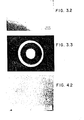
- Fig. 3.2 reveals the amorphous character of the sample and shows no crystallites.
- Fig. 3.3 is an electron diffraction (ED) pattern for the as cast sample. This ED pattern exhibits a diffuse hollow ring which is characteristic of amorphous materials.
- Example 14 is an as cast alloy that was annealed at 620°C for one hour. This produced a microcrystalline structure.
- the crystallinity of the material is further illustrated by Fig. 4.2 which is a TEM micrograph and shows the material has a grain size of approx- ° imately 200 A.
- Fig. 4.2 shows the material to be a single-phase. The fact that the material is single-phase is further supported by the lack of additional peaks associated with a boride precipitate in the x-ray diffraction pattern of Fig. 4.1.
- Figure 4.3 shows an electron diffraction pattern for the material of Example 14.
- the pattern shows multiple rings which correspond to the simple FCC crystal structure of a nickel solid solution.
- Example 15 was made by heat treating an amorphous ribbon at 800°C for one hour. This heat treatment resulted in a crystallized material containing the equilibrium phases.
- Fig. 5.1 is the x-ray diffraction pattern for Example 15 and shows the nickel solid solution peaks and the additional peaks associated with the nickel-molybdenum-boron compound Mo 2 NiB 2 .
- Fig. 5.2 shows a TEH micrograph of Example 15. The electron micrograph shows the dark boride particles and the light nickel-molybdendum solid solution matrix.
- An ED pattern of the material of Example 15 is shown in Fig. 5.3. This diffraction pattern has multiple rings which indicate the crystalline nature of the material. Those rings which are substantially continuous result from the matrix of nickel-molybdenum solid solution while the discontinuous rings arise from the boride particles.
- the as cast alloy of Example 13 was characterized by using a differential scanning calorimeter and differential thermal analysis (DSC/DTA).
- the thermo scan is illustrated by curve C of Fig. 6.
- Two exothermo peaks at about 535°C and 740°C were observed. Both of these peaks were smooth indicating only one crystallization process occurred at each temperature.
- the 535°C peak results from the transformation of the amorphous state to a nickel solid solution crystalline state.
- the 740°C peak is associated with the precipitation of the nickel-molybdenum-boron compound.
- a DSC/DTA scan of the material of Example 14 is shown by curve D in Fig. 6 and differs from Example 13 shown by the curve C in that the 535°C peak has disappeared.
- the 740°C peak for curve D is substantially the same as the 740°C peak for curve C.
- the lack of the 535°C peak in curve D and the similarity in the 740°C peaks in curves C and D gives support to the fact that the transformation to the stable structure is a two stage process. The first stage results in the formation of a microcrystalline state while the second stage is the formation of the boride particles. For this reason, it is possible to form a microcrystalline material which is single phase and homogeneous.
- Example 15 When the material of Example 15 is examined by DSC/DTA, the analysis yields a smooth curve as is illustrated by curve E in Fig. 6 and does not have either the 535°C peak or the 740°C peak. The lack of peaks indicates that the material, when heat treated at 800°C, has fully transformed to the equilibrium phases.
- Example 17 the casting temperature was 1600°C and surface velocity of the wheel was 6500 feet per minute (33.02 m/s).
- the casting speed was increased thereby reducing the time the metal ribbon was in contact with the wheel and when the pouring temperature was increased so that the cooling rate of the ribbon was decreased, a microcrystalline structure resulted.
- the characterization of the alloy of Example 17 was comparable to the heat treated ribbon illustrated in Fig. 4.
- Examples 16 and 17 were heat treated at 1100°C for two hours and optical micrographs, as well as transmission electron micrographs, were taken.
- the optical microstructures for the heat treated amorphous and microcrystallized materials of Examples 16 and 17 are illustrated in Fig. 7.1 and 7.2 respectively.
- Fig. 7 shows that the microstructure of the material after heat treatment is independent of the state of the original material.
- the alloys were cast on a wheel caster as described in the earlier examples.
- the higher boron alloys, Examples 21, 22, 25 and 26, were cast at a temperature between 1600°C and 1650°C.
- the remaining alloys were cast at a temperature between about 1400°C and 1500°C.
- Powders were prepared by mechanically pulverizing the ribbons to produce the following distribution of particle sizes:
- the powders were consolidated by Hipping at 1100°C and with an applied pressure of 10OMPa (15000 psi) for a period of 2 hrs.
- the consolidated samples were then heat treated at a temperature adequate to fully solution the matrix.
- the alloys were given an age hardening treatment.
- the conditions for the solution treatment and aging treatment are given in Table 6.
- the first seven alloys showed an increase in hardness after the aging treatment while the latter two did not age harden.
- the first seven alloys fall within the age hardenable regions of Fig. 2.1 through Fig 2.3 while the remainder are outside these regions.
- Fig. 8 shows the x-ray diffraction pattern and an optical micrograph of the solution treated sample.
- a Ni-Mo solid solution which is primarliy nickel
- the ternary boride compound with the formula Mo 2 Ni B 2 .
- the optical microqraph in Fig. 8.2 reveals borides, that are approximately- 1 to 2 microns in size and are distributed in the grain boundaries.
- the hardness of this solution treated sample is Rc 48.
- Fig. 9 shows the x-ray diffraction scan and microstructure of Example 18 after it was solution treated and aged at 800°C for 4 hours.
- Extra peaks in the x-ray diffraction scan shown in Fig. 9.1 correspond to the d-spacings of the intermetallic compounds Ni 3 Mo and Ni 4 Mo. These lines appear in addition to the Ni-Mo solids solution and Mo 2 Ni B 2 boride lines shown in'Fig. 8.1.
- the microstructure is shown in Fig. 9.2 and does not seem changed when compared to that of the solution treated sample (see Fig. 8.2); however, the hardness of this aged sample increased to Rc 56.
- the age hardening process increases the hardness of the alloys, it decreases the toughness. This occurs because the matrix before age hardening is a tough nickel-molybdenum solid solution, and in the age hardened condition contains a hard brittle intermetallic phase.
- the difference in the ductility of these alloys is illustrated by the effect of age hardening on the impact strength.
- Ni 60 Mo 30 B 10 was tested for impact strength before and after age hardening. These results are reported in Table 7. For each case, the impact strength reported is an average of three samples. The tests were done under standard Charpy un-notched test conditions.
- An alloy of Ni 36 Fe 41 Mo 13 B 10 was prepared in powder form by the methods described above.
- the distribution in the powder size was as follows:
- Figure 10.10 is an electron micrograph.
- the dark regions are mostly the ternary borides which are of the form Mo 2 (Fe Ni) B 2 where the Fe and Ni are substitutional in the ternary boride.
- Figure 10.2 shows an optical micrograph of the structure. It can be seen that the borides are well dispersed throughout the material. It also should be noted that iron substitution for nickel in the boride tends to spherodize the boride.
- Ribbons of two of the alloys reported in Table 2 (Ni 82 Mo 8 B 10 and Ni 65 Mo 15 B 20 ) which lie outside the claimed invention were pulverized to powders with the maximum mesh size of 35 mesh and a distribution as follows:
- the Ni 82 Mo 8 B 10 has an incipient melting temperature of 1085°C.
- a sample weighing 10 gm was consolidated by hot pressing at a temperature of 1030°C, 55° below the incipient melting temperature to assure that incipient melting did not occur.
- the microstructure of this sample is shown in Fig. 11.1.
- the material is poorly consolidated; there are voids which appear as dark images as well as traces of the residual powder grain boundaries.
- Cutting tools were prepared from the following four alloys shown in Table 8.
- the cutting tools were fabricated into rods by Hipping the powder at 1100°C at a pressure of 100 MPa (15,000psi) for a period of 2 hours.
- the resulting consolidated materials were solution treated between 1050°C and 1200°C.
- the solution treated rods were machined to form a single point turning tool. Examples 32 and 33 were aged at the temperatures given in Table 5.
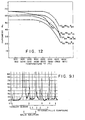
- the hot hardness of these materials as a function of temperature was determined for each of the alloys and is given in Fig. 12.
- the hot hardness of a M-42 high speed tool steel is also reported in Fig. 12.
- the composition of the M-42 steel is as follows:
- the cutting characteristics of the single point tools were tested by turning 4330 steel quenched and tempered to Brinell hardness 302.
- the feed rate was 0.10 inches per revolution, the cutting depth was 0.100 inches, and the cutting fluid was a soluable oil in water with a ratio of 1:20.
- the tool was considered a failure when there was 0.060 inches (0.15 cm) of wear.
- the results of these tests are given in Figure 13.
- the non-age hardenable materials in general performed as well as the M-42 high speed steel. Those alloys which were age hardenable were in general superior to the non-age hardenable materials and the high speed steel.
- a sample was made by thermo-mechanical processing of powders of a nickel base alloy having the composition Ni 56.5 Fe 10 Mo 23.5 B 10 , Powder of the above composition and with particle size less than 35 mesh was packed in a mild steel can and Hipped at temperatures between 1050°C-1100°C at a pressure of about 100 MPa (15,000psi) and held at temperature and pressure for about 2 hours.
- the resulting sample was decanned and tested for its physical properties at room temperture and elevated temperatures. The results are given in Table 9.
- the sample showed excellent hot hardness, hot strength and wear characteristics.
- Extrusion dies made of this material were field tested and compared against a commonly used conventional alloy Stellite 6. Dies made of the alloy of Example 34 offered more than twice the die life as was obtained by Stellite 6 for the extrusion of copper.
Landscapes
- Chemical & Material Sciences (AREA)
- Engineering & Computer Science (AREA)
- Materials Engineering (AREA)
- Mechanical Engineering (AREA)
- Metallurgy (AREA)
- Organic Chemistry (AREA)
- Manufacture Of Metal Powder And Suspensions Thereof (AREA)
- Powder Metallurgy (AREA)
Applications Claiming Priority (4)
| Application Number | Priority Date | Filing Date | Title |
|---|---|---|---|
| US06/220,618 US4533389A (en) | 1980-12-29 | 1980-12-29 | Boron containing rapid solidification alloy and method of making the same |
| US220618 | 1980-12-29 | ||
| US318893 | 1981-11-09 | ||
| US06/318,893 US4523950A (en) | 1980-12-29 | 1981-11-09 | Boron containing rapid solidification alloy and method of making the same |
Publications (2)
| Publication Number | Publication Date |
|---|---|
| EP0055829A2 true EP0055829A2 (fr) | 1982-07-14 |
| EP0055829A3 EP0055829A3 (fr) | 1982-07-28 |
Family
ID=26915024
Family Applications (1)
| Application Number | Title | Priority Date | Filing Date |
|---|---|---|---|
| EP81109912A Ceased EP0055829A3 (fr) | 1980-12-29 | 1981-11-26 | Alliage à solidification rapide, contenant du bore et procédé pour sa fabrication |
Country Status (5)
| Country | Link |
|---|---|
| US (1) | US4523950A (fr) |
| EP (1) | EP0055829A3 (fr) |
| KR (1) | KR830007866A (fr) |
| AU (1) | AU7902181A (fr) |
| CA (1) | CA1200123A (fr) |
Families Citing this family (1)
| Publication number | Priority date | Publication date | Assignee | Title |
|---|---|---|---|---|
| JP2660455B2 (ja) * | 1991-02-08 | 1997-10-08 | 東洋鋼鈑株式会社 | 耐熱硬質焼結合金 |
Family Cites Families (15)
| Publication number | Priority date | Publication date | Assignee | Title |
|---|---|---|---|---|
| US3856513A (en) * | 1972-12-26 | 1974-12-24 | Allied Chem | Novel amorphous metals and amorphous metal articles |
| US4067732A (en) * | 1975-06-26 | 1978-01-10 | Allied Chemical Corporation | Amorphous alloys which include iron group elements and boron |
| JPS5281006A (en) * | 1975-12-29 | 1977-07-07 | Kobe Steel Ltd | High speed steel made from powder containing nitrogen |
| US4116682A (en) * | 1976-12-27 | 1978-09-26 | Polk Donald E | Amorphous metal alloys and products thereof |
| US4152146A (en) * | 1976-12-29 | 1979-05-01 | Allied Chemical Corporation | Glass-forming alloys with improved filament strength |
| US4152144A (en) * | 1976-12-29 | 1979-05-01 | Allied Chemical Corporation | Metallic glasses having a combination of high permeability, low magnetostriction, low ac core loss and high thermal stability |
| US4221592A (en) * | 1977-09-02 | 1980-09-09 | Allied Chemical Corporation | Glassy alloys which include iron group elements and boron |
| US4133681A (en) * | 1978-01-03 | 1979-01-09 | Allied Chemical Corporation | Nickel-refractory metal-boron glassy alloys |
| US4133682A (en) * | 1978-01-03 | 1979-01-09 | Allied Chemical Corporation | Cobalt-refractory metal-boron glassy alloys |
| US4133679A (en) * | 1978-01-03 | 1979-01-09 | Allied Chemical Corporation | Iron-refractory metal-boron glassy alloys |
| US4210443A (en) * | 1978-02-27 | 1980-07-01 | Allied Chemical Corporation | Iron group transition metal-refractory metal-boron glassy alloys |
| US4365994A (en) * | 1979-03-23 | 1982-12-28 | Allied Corporation | Complex boride particle containing alloys |
| US4260666A (en) * | 1979-06-18 | 1981-04-07 | Allied Chemical Corporation | Brazed metal articles |
| US4318733A (en) * | 1979-11-19 | 1982-03-09 | Marko Materials, Inc. | Tool steels which contain boron and have been processed using a rapid solidification process and method |
| US4297135A (en) * | 1979-11-19 | 1981-10-27 | Marko Materials, Inc. | High strength iron, nickel and cobalt base crystalline alloys with ultrafine dispersion of borides and carbides |
-
1981
- 1981-11-09 US US06/318,893 patent/US4523950A/en not_active Expired - Lifetime
- 1981-11-26 EP EP81109912A patent/EP0055829A3/fr not_active Ceased
- 1981-12-23 CA CA000393125A patent/CA1200123A/fr not_active Expired
- 1981-12-24 AU AU79021/81A patent/AU7902181A/en not_active Abandoned
- 1981-12-28 KR KR1019810005178A patent/KR830007866A/ko not_active Ceased
Also Published As
| Publication number | Publication date |
|---|---|
| CA1200123A (fr) | 1986-02-04 |
| AU7902181A (en) | 1982-07-08 |
| US4523950A (en) | 1985-06-18 |
| EP0055829A3 (fr) | 1982-07-28 |
| KR830007866A (ko) | 1983-11-07 |
Similar Documents
| Publication | Publication Date | Title |
|---|---|---|
| US4582536A (en) | Production of increased ductility in articles consolidated from rapidly solidified alloy | |
| EP0339676B1 (fr) | Alliages d'aluminium à haute résistance et résistant à la chaleur | |
| US4359352A (en) | Nickel base superalloys which contain boron and have been processed by a rapid solidification process | |
| EP0675209B1 (fr) | Alliage à base d'aluminium à haute résistance | |
| EP3872197A1 (fr) | Alliage de cuivre composite comprenant un alliage à entropie élevée et son procédé de fabrication | |
| DE3043503A1 (de) | Kristalline metallegierung | |
| JP3142659B2 (ja) | 高力、耐熱アルミニウム基合金 | |
| EP0534470B1 (fr) | Matériau superplastique en alliage à base d'aluminium et procédé de fabrication | |
| JPS61130451A (ja) | 高い温度で高い強度をもつアルミニウム−鉄−バナジウム合金 | |
| EP0475101B1 (fr) | Alliages à base d'aluminium, à haute résistance | |
| US5607523A (en) | High-strength aluminum-based alloy | |
| EP0105595B1 (fr) | Alliages à base d'aluminium | |
| US4533389A (en) | Boron containing rapid solidification alloy and method of making the same | |
| EP0564814B1 (fr) | Matériau comprimé et stabilisé à partir d'un alliage à base d'aluminium à haute résistance mécanique et résistant à la chaleur et procédé de fabrication | |
| EP0540055B1 (fr) | Alliage à base d'aluminium à haute résistance mécanique et haute ténacité | |
| EP0503951B1 (fr) | Alliage d'aluminium resistant à l'usure et procédé pour son utilisation | |
| EP0474880B1 (fr) | Alliage d'aluminium et de chrome et production de cet alliage | |
| US4430115A (en) | Boron stainless steel powder and rapid solidification method | |
| US4473402A (en) | Fine grained cobalt-chromium alloys containing carbides made by consolidation of amorphous powders | |
| CN110193597B (zh) | 制造结晶铝-铁-硅合金的方法 | |
| US4523950A (en) | Boron containing rapid solidification alloy and method of making the same | |
| EP0514498B1 (fr) | Alliages au lithium-aluminium rapidement solidifies comportant du zirconium | |
| EP0534155B1 (fr) | Matériau compacté et consolidé en alliage à base d'aluminium et procédé de fabrication | |
| Grant | Structure and property control through rapid quenching of liquid metals and alloys | |
| EP0577944A1 (fr) | Alliage à base d'aluminium à haute résistance mécanique et matériau comprimé et stabilisé à partir de cet alliage |
Legal Events
| Date | Code | Title | Description |
|---|---|---|---|
| PUAI | Public reference made under article 153(3) epc to a published international application that has entered the european phase |
Free format text: ORIGINAL CODE: 0009012 |
|
| PUAL | Search report despatched |
Free format text: ORIGINAL CODE: 0009013 |
|
| AK | Designated contracting states |
Designated state(s): AT BE CH DE FR GB IT NL SE |
|
| AK | Designated contracting states |
Designated state(s): AT BE CH DE FR GB IT NL SE |
|
| 17P | Request for examination filed |
Effective date: 19820806 |
|
| STAA | Information on the status of an ep patent application or granted ep patent |
Free format text: STATUS: THE APPLICATION HAS BEEN REFUSED |
|
| 18R | Application refused |
Effective date: 19860727 |
|
| RIN1 | Information on inventor provided before grant (corrected) |
Inventor name: RONG, YAU WANG Inventor name: CHUNG-CHU, WAN Inventor name: DEEPAK, KAPOOR |