EP0055831A1 - Dispositif pour introduire des matériaux pulvérulents - Google Patents
Dispositif pour introduire des matériaux pulvérulents Download PDFInfo
- Publication number
- EP0055831A1 EP0055831A1 EP81110136A EP81110136A EP0055831A1 EP 0055831 A1 EP0055831 A1 EP 0055831A1 EP 81110136 A EP81110136 A EP 81110136A EP 81110136 A EP81110136 A EP 81110136A EP 0055831 A1 EP0055831 A1 EP 0055831A1
- Authority
- EP
- European Patent Office
- Prior art keywords
- screw
- chamber
- housing
- conveyed
- return valve
- Prior art date
- Legal status (The legal status is an assumption and is not a legal conclusion. Google has not performed a legal analysis and makes no representation as to the accuracy of the status listed.)
- Granted
Links
- 239000000463 material Substances 0.000 title claims abstract description 20
- 239000000843 powder Substances 0.000 title 1
- 238000005192 partition Methods 0.000 claims description 4
- 230000000694 effects Effects 0.000 abstract description 5
- 239000004568 cement Substances 0.000 abstract 1
- 235000013312 flour Nutrition 0.000 abstract 1
- 238000009423 ventilation Methods 0.000 description 6
- 238000009825 accumulation Methods 0.000 description 3
- 238000007789 sealing Methods 0.000 description 3
- 238000013022 venting Methods 0.000 description 3
- 241000237858 Gastropoda Species 0.000 description 2
- 238000005265 energy consumption Methods 0.000 description 1
- 230000002349 favourable effect Effects 0.000 description 1
- 238000012423 maintenance Methods 0.000 description 1
- 239000003566 sealing material Substances 0.000 description 1
Images
Classifications
-
- B—PERFORMING OPERATIONS; TRANSPORTING
- B65—CONVEYING; PACKING; STORING; HANDLING THIN OR FILAMENTARY MATERIAL
- B65G—TRANSPORT OR STORAGE DEVICES, e.g. CONVEYORS FOR LOADING OR TIPPING, SHOP CONVEYOR SYSTEMS OR PNEUMATIC TUBE CONVEYORS
- B65G33/00—Screw or rotary spiral conveyors
- B65G33/24—Details
-
- B—PERFORMING OPERATIONS; TRANSPORTING
- B65—CONVEYING; PACKING; STORING; HANDLING THIN OR FILAMENTARY MATERIAL
- B65G—TRANSPORT OR STORAGE DEVICES, e.g. CONVEYORS FOR LOADING OR TIPPING, SHOP CONVEYOR SYSTEMS OR PNEUMATIC TUBE CONVEYORS
- B65G53/00—Conveying materials in bulk through troughs, pipes or tubes by floating the materials or by flow of gas, liquid or foam
- B65G53/34—Details
- B65G53/40—Feeding or discharging devices
- B65G53/48—Screws or like rotary conveyors
Definitions
- the invention relates to a device for introducing pulverulent material into a pressurized delivery line through a cantilevered screw, the screw housing of which is extended beyond the end of the screw to a non-return valve arranged at the beginning of the delivery line.
- the sealing against the delivery line which is under higher pressure, is carried out by a relatively large - (long) plug.
- a relatively large - (long) plug In spite of this long plug, excessive energy consumption is avoided, since that occurring in a cylindrical tube Wedge effect in the conveying direction is prevented.
- the screw is essentially a feeding and venting device, so that the screw can be made short. It is not necessary to support the screw on both sides. The snail is therefore simply constructed and still runs smoothly.
- the stopper in the expanding chamber according to the invention never gets empty, because the pressure in the delivery line compresses the stopper and back when no material to be conveyed is pushed through the screw. It is practically possible to terminate the pressure at zero load.
- the min-load ratio is also favorable.
- a stuffing box in the pressure chamber as is required when the screw is supported on both sides, is avoided.
- the end of the screw is easily accessible, so that this end, where significant wear occurs, can be easily replaced. This accessibility and interchangeability also applies to other wear parts.
- the snail runs smoothly because it is relatively short. Warehouse- . problems caused by vibrations do not occur.
- the extension can be formed in a variety of ways, for example also by and / or with a shoulder adjacent to the screw. Venting takes place through the screw during conveyance. To support this ventilation, the inlet can be divided by a partition, which creates an extra ventilation.
- the screw Since the screw is only supported on one side (at the inlet), it is possible to arrange the check valve on the end face at the corresponding end of the expanding chamber, namely by means of an angle lever such that practically a parallel opening takes place, i.e. the ring-shaped cross-section that arises when the non-return valve is opened is approximately the same size over the entire circumference, which prevents uneven loading and enables the material to be conveyed out evenly.
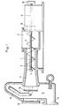
- the device shown in the drawing consists of a screw housing 1, in which a screw 2 is rotatably mounted.
- the discharge end 3 of the screw is exchangeable.
- a screw 4 is provided for this purpose.
- the inlet 5 can be divided by a partition 6 to create a vent 7.
- a stuffing box 8 for the drive shaft 9 seals the worm housing against this area.
- the drive is designated 10.
- a - in this embodiment - conically widening chamber 11 At the discharge end of the screw is a - in this embodiment - conically widening chamber 11.
- the chamber 11 opens into a space 13, which establishes the connection with the delivery line 12 and receives the check valve 14 with its angle lever 15.
- a 'cover which is essentially used for assembly and maintenance, is designated 16.
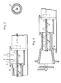
- a ventilation groove 17 is shown, which can provide better ventilation if this is desired.
- FIG 3 shows a differently designed chamber 11 with a shoulder 18 adjacent to the screw.
- the material to be conveyed is entered at 5 and pressed into the chamber 11 by the screw 2.
- the material is conveyed against the non-return valve with continuous conveying and supply of material into the conveying line 12, which has a higher pressure.
- the ventilation in this normal conveying takes place via the screw and the inlet.
- the partition 6 and optionally the vent groove 17 can support the venting.
- the pressure in the conveying line 12 compresses the material to be conveyed in the chamber 11 in the direction of the screw, so that a good and effective seal is produced here, but which is outside the range of action of the screw. If the conveyance now starts again, the material to be conveyed in the chamber 11 is pressurized in the opposite direction and the normal and desired conveyance begins without hindrance, since the chambers expand in the conveying direction and thus prevent a wedge effect in this direction.
- the check valve 14 is articulated by the angle lever 15 so that it opens “quasi parallel”, as shown in dashed lines. This creates a uniform ring-shaped opening cross-section.
Landscapes
- Engineering & Computer Science (AREA)
- Mechanical Engineering (AREA)
- Screw Conveyors (AREA)
- Air Transport Of Granular Materials (AREA)
- Check Valves (AREA)
- Filling Or Emptying Of Bunkers, Hoppers, And Tanks (AREA)
Applications Claiming Priority (2)
| Application Number | Priority Date | Filing Date | Title |
|---|---|---|---|
| DE3100050 | 1981-01-02 | ||
| DE3100050A DE3100050C2 (de) | 1981-01-02 | 1981-01-02 | Vorrichtung zum Einschleusen von pulverförmigem Gut |
Publications (2)
| Publication Number | Publication Date |
|---|---|
| EP0055831A1 true EP0055831A1 (fr) | 1982-07-14 |
| EP0055831B1 EP0055831B1 (fr) | 1985-11-21 |
Family
ID=6122193
Family Applications (1)
| Application Number | Title | Priority Date | Filing Date |
|---|---|---|---|
| EP81110136A Expired EP0055831B1 (fr) | 1981-01-02 | 1981-12-04 | Dispositif pour introduire des matériaux pulvérulents |
Country Status (7)
| Country | Link |
|---|---|
| US (1) | US4473327A (fr) |
| EP (1) | EP0055831B1 (fr) |
| CA (1) | CA1179707A (fr) |
| DE (2) | DE3100050C2 (fr) |
| DK (1) | DK151949C (fr) |
| ES (1) | ES508484A0 (fr) |
| ZA (1) | ZA818483B (fr) |
Cited By (3)
| Publication number | Priority date | Publication date | Assignee | Title |
|---|---|---|---|---|
| EP0287708A3 (fr) * | 1987-04-22 | 1990-01-10 | Color Service Srl | Dispositif automatique de pesage pour produits en poudre |
| WO2001005691A1 (fr) | 1999-07-19 | 2001-01-25 | Möller-Fuller Bulk Handling Gmbh | Dispositif d'alimentation en materiau sous forme de fines particules ou de poudre |
| CN110963249A (zh) * | 2019-10-28 | 2020-04-07 | 安徽神力运输机械有限公司 | 一种应用于水平螺旋输送机上的清堵机构 |
Families Citing this family (7)
| Publication number | Priority date | Publication date | Assignee | Title |
|---|---|---|---|---|
| DE3565507D1 (en) * | 1984-11-26 | 1988-11-17 | Alusuisse | Utilisation of a device for conveying flowing materials |
| US4881862A (en) * | 1987-09-30 | 1989-11-21 | Jenike & Johanson, Inc. | Screw seal |
| ITMI20050036A1 (it) * | 2005-01-14 | 2006-07-15 | Ecodeco S R L | Dispositivo per l'alimentazione di combustibili derivati dai rifiuti cdr ad impianti di combustione |
| US8087851B1 (en) * | 2006-04-27 | 2012-01-03 | Jarvis R Darren | Process for handling powdered material |
| PL2200915T3 (pl) * | 2007-10-18 | 2013-12-31 | Basf Se | Sposób zwilżania materiału w postaci cząstek |
| CN106743752B (zh) * | 2016-12-15 | 2019-03-08 | 中国人民解放军防化学院 | 一种用于气压分散的粉体储存与输送装置 |
| CN111483775A (zh) * | 2020-04-16 | 2020-08-04 | 徐州市宏星肥业有限公司 | 一种复合肥生产用物料自动供给装置 |
Citations (3)
| Publication number | Priority date | Publication date | Assignee | Title |
|---|---|---|---|---|
| DE1249763B (fr) * | 1967-09-07 | |||
| DE2729863A1 (de) * | 1976-07-05 | 1978-01-12 | Stabilator Ab | Verfahren und vorrichtung zur rohrfoerderung von materialien |
| DE2507687C3 (de) * | 1975-02-22 | 1979-11-15 | Claudius Peters Ag, 2000 Hamburg | Vorrichtung zum kontinuierlichen Fördern von pulverförmigem und grießigem Material |
Family Cites Families (2)
| Publication number | Priority date | Publication date | Assignee | Title |
|---|---|---|---|---|
| US1731455A (en) * | 1928-01-16 | 1929-10-15 | Int Comb Eng Corp | Transporter |
| US2290809A (en) * | 1941-05-15 | 1942-07-21 | Fuller Co | Dust spraying apparatus |
-
1981
- 1981-01-02 DE DE3100050A patent/DE3100050C2/de not_active Expired
- 1981-12-04 DE DE8181110136T patent/DE3173024D1/de not_active Expired
- 1981-12-04 EP EP81110136A patent/EP0055831B1/fr not_active Expired
- 1981-12-07 ZA ZA818483A patent/ZA818483B/xx unknown
- 1981-12-09 US US06/329,041 patent/US4473327A/en not_active Expired - Lifetime
- 1981-12-18 CA CA000392715A patent/CA1179707A/fr not_active Expired
- 1981-12-22 DK DK568681A patent/DK151949C/da not_active IP Right Cessation
- 1981-12-31 ES ES81508484A patent/ES508484A0/es active Granted
Patent Citations (3)
| Publication number | Priority date | Publication date | Assignee | Title |
|---|---|---|---|---|
| DE1249763B (fr) * | 1967-09-07 | |||
| DE2507687C3 (de) * | 1975-02-22 | 1979-11-15 | Claudius Peters Ag, 2000 Hamburg | Vorrichtung zum kontinuierlichen Fördern von pulverförmigem und grießigem Material |
| DE2729863A1 (de) * | 1976-07-05 | 1978-01-12 | Stabilator Ab | Verfahren und vorrichtung zur rohrfoerderung von materialien |
Cited By (5)
| Publication number | Priority date | Publication date | Assignee | Title |
|---|---|---|---|---|
| EP0287708A3 (fr) * | 1987-04-22 | 1990-01-10 | Color Service Srl | Dispositif automatique de pesage pour produits en poudre |
| US5006995A (en) * | 1987-04-22 | 1991-04-09 | Color Service S.R.L. | Automatic weighing plant for dyes in powder form |
| WO2001005691A1 (fr) | 1999-07-19 | 2001-01-25 | Möller-Fuller Bulk Handling Gmbh | Dispositif d'alimentation en materiau sous forme de fines particules ou de poudre |
| CN110963249A (zh) * | 2019-10-28 | 2020-04-07 | 安徽神力运输机械有限公司 | 一种应用于水平螺旋输送机上的清堵机构 |
| CN110963249B (zh) * | 2019-10-28 | 2021-05-07 | 安徽神力运输机械有限公司 | 一种应用于水平螺旋输送机上的清堵机构 |
Also Published As
| Publication number | Publication date |
|---|---|
| US4473327A (en) | 1984-09-25 |
| ES8302590A1 (es) | 1982-12-01 |
| DK568681A (da) | 1982-07-03 |
| DK151949B (da) | 1988-01-18 |
| DE3100050A1 (de) | 1982-07-22 |
| DE3173024D1 (en) | 1986-01-02 |
| ES508484A0 (es) | 1982-12-01 |
| ZA818483B (en) | 1982-10-27 |
| DK151949C (da) | 1988-07-25 |
| CA1179707A (fr) | 1984-12-18 |
| DE3100050C2 (de) | 1983-07-07 |
| EP0055831B1 (fr) | 1985-11-21 |
Similar Documents
| Publication | Publication Date | Title |
|---|---|---|
| DE2751773C2 (de) | Einrichtung zum Fördern von festem, partikelförmigen Material | |
| EP0055831B1 (fr) | Dispositif pour introduire des matériaux pulvérulents | |
| EP0017863A1 (fr) | Pompe à dosage | |
| DE2331585B2 (de) | Exzenterschneckenpumpe | |
| EP0098340B1 (fr) | Pompe à hélice dont l'arbre est supporté à ses deux extrémités | |
| DE3029872A1 (de) | Verfahren und vorrichtung zum pumpen fliessfaehigen materials | |
| EP0012795B1 (fr) | Boudineuse à vis pour le travail de matières plastiques, de caoutchouc ou analogues | |
| DE3317467A1 (de) | Vorrichtung und verfahren fuer den transport verschiedener materialarten in einer transportroehre | |
| DE2735180C2 (de) | Schüttgutbehälter für partikelförmiges Feststoffmaterial | |
| DE3013091A1 (de) | Vorrichtung zum entwaessern und verdichtung von rechengut, muell o.dgl. | |
| DE3145600A1 (de) | Vorrichtung an saugluftfoerderern zur kontinuierlichen foerderung von schuettgut | |
| DE2435625C3 (de) | Rohrleitungssystem zur pneumatischen Förderung von Schutt- oder Mahlgut | |
| EP0075137B1 (fr) | Convoyeur | |
| DE2165855A1 (de) | Abdichtende foerdervorrichtung | |
| DE9215464U1 (de) | Pumpeinrichtung für pastöse Medien | |
| DE2456476B1 (de) | Vorrichtung zum kontinuierlichen foerdern von pulverfoermigem und griessigem schuettgut | |
| EP0636560A1 (fr) | Pompe à hélice avec grille de déflexion pour convoyer continûment de la matière en vrac ou pulvérulente | |
| DE2137278C3 (de) | Absperrschieber für Füllmaschinen | |
| DE69713140T2 (de) | Vorrichtung zum fortlaufenden schleifen in einem holzschleifer | |
| DE3432456C2 (de) | Pumpe zum Fördern eines flüssigen oder zähflüssigen Mediums | |
| AT252040B (de) | Hydraulisch angetriebene Zwillingskolbenpumpe für breiige Stoffe, insbesondere für Beton | |
| DE4313888A1 (de) | Reaktor zur Zerlegung von Altpapier | |
| DE19611079C2 (de) | Feststoffpumpe zur Förderung plastischer Dickstoffe aus einem Druckraum | |
| DE3036280A1 (de) | Ruehrwerksmuehle | |
| DE2048328C (de) | Vorrichtung zur Abgabe von geschmolzenem Metall aus einem Reservoir an eine Gießmaschine |
Legal Events
| Date | Code | Title | Description |
|---|---|---|---|
| PUAI | Public reference made under article 153(3) epc to a published international application that has entered the european phase |
Free format text: ORIGINAL CODE: 0009012 |
|
| AK | Designated contracting states |
Designated state(s): CH DE FR GB IT SE |
|
| 17P | Request for examination filed |
Effective date: 19820714 |
|
| ITF | It: translation for a ep patent filed | ||
| GRAA | (expected) grant |
Free format text: ORIGINAL CODE: 0009210 |
|
| AK | Designated contracting states |
Designated state(s): CH DE FR GB IT LI SE |
|
| REF | Corresponds to: |
Ref document number: 3173024 Country of ref document: DE Date of ref document: 19860102 |
|
| ET | Fr: translation filed | ||
| PLBE | No opposition filed within time limit |
Free format text: ORIGINAL CODE: 0009261 |
|
| STAA | Information on the status of an ep patent application or granted ep patent |
Free format text: STATUS: NO OPPOSITION FILED WITHIN TIME LIMIT |
|
| 26N | No opposition filed | ||
| ITTA | It: last paid annual fee | ||
| EAL | Se: european patent in force in sweden |
Ref document number: 81110136.9 |
|
| PGFP | Annual fee paid to national office [announced via postgrant information from national office to epo] |
Ref country code: DE Payment date: 19961022 Year of fee payment: 16 |
|
| PGFP | Annual fee paid to national office [announced via postgrant information from national office to epo] |
Ref country code: FR Payment date: 19961118 Year of fee payment: 16 |
|
| PGFP | Annual fee paid to national office [announced via postgrant information from national office to epo] |
Ref country code: GB Payment date: 19961120 Year of fee payment: 16 |
|
| PGFP | Annual fee paid to national office [announced via postgrant information from national office to epo] |
Ref country code: SE Payment date: 19961219 Year of fee payment: 16 |
|
| PGFP | Annual fee paid to national office [announced via postgrant information from national office to epo] |
Ref country code: CH Payment date: 19961220 Year of fee payment: 16 |
|
| PG25 | Lapsed in a contracting state [announced via postgrant information from national office to epo] |
Ref country code: GB Free format text: LAPSE BECAUSE OF NON-PAYMENT OF DUE FEES Effective date: 19971204 |
|
| PG25 | Lapsed in a contracting state [announced via postgrant information from national office to epo] |
Ref country code: SE Free format text: LAPSE BECAUSE OF NON-PAYMENT OF DUE FEES Effective date: 19971205 |
|
| PG25 | Lapsed in a contracting state [announced via postgrant information from national office to epo] |
Ref country code: LI Free format text: LAPSE BECAUSE OF NON-PAYMENT OF DUE FEES Effective date: 19971231 Ref country code: FR Free format text: THE PATENT HAS BEEN ANNULLED BY A DECISION OF A NATIONAL AUTHORITY Effective date: 19971231 Ref country code: CH Free format text: LAPSE BECAUSE OF NON-PAYMENT OF DUE FEES Effective date: 19971231 |
|
| GBPC | Gb: european patent ceased through non-payment of renewal fee |
Effective date: 19971204 |
|
| REG | Reference to a national code |
Ref country code: CH Ref legal event code: PL |
|
| PG25 | Lapsed in a contracting state [announced via postgrant information from national office to epo] |
Ref country code: DE Free format text: LAPSE BECAUSE OF NON-PAYMENT OF DUE FEES Effective date: 19980901 |
|
| EUG | Se: european patent has lapsed |
Ref document number: 81110136.9 |
|
| REG | Reference to a national code |
Ref country code: FR Ref legal event code: ST |