EP0055901B1 - Ventilantriebsschmierung für eine Brennkraftmaschine - Google Patents
Ventilantriebsschmierung für eine Brennkraftmaschine Download PDFInfo
- Publication number
- EP0055901B1 EP0055901B1 EP81305842A EP81305842A EP0055901B1 EP 0055901 B1 EP0055901 B1 EP 0055901B1 EP 81305842 A EP81305842 A EP 81305842A EP 81305842 A EP81305842 A EP 81305842A EP 0055901 B1 EP0055901 B1 EP 0055901B1
- Authority
- EP
- European Patent Office
- Prior art keywords
- engine
- oil
- case
- filter means
- additional filter
- Prior art date
- Legal status (The legal status is an assumption and is not a legal conclusion. Google has not performed a legal analysis and makes no representation as to the accuracy of the status listed.)
- Expired
Links
- 238000005461 lubrication Methods 0.000 title claims abstract description 15
- 238000002485 combustion reaction Methods 0.000 title claims abstract description 8
- 239000007921 spray Substances 0.000 claims abstract description 21
- 210000002445 nipple Anatomy 0.000 claims abstract description 6
- 239000003921 oil Substances 0.000 claims description 26
- 239000002245 particle Substances 0.000 claims description 6
- 239000010687 lubricating oil Substances 0.000 claims description 3
- 239000007787 solid Substances 0.000 claims description 3
- 238000007789 sealing Methods 0.000 claims 1
- 238000011144 upstream manufacturing Methods 0.000 claims 1
- NJPPVKZQTLUDBO-UHFFFAOYSA-N novaluron Chemical compound C1=C(Cl)C(OC(F)(F)C(OC(F)(F)F)F)=CC=C1NC(=O)NC(=O)C1=C(F)C=CC=C1F NJPPVKZQTLUDBO-UHFFFAOYSA-N 0.000 description 6
- 239000010705 motor oil Substances 0.000 description 3
- 238000005219 brazing Methods 0.000 description 2
- 238000005096 rolling process Methods 0.000 description 2
- 238000005507 spraying Methods 0.000 description 2
- 230000000903 blocking effect Effects 0.000 description 1
- 230000006835 compression Effects 0.000 description 1
- 238000007906 compression Methods 0.000 description 1
- 238000005520 cutting process Methods 0.000 description 1
- 230000001419 dependent effect Effects 0.000 description 1
- 239000003599 detergent Substances 0.000 description 1
- 231100001261 hazardous Toxicity 0.000 description 1
- 235000003642 hunger Nutrition 0.000 description 1
- 230000000266 injurious effect Effects 0.000 description 1
- 230000001050 lubricating effect Effects 0.000 description 1
- 238000012423 maintenance Methods 0.000 description 1
- 238000004519 manufacturing process Methods 0.000 description 1
- 238000007790 scraping Methods 0.000 description 1
Images

Classifications
-
- F—MECHANICAL ENGINEERING; LIGHTING; HEATING; WEAPONS; BLASTING
- F01—MACHINES OR ENGINES IN GENERAL; ENGINE PLANTS IN GENERAL; STEAM ENGINES
- F01M—LUBRICATING OF MACHINES OR ENGINES IN GENERAL; LUBRICATING INTERNAL COMBUSTION ENGINES; CRANKCASE VENTILATING
- F01M11/00—Component parts, details or accessories, not provided for in, or of interest apart from, groups F01M1/00 - F01M9/00
- F01M11/02—Arrangements of lubricant conduits
-
- F—MECHANICAL ENGINEERING; LIGHTING; HEATING; WEAPONS; BLASTING
- F01—MACHINES OR ENGINES IN GENERAL; ENGINE PLANTS IN GENERAL; STEAM ENGINES
- F01M—LUBRICATING OF MACHINES OR ENGINES IN GENERAL; LUBRICATING INTERNAL COMBUSTION ENGINES; CRANKCASE VENTILATING
- F01M11/00—Component parts, details or accessories, not provided for in, or of interest apart from, groups F01M1/00 - F01M9/00
- F01M11/03—Mounting or connecting of lubricant purifying means relative to the machine or engine; Details of lubricant purifying means
-
- F—MECHANICAL ENGINEERING; LIGHTING; HEATING; WEAPONS; BLASTING
- F01—MACHINES OR ENGINES IN GENERAL; ENGINE PLANTS IN GENERAL; STEAM ENGINES
- F01M—LUBRICATING OF MACHINES OR ENGINES IN GENERAL; LUBRICATING INTERNAL COMBUSTION ENGINES; CRANKCASE VENTILATING
- F01M9/00—Lubrication means having pertinent characteristics not provided for in, or of interest apart from, groups F01M1/00 - F01M7/00
- F01M9/10—Lubrication of valve gear or auxiliaries
-
- F—MECHANICAL ENGINEERING; LIGHTING; HEATING; WEAPONS; BLASTING
- F01—MACHINES OR ENGINES IN GENERAL; ENGINE PLANTS IN GENERAL; STEAM ENGINES
- F01M—LUBRICATING OF MACHINES OR ENGINES IN GENERAL; LUBRICATING INTERNAL COMBUSTION ENGINES; CRANKCASE VENTILATING
- F01M9/00—Lubrication means having pertinent characteristics not provided for in, or of interest apart from, groups F01M1/00 - F01M7/00
- F01M9/10—Lubrication of valve gear or auxiliaries
- F01M9/105—Lubrication of valve gear or auxiliaries using distribution conduits
Definitions
- This invention relates to an internal combustion engine having an overhead camshaft to parts of which lubrication is applied by spraying.
- Lubrication of the interface between each cam of an overhead camshaft and the component against which the cam operates e.g. valve stem, tappet, rocker, ultimately controlling the aspiration valves of an internal combustion engine, is often effected by spraying.
- the primary objective of such lubrication is to direct a spray of oil on to an intended area of the cam and/or the component against which the cam directly operates. Effective lubrication of the said interface is mainly dependent on maintaining a sufficient oil spray onto the intended area.
- the spray is usually emitted from a small hole or jet in a conduit situated conveniently near the said area and fed from the engine oil pump by pipes and/or oilways in the cylinder block and head.
- An average engine oil filter is effective in preventing the flow, in the general oil circuits, of particles which would be injurious to sleeve and rolling bearings. However, it does allow to pass minute particles which in time, become coagulated on the walls of pipes or oilways to form areas of "crust".
- the said pieces may become dislodged purely by the flow of oil in the pipes or oilways, but their incidence is enhanced by the addition of or change to a higher detergent oil than normally used. This is particularly noticeable after the engine has been "flushed out”.
- An object of the present invention is to provide an O.H.C. internal combustion engine wherein this problem is obviated or minimised.
- the invention provides an internal combustion engine having an overhead camshaft and a lubrication system including an oil reservoir, a pump and a filter for supplying filtered lubricating oil to desired parts of the engine, the lubrication system including a plurality of apertures whence oil is pumped to lubricate cam surface of the camshaft, characterised in that additional filter means is provided in the oil flow to the apertures to discourage or prevent solid particles or matter from reaching the apertures and causing total or partial blockage thereof.
- the additional filter means should be positioned as far downstream in the oil stream flow as conditions allow; preferably in the final stage, just before the spray holes, in order to minimise the likelihood of blockage.
- the chosen example of engine of the invention is the British Ford Petrol engine 1600 OHC or 2000 OCH currently in production.
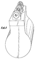
- camshaft lubrication oil ascends from the engine oil pump and filter, both situated low near the sump, through an oilway in the cylinder block, through a perforation in the cylinder head gasket, through an oilway in the cylinder head into the camshaft centre bearing pedestal from which it passes through a horizontally drilled oilway into the spray pipe assembly (Fig. 2).
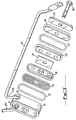
- Fig. 2 is a pictorial view of an assembly consisting of a spray pipe 10, nipple 11 and bracket 12.
- the assembly is that Ford Part which in U.K. is given No. 1490126 and which in Europe and U.S.A. is marked 70 HM 6578AE and DIFZ-6578A respectively.
- the assembly is secured by a bolt 13 to the side of the camshaft centre bearing pedestal 14 (Fig. 2a) while the nipple 11 enters a horizontally drilled oilway 15, to receive and transmit oil to the pipe 10. From this point oil flows into the fore and aft halves of the pipe 10a 10b finally to emerge as a spray 16 from each of eight spray holes 17, one spray lubricating each of each cams (not illustrated).
- the ends 18 of the pipe are sealed, and secured by one bolt each (not shown) to the camshaft force and aft bearing pedestals (also not shown).
- Another hazardous feature of this particular engine lies in the fact that the oil passes from an oilway in the cylinder block to an oilway in the cylinder head via the cylinder head gasket. Therefore, very special care must be taken, when changing the cylinder head gasket for maintenance purposes, that foreign matter, such as scrapings does not enter the oilway in either the cylinder block or the cylinder head, for on restarting the engine, such matter could be carried along by the oil and block one or more of the spray holes.
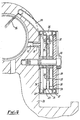
- Filter components are assembled in the case (1) in the following order:
- This assembly is then secured to the camshaft centre bearing pedestal by a bolt 30 which may be tightened solidly and yet apply a dimensionally controlled compression to the two '0' ring seals 22, 27 because of the limit to its movement imposed by the solid centre parts of the various components forming a stack around it.
- a nipple 31 on the case 21 enters the horizontally drilled hole 15 (Fig. 4) in the camshaft centre bearing pedestal 33 to admit oil to the filter case 21.
- the ends of the pipes 20a, 20b are secured as before to the camshaft fore and aft bearing pedestals (not shown).
Landscapes
- Engineering & Computer Science (AREA)
- Mechanical Engineering (AREA)
- General Engineering & Computer Science (AREA)
- Valve-Gear Or Valve Arrangements (AREA)
- Lubrication Details And Ventilation Of Internal Combustion Engines (AREA)
- Lubrication Of Internal Combustion Engines (AREA)
Claims (8)
Priority Applications (1)
| Application Number | Priority Date | Filing Date | Title |
|---|---|---|---|
| AT81305842T ATE13579T1 (de) | 1980-12-29 | 1981-12-10 | Ventilantriebsschmierung fuer eine brennkraftmaschine. |
Applications Claiming Priority (2)
| Application Number | Priority Date | Filing Date | Title |
|---|---|---|---|
| GB8041356 | 1980-12-29 | ||
| GB8041356 | 1980-12-29 |
Publications (2)
| Publication Number | Publication Date |
|---|---|
| EP0055901A1 EP0055901A1 (de) | 1982-07-14 |
| EP0055901B1 true EP0055901B1 (de) | 1985-05-29 |
Family
ID=10518225
Family Applications (1)
| Application Number | Title | Priority Date | Filing Date |
|---|---|---|---|
| EP81305842A Expired EP0055901B1 (de) | 1980-12-29 | 1981-12-10 | Ventilantriebsschmierung für eine Brennkraftmaschine |
Country Status (3)
| Country | Link |
|---|---|
| EP (1) | EP0055901B1 (de) |
| AT (1) | ATE13579T1 (de) |
| DE (1) | DE3170777D1 (de) |
Families Citing this family (1)
| Publication number | Priority date | Publication date | Assignee | Title |
|---|---|---|---|---|
| US5472045A (en) * | 1994-07-29 | 1995-12-05 | Modine Manufacturing Company | Donut oil cooler with a reusable filter |
Family Cites Families (6)
| Publication number | Priority date | Publication date | Assignee | Title |
|---|---|---|---|---|
| US1938506A (en) * | 1932-07-05 | 1933-12-05 | Wellman Davis Milton | Valve guide lubricator |
| US2030646A (en) * | 1934-09-26 | 1936-02-11 | Longo Joseph | Lubricating device |
| FR1027936A (fr) * | 1949-11-21 | 1953-05-18 | Dispositif de lubrification pour soupapes supérieures de moteurs à combustion interne | |
| GB820878A (en) * | 1956-11-05 | 1959-09-30 | Continental Motors Corp | Lubrication system for internal combustion engines |
| DE2620480C2 (de) * | 1976-05-08 | 1984-03-01 | Mtu Motoren- Und Turbinen-Union Friedrichshafen Gmbh, 7990 Friedrichshafen | Schmierölversorgung |
| DE2843248C2 (de) * | 1978-10-04 | 1984-08-23 | Klöckner-Humboldt-Deutz AG, 5000 Köln | Schmierölkreislauf für eine Brennkraftmaschine |
-
1981
- 1981-12-10 AT AT81305842T patent/ATE13579T1/de active
- 1981-12-10 EP EP81305842A patent/EP0055901B1/de not_active Expired
- 1981-12-10 DE DE8181305842T patent/DE3170777D1/de not_active Expired
Also Published As
| Publication number | Publication date |
|---|---|
| EP0055901A1 (de) | 1982-07-14 |
| DE3170777D1 (en) | 1985-07-04 |
| ATE13579T1 (de) | 1985-06-15 |
Similar Documents
| Publication | Publication Date | Title |
|---|---|---|
| US3485324A (en) | Piston cooling system | |
| US5695637A (en) | Combination full flow and bypass filter with venturi nozzle | |
| DE19544533C2 (de) | Schmierungssystem für einen Viertaktmotor | |
| EP1065350B1 (de) | Brennkraftmaschine mit einer Entlüftungseinrichtung | |
| US4204487A (en) | Internal combustion engines | |
| US4615315A (en) | Oil cleaning assemblies for engines | |
| DE102012207829B4 (de) | Blowby-Strömungssteuersystem für einen turbogeladenen Motor | |
| DE102011008093B4 (de) | Schmieranlage für mit einem Turbolader ausgestatteten Motor | |
| WO2001004464A1 (de) | Hubkolbenbrennkraftmaschine mit einer nockenwelle | |
| DE69007816T2 (de) | Zweitaktbrennkraftmaschine mit Einrichtung zur direkten Schmierung. | |
| DE10336740B4 (de) | Kolbenkühlölsystem mit Ölhobel | |
| DE102009030556B4 (de) | Turboladersystem für einen Verbrennungsmotor mit einem Turbolader- Befestigungssockel mit verringerter Grundfläche | |
| DE10159104B4 (de) | Brennkraftmaschine | |
| US4430971A (en) | Internal combustion engine | |
| EP0251159B1 (de) | Rückführleitung für Leckgase aus dem Kurbelgehäuse | |
| EP0356641B1 (de) | Kühlvorrichtung für die im Zylinderkopf einer Brennkraftmaschine angeordneten Ventilsitzringe | |
| EP0055901A1 (de) | Ventilantriebsschmierung für eine Brennkraftmaschine | |
| DE102014102099B4 (de) | Motorbaugruppe mit einem Kurbelgehäuse-Zwangsentlüftungssystem | |
| EP0502692A1 (de) | Schmierung von Kolben einer Kraftstoffeinspritzpumpe | |
| EP0358861B1 (de) | Vorrichtung zum Reinigen von Schmieröl | |
| US5400752A (en) | Engine protection valve | |
| KR100539602B1 (ko) | 내연기관의 윤활유 통로구조 | |
| JPS59526A (ja) | 内燃機関のピストン冷却装置 | |
| JP2729646B2 (ja) | バーチカル型エンジンの潤滑装置 | |
| JPS6233930Y2 (de) |
Legal Events
| Date | Code | Title | Description |
|---|---|---|---|
| PUAI | Public reference made under article 153(3) epc to a published international application that has entered the european phase |
Free format text: ORIGINAL CODE: 0009012 |
|
| AK | Designated contracting states |
Designated state(s): AT BE CH DE FR GB IT LU NL SE |
|
| KL | Correction list |
Free format text: 82/05 |
|
| RBV | Designated contracting states (corrected) |
Designated state(s): AT BE CH DE FR GB IT LI LU NL SE |
|
| 17P | Request for examination filed |
Effective date: 19830104 |
|
| ITF | It: translation for a ep patent filed | ||
| GRAA | (expected) grant |
Free format text: ORIGINAL CODE: 0009210 |
|
| AK | Designated contracting states |
Designated state(s): AT BE CH DE FR GB IT LI LU NL SE |
|
| REF | Corresponds to: |
Ref document number: 13579 Country of ref document: AT Date of ref document: 19850615 Kind code of ref document: T |
|
| PG25 | Lapsed in a contracting state [announced via postgrant information from national office to epo] |
Ref country code: SE Effective date: 19850530 |
|
| REF | Corresponds to: |
Ref document number: 3170777 Country of ref document: DE Date of ref document: 19850704 |
|
| REG | Reference to a national code |
Ref country code: CH Ref legal event code: PL |
|
| ET | Fr: translation filed | ||
| PG25 | Lapsed in a contracting state [announced via postgrant information from national office to epo] |
Ref country code: GB Effective date: 19851210 Ref country code: AT Effective date: 19851210 |
|
| PG25 | Lapsed in a contracting state [announced via postgrant information from national office to epo] |
Ref country code: LU Free format text: LAPSE BECAUSE OF NON-PAYMENT OF DUE FEES Effective date: 19851231 |
|
| PLBI | Opposition filed |
Free format text: ORIGINAL CODE: 0009260 |
|
| 26 | Opposition filed |
Opponent name: MTU MOTOREN- UND TURBINEN-UNION FRIEDRICHSHAFEN GM Effective date: 19860218 |
|
| NLR1 | Nl: opposition has been filed with the epo |
Opponent name: MTU MOTOREN- UND TURBINEN-UNION FRIEDRICHSHAFEN GM |
|
| BERE | Be: lapsed |
Owner name: HOLDING NORMAN Effective date: 19851231 |
|
| PG25 | Lapsed in a contracting state [announced via postgrant information from national office to epo] |
Ref country code: NL Effective date: 19860701 |
|
| GBPC | Gb: european patent ceased through non-payment of renewal fee | ||
| NLV4 | Nl: lapsed or anulled due to non-payment of the annual fee | ||
| PG25 | Lapsed in a contracting state [announced via postgrant information from national office to epo] |
Ref country code: FR Free format text: LAPSE BECAUSE OF NON-PAYMENT OF DUE FEES Effective date: 19860829 |
|
| REG | Reference to a national code |
Ref country code: FR Ref legal event code: ST |
|
| RDAG | Patent revoked |
Free format text: ORIGINAL CODE: 0009271 |
|
| STAA | Information on the status of an ep patent application or granted ep patent |
Free format text: STATUS: PATENT REVOKED |
|
| GBPR | Gb: patent revoked under art. 102 of the ep convention designating the uk as contracting state | ||
| 27W | Patent revoked |
Effective date: 19880529 |
|
| REG | Reference to a national code |
Ref country code: CH Ref legal event code: PL |