EP0055905A1 - Talonnière pour fixation de ski pour la randonnée - Google Patents
Talonnière pour fixation de ski pour la randonnée Download PDFInfo
- Publication number
- EP0055905A1 EP0055905A1 EP81305886A EP81305886A EP0055905A1 EP 0055905 A1 EP0055905 A1 EP 0055905A1 EP 81305886 A EP81305886 A EP 81305886A EP 81305886 A EP81305886 A EP 81305886A EP 0055905 A1 EP0055905 A1 EP 0055905A1
- Authority
- EP
- European Patent Office
- Prior art keywords
- heel
- latch members
- latch
- ski
- beam means
- Prior art date
- Legal status (The legal status is an assumption and is not a legal conclusion. Google has not performed a legal analysis and makes no representation as to the accuracy of the status listed.)
- Withdrawn
Links
- 230000027455 binding Effects 0.000 title claims abstract description 29
- 238000009739 binding Methods 0.000 title claims abstract description 29
- 235000010627 Phaseolus vulgaris Nutrition 0.000 claims 1
- 244000046052 Phaseolus vulgaris Species 0.000 claims 1
- 210000002969 egg yolk Anatomy 0.000 description 26
- 239000000463 material Substances 0.000 description 6
- 239000004677 Nylon Substances 0.000 description 3
- 239000011521 glass Substances 0.000 description 3
- 229920001778 nylon Polymers 0.000 description 3
- 229920000642 polymer Polymers 0.000 description 3
- 239000000945 filler Substances 0.000 description 2
- 230000004048 modification Effects 0.000 description 2
- 238000012986 modification Methods 0.000 description 2
- JOYRKODLDBILNP-UHFFFAOYSA-N Ethyl urethane Chemical compound CCOC(N)=O JOYRKODLDBILNP-UHFFFAOYSA-N 0.000 description 1
- 229920006236 copolyester elastomer Polymers 0.000 description 1
- 238000004519 manufacturing process Methods 0.000 description 1
Images


Classifications
-
- A—HUMAN NECESSITIES
- A63—SPORTS; GAMES; AMUSEMENTS
- A63C—SKATES; SKIS; ROLLER SKATES; DESIGN OR LAYOUT OF COURTS, RINKS OR THE LIKE
- A63C9/00—Ski bindings
- A63C9/20—Non-self-releasing bindings with special sole edge holders instead of toe-straps
-
- A—HUMAN NECESSITIES
- A63—SPORTS; GAMES; AMUSEMENTS
- A63C—SKATES; SKIS; ROLLER SKATES; DESIGN OR LAYOUT OF COURTS, RINKS OR THE LIKE
- A63C9/00—Ski bindings
- A63C9/08—Ski bindings yieldable or self-releasing in the event of an accident, i.e. safety bindings
- A63C9/084—Ski bindings yieldable or self-releasing in the event of an accident, i.e. safety bindings with heel hold-downs, e.g. swingable
Definitions
- This invention relates to ski binding, and particularly; to heel bindings for cross-country skis to allow their use in a downhill mode.
- the ski shoe In the cross-country (also called Nordic) style of skiing, the ski shoe is secured to the ski only at the toe. This allows the so-called "kick and glide" motion for travelling over flat terrain when using the skis.
- the ski shoe or boot In the downhill (or Alpine) style of skiing, on the other hand, the ski shoe or boot is fixed firmly to the ski both at heel and toe. This allows the skier to transfer weight selectively and precisely to the skis and particularly the ski edges, thereby permitting greater control of the skis for turning and maneuvering.
- the cross-country ski generally being narrower, lighter and more flexible than the downhill ski, but the principal difference is in the binding of the skier's foot to the ski.
- the cross country skier may desire the control of his or her skis that a downhill-type binding would give.
- One way to accomplish this is to provide a means for fixing the heel of a cross-country ski shoe to the ski.
- the invention provides such a means.
- a heel binding for a cross-country ski comprises a base fixed to the ski, oppositely facing first and second latch mem- bers rotatably mounted on the base for movement from a first spaced apart position to a second position in which oppositely facing first and second latch surfaces close to releasably secure a heel portion, the latch members being biased in the open, first position, and spaced apart first and second flexible beams mounted on the base for movement between a first position in which the beams are out of operative contact with the latch members and a second position in which the beams flexibly hold the latch members in the second position.
- the latch surfaces include cam surface portions that are shaped to move the latch members outward against the resistance of the flexible beams and release the heel portion when substantial force is applied from the heel portion.
- a collar slidably mounted on the beams, so that the effective stiffness of the beams may be adjusted, a guide with a V-shaped groove aligned with the latch members, and having the latch members mounted for rotatable movement on axes parallel to the ski axis and the beams mounted on axes transverse to the ski axis, so that the beams engage outside surfaces of the latch members to operatively, slidingly engage the latch members to move them to their closed, second, position when the beams are moved to their second position.
- the heel binding 10 is secured to the cross-country ski 12 of the skier, adjacent the heel 14 of the skier's shoe 16.
- the skier's shoe 16 is modified by the application of a cup adapter 18 to the rear of the shoe to provide a rearwardly projecting pin 20 and to aid in transfer of force from the skier to the projecting pin, and ultimately the binding and ski.
- the pin 20 has a portion 22 embedded in the heel 14.
- Other, suitable, adapters may be applied to the shoe 16, or the shoe 16 may be manufactured and sold with a rearward projection, as part of the heel 14.
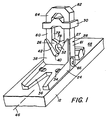
- the heel binding 10 which will cooperate with the pin 20, includes a base 24, cam latches 26 and 27, a yolk 28, and a collar 30 for the yolk.
- the base 24 of the heel binding 10 is fastened to the ski 12 with conventional flat head screws 34.
- the forward portion of the base 24 includes a forward, horizontal striker plate 36 for positioning under the ski shoe heel 14, and a substantially vertical guide plate 38 with an upturned V-shaped groove 40 having groove sides 42 for centering a downwardly thrust heel pin 20.
- the rear portion of the base 24 has a slot i 44 transverse to the ski axis 46 for receiving the cam latches 26, 27.
- the preferred material for the base 24 is 30% glass-filled nylon, although other polymers and fillers may be used.
- the cam latches 26, 27 are two opposing latches mounted in the base slot 44 for rotation about respective axes 48, 49 through their respective lower portions 50, 51.
- the cam latch axes 48, 49 are parallel to the ski axis 46.
- the cam latches 26, 27 are mounted for movement toward each other to achieve a closed . position (see Fig. 5), and away from each other to achieve an open position (see Fig. 4).
- the inner latch surface 52, 53 of each cam latch 26, 27 respectively is shaped to secure the heel pin 20 when the latches are together in the closed position.
- a spring 54 is located between the lower portions 50, 51 of the cam latches 26, 27 to bias them in the open position (Figs. 2 and 4) so that the heel pin 20 is free to move up or down.
- the outer surfaces 58, 59 of the cam latches 26, 27, respectively, extend outwardly when the cam latches are in the open position (Fig. 4), and are generally parallel when the cam latches are in the closed position (Fig. 5).
- the preferred material for the cam latches 26, 27 is also 30% glass-filled nylon, although other polymers and fillers may be used.
- the yolk 28 is a U-shaped piece with two parallel flexible beams 60, 61 joined by an endpiece 62 at one end 64 and rotatably mounted on the base 24 by way of pins 66 extending outwardly from the base 24 just above the top surface 68 of the ski 12 and forward of the cam latches 26, 27.
- the yolk 28 is rotat- : able, therefore, about an axis 70 transverse to the ski axis 46.
- the yolk 28 is movable between two positions, a first position in which the yolk 28 is down (see Fig. 2) and out of the way of the outside surfaces 58, 59 of the cam latches 26, 27 so that the cam latches can respond to the bias of the spring 54 and take an open position (see Fig.
- the yolk 28 is formed of material such as a copolyester elastomer or urethane, though other polymers will do, so that the arms 60, 61 of the yolk 28 are flexible and will flex outwardly, should a substantial force be exerted by the heel pin 20 captured between the cam latches 26, 27.
- the material used in the illustrated embodiment is that sold under the designation "Hytrel 55" by E.I. duPont de Nemours & Co., Inc. of Wilmington, Delaware.
- the upper portions of the inner surfaces 52, 53 of the cam latches 26, 27 form cam surfaces 76, 77, respectively, that are rounded to generally conform to the curvature of the pin 20.
- a gap 78 exists between the innermost parts 80, 81 of the cam surfaces 76, 77, that can widen enough as upward force by the pin 20 (indicated by the arrow 84) forces apart the cam latches 26, 27 against the yolk beams 60, 61, for the pin 20 to escape the cam latches 26, 27 entirely.
- the gap 78 is 1/8 inch
- the diameter of the pin 20 is 3/8 inch
- the distance between the inside surfaces 72, 73 of the beams 60, 61 is 1 1/16 inch.
- the yolk collar 30 is a sliding cross-piece made from 30% glass-filled nylon or similar material that fixes the relative spacing of the yolk beams 60, 61.
- the collar 30 is fitted about the yoke beams for snug manual sliding of the collar 30 up and down the beams.
- the relative position of the collar 30 determines the degree of stiffness of the portion of the beams 60, 61 between the collar .30 and the yolk pins 66 and, therefore, determines the amount of force by the heel pin 20 that will be necessary to force apart the cam latches 26, 27 to release the pin 20.
- the yolk 28 In operation of the ski 12 in the normal cross-country mode (see Figs. 2 and 4), the yolk 28 is in a first, downward, position.
- the yolk flexible beams 60, 61 are out of operative contact with the cam latches 26, 27, and the cam latches are accordingly in their open, first, position (see Fig. 4) in response to the spring 54 biasing them outwardly.
- the heel pin 20 is not restrained in any way against upward translation, and the skier's shoe 16 is movable in the typical cross-country mode.
- the heel pin 20 is directed to between the cam latches 26, 27, guided by the guide plate 38.
- the groove sides 42 forming the V-shaped groove 40 in the guide plate 38 guide the pin 20 to alignment with the cam latches 26, 27.
- the yolk 28 is moved upward, rotating about its axis 70.
- the inside surfaces 72, 73 of the flexible beams 60, 61 of the yolk 28 operatively and slidingly engage the outside surfaces 58, 59 of the cam latches 26, 27 urging the cam latches inward toward their second position in which the cam latch inside surfaces 52, 53 secure the heel pin 20 (see Fig. 5).
- the yolk flexible beams 60, 61 are in : their upward, second position (see Fig. 3), and the cam latches 26, 27 are in their closed, second, position (see Fig 5).
- the spacing between the flexible beams 60, 61 is chosen so that it is slightly less than the width of the cam latches 26, 27, providing a tension when the yolk 28 is in the second position that keeps the yolk in place.
- the pin can be released from the cam latches 26, 27.
- the yolk flexible beams 60, 61 will yield outwardly because of their flexibility if outward force is placed on the cam latches 26, 27.
- the upper cam surface portions 76, 77 of the cam latch inside surfaces 52, 53 are shaped so that a substantial force, generally upward, on the pin 20 will urge the latches 26, 27 outward and widen the gap 78 between the latches enough so that the pin will escape them.
- the amount of force necessary to release the pin 20 can be adjusted by varying the position of the yolk collar 30 along the length of the flexible beams 60, 61.
- the position of the yolk collar 30 is adjusted by manually sliding the collar 30 up or down the length of the beams 60, 61.
- the invention thus provides a quick and easy way to convert a cross-country ski to one that can be used in the downhill fashion by binding the heel of the cross-country skier's shoe to the ski.
- the yolk 28 is easily manipulated, and its operative position is easily determined at a glance.
- the shoe heel can be released, at an adjustable force, from the binding in the event of a fall, and that force is easily adjustable by manually positioning the yoke collar 30.
Landscapes
- Footwear And Its Accessory, Manufacturing Method And Apparatuses (AREA)
Applications Claiming Priority (2)
| Application Number | Priority Date | Filing Date | Title |
|---|---|---|---|
| US06/222,370 US4358131A (en) | 1981-01-05 | 1981-01-05 | Heel binding for cross-country skis |
| US222370 | 1981-01-05 |
Publications (1)
| Publication Number | Publication Date |
|---|---|
| EP0055905A1 true EP0055905A1 (fr) | 1982-07-14 |
Family
ID=22831919
Family Applications (1)
| Application Number | Title | Priority Date | Filing Date |
|---|---|---|---|
| EP81305886A Withdrawn EP0055905A1 (fr) | 1981-01-05 | 1981-12-15 | Talonnière pour fixation de ski pour la randonnée |
Country Status (3)
| Country | Link |
|---|---|
| US (1) | US4358131A (fr) |
| EP (1) | EP0055905A1 (fr) |
| CA (1) | CA1161868A (fr) |
Cited By (2)
| Publication number | Priority date | Publication date | Assignee | Title |
|---|---|---|---|---|
| WO1989002300A1 (fr) * | 1987-09-19 | 1989-03-23 | Heinz Beck | Dispositif de maintien du talon pour chaussures de ski de promenade et de randonnee |
| EP0666091A3 (fr) * | 1994-01-11 | 1996-01-24 | Hubert Boesch | Fixation de chaussures aux appareils de sport. |
Families Citing this family (12)
| Publication number | Priority date | Publication date | Assignee | Title |
|---|---|---|---|---|
| DE4142390C2 (de) * | 1991-08-05 | 1994-03-10 | Silvretta Sherpas Sportartikel | Sicherheitsbindung für Sprungski |
| US5971420A (en) * | 1994-06-06 | 1999-10-26 | Shimano, Inc. | Snowboard binding |
| US5660410A (en) * | 1994-12-09 | 1997-08-26 | Device Manufacturing Corporation | Strapless boot binding for snowboards |
| WO1998047583A1 (fr) | 1997-04-23 | 1998-10-29 | Jerry Fijalkowski | Repose-skis portable |
| US8328225B2 (en) * | 2009-07-24 | 2012-12-11 | Jason M Prigge | Ski binding adaptor with floating heel lock |
| US8733782B2 (en) * | 2010-10-15 | 2014-05-27 | BackCountry Garage, LLC | Hinge mechanism, collapsible ascension ski having such a hinge mechanism, and related methods and kits |
| DE102011082612A1 (de) * | 2011-09-13 | 2013-03-14 | SALEWA Sportgeräte GmbH | Ferseneinheit für eine Tourenbindung |
| EP3218073B1 (fr) | 2014-11-14 | 2021-05-19 | The Burton Corporation | Fixation de planche à neige |
| US9149711B1 (en) | 2014-11-14 | 2015-10-06 | The Burton Corporation | Snowboard binding and boot |
| US9220970B1 (en) | 2014-11-14 | 2015-12-29 | The Burton Corporation | Snowboard binding and boot |
| US10426221B2 (en) * | 2016-01-08 | 2019-10-01 | Nike, Inc. | Method and apparatus for dynamically altering a height of a sole assembly |
| US10758811B2 (en) | 2016-01-28 | 2020-09-01 | BackCountry Garage, LLC | Collapsible ski having fabric hinge |
Citations (5)
| Publication number | Priority date | Publication date | Assignee | Title |
|---|---|---|---|---|
| DE1578832A1 (de) * | 1966-07-01 | 1970-12-23 | Hannes Marker | Absatzhaltevorrichtung fuer Sicherheits-Skibindungen |
| US3985371A (en) * | 1974-12-23 | 1976-10-12 | Ski Safe Inc. | Touring ski boot heel binding |
| DE2808131A1 (de) * | 1978-02-25 | 1979-09-06 | Hans Glaser | Zusatzbindung fuer langlaufski |
| US4196921A (en) * | 1976-10-12 | 1980-04-08 | Sherwin William C | Cross-country ski boot restraining apparatus |
| FR2448912A1 (fr) * | 1979-02-19 | 1980-09-12 | Salomon & Fils F | Dispositif de maintien d'une chaussure de ski de fond ou de randonnee sur un ski |
Family Cites Families (16)
| Publication number | Priority date | Publication date | Assignee | Title |
|---|---|---|---|---|
| AT61783B (de) | 1912-12-12 | 1913-10-25 | Josef Madl | Einrichtung an Schneeschuhen zur Verhütung des seitlichen Rutschens des Fußes. |
| US2116969A (en) * | 1937-02-16 | 1938-05-10 | Jr George J Cyr | Heel plate for skiing |
| DE807789C (de) * | 1950-02-02 | 1951-07-05 | Franz Schwaerzler | Skibindung |
| AT173649B (de) | 1950-02-23 | 1953-01-10 | Julius Krusche | Wasserlaufschuh |
| CH303307A (de) | 1953-04-13 | 1954-11-30 | Zollinger Alfred | Zusätzliche Vertikalzugvorrichtung an Skibindungen. |
| US3398969A (en) * | 1965-12-06 | 1968-08-27 | Thomas E. Perry | Attachment for boot to adapt boot for use with ski binding |
| US3560011A (en) * | 1968-10-22 | 1971-02-02 | Spademan Richard George | Safety binding mechanism |
| US3618233A (en) * | 1969-11-12 | 1971-11-09 | Nils Eie | Arrangement concerning ski boots |
| AT319810B (de) * | 1971-03-25 | 1975-01-10 | Marker Hannes | Stabilisator für Skilanglaufschuhe |
| CH552399A (de) | 1973-11-02 | 1974-08-15 | Glaser Hans | Zusatzbindungsteil fuer langlaufski. |
| DE7428363U (de) * | 1974-08-21 | 1975-01-09 | Iser Iser H | Fersenbindung für Langlaufski |
| US3934893A (en) * | 1974-10-04 | 1976-01-27 | Greenleaf Joseph A | Slalom ski device |
| US3979131A (en) * | 1975-03-18 | 1976-09-07 | Ginther George E | Ski binding |
| US4113275A (en) * | 1976-10-12 | 1978-09-12 | Nortec Inc. | Ski boot heel restraining apparatus |
| US4154008A (en) * | 1977-10-25 | 1979-05-15 | Jacobs Thomas M | Heel plate arrangement for cross country ski boot |
| DE3207756C2 (de) * | 1982-03-04 | 1985-01-31 | Didier Engineering Gmbh, 4300 Essen | Herdwagen - Durchschubofen |
-
1981
- 1981-01-05 US US06/222,370 patent/US4358131A/en not_active Expired - Fee Related
- 1981-12-14 CA CA000392194A patent/CA1161868A/fr not_active Expired
- 1981-12-15 EP EP81305886A patent/EP0055905A1/fr not_active Withdrawn
Patent Citations (6)
| Publication number | Priority date | Publication date | Assignee | Title |
|---|---|---|---|---|
| DE1578832A1 (de) * | 1966-07-01 | 1970-12-23 | Hannes Marker | Absatzhaltevorrichtung fuer Sicherheits-Skibindungen |
| US3985371A (en) * | 1974-12-23 | 1976-10-12 | Ski Safe Inc. | Touring ski boot heel binding |
| US4196921A (en) * | 1976-10-12 | 1980-04-08 | Sherwin William C | Cross-country ski boot restraining apparatus |
| DE2808131A1 (de) * | 1978-02-25 | 1979-09-06 | Hans Glaser | Zusatzbindung fuer langlaufski |
| US4176856A (en) * | 1978-02-25 | 1979-12-04 | Glaser Hans E | Binding for cross-country skis |
| FR2448912A1 (fr) * | 1979-02-19 | 1980-09-12 | Salomon & Fils F | Dispositif de maintien d'une chaussure de ski de fond ou de randonnee sur un ski |
Cited By (2)
| Publication number | Priority date | Publication date | Assignee | Title |
|---|---|---|---|---|
| WO1989002300A1 (fr) * | 1987-09-19 | 1989-03-23 | Heinz Beck | Dispositif de maintien du talon pour chaussures de ski de promenade et de randonnee |
| EP0666091A3 (fr) * | 1994-01-11 | 1996-01-24 | Hubert Boesch | Fixation de chaussures aux appareils de sport. |
Also Published As
| Publication number | Publication date |
|---|---|
| US4358131A (en) | 1982-11-09 |
| CA1161868A (fr) | 1984-02-07 |
Similar Documents
| Publication | Publication Date | Title |
|---|---|---|
| US4358131A (en) | Heel binding for cross-country skis | |
| US4348036A (en) | Safety binding for nordic skis | |
| US8439389B2 (en) | Toe unit for alpine touring binding | |
| US6209903B1 (en) | Apparatus for attaching a gliding element to a shoe | |
| US5938228A (en) | Retention apparatus for a boot on a gliding board | |
| US3489424A (en) | Safety ski binding | |
| US4230338A (en) | Safety ski binding | |
| US5727808A (en) | Free heel/anterior release ski binding | |
| US4928988A (en) | Safety binding for a ski | |
| EP0192312A2 (fr) | Patin, en particulier patin à glace de grande vitesse | |
| US5794963A (en) | Binding device and a binding device/boot assembly | |
| US4679815A (en) | Safety ski binding | |
| EP0972545A1 (fr) | Fixation d'une chaussure sur une planche de glisse | |
| US3775872A (en) | Ski boot with latchable articulated leg holder | |
| US5957478A (en) | Release binding for telemark skiing, back country skiing, and ski jumping | |
| US4632419A (en) | Ski binding | |
| US3953042A (en) | Touring ski boot heel binding | |
| US4936603A (en) | Accessory for linking ski tips together | |
| US4349971A (en) | Forward lean adjuster for ski boots | |
| CA1294637C (fr) | Bottillon et fixation de securite pour le ski | |
| US5558353A (en) | Device for modifying the force distribution of a ski over its gliding surface and a ski equipped with such a device | |
| US4173084A (en) | Ski boots | |
| US7384057B2 (en) | Apparatus for tensioning a ski-touring binding | |
| US6092831A (en) | Jaw which releasably holds a ski boot on a ski | |
| US4844502A (en) | Monoski binding arrangement |
Legal Events
| Date | Code | Title | Description |
|---|---|---|---|
| PUAI | Public reference made under article 153(3) epc to a published international application that has entered the european phase |
Free format text: ORIGINAL CODE: 0009012 |
|
| AK | Designated contracting states |
Designated state(s): AT CH DE FR IT SE |
|
| 17P | Request for examination filed |
Effective date: 19821228 |
|
| STAA | Information on the status of an ep patent application or granted ep patent |
Free format text: STATUS: THE APPLICATION IS DEEMED TO BE WITHDRAWN |
|
| 18D | Application deemed to be withdrawn |
Effective date: 19850115 |