EP0055911A2 - Brûleurs à gaz - Google Patents
Brûleurs à gaz Download PDFInfo
- Publication number
- EP0055911A2 EP0055911A2 EP81305987A EP81305987A EP0055911A2 EP 0055911 A2 EP0055911 A2 EP 0055911A2 EP 81305987 A EP81305987 A EP 81305987A EP 81305987 A EP81305987 A EP 81305987A EP 0055911 A2 EP0055911 A2 EP 0055911A2
- Authority
- EP
- European Patent Office
- Prior art keywords
- tube
- burner
- gas
- burner tube
- supply tube
- Prior art date
- Legal status (The legal status is an assumption and is not a legal conclusion. Google has not performed a legal analysis and makes no representation as to the accuracy of the status listed.)
- Withdrawn
Links
- 238000010276 construction Methods 0.000 abstract description 6
- 239000007789 gas Substances 0.000 description 12
- 239000002184 metal Substances 0.000 description 4
- 238000005276 aerator Methods 0.000 description 3
- VNWKTOKETHGBQD-UHFFFAOYSA-N methane Chemical compound C VNWKTOKETHGBQD-UHFFFAOYSA-N 0.000 description 2
- 229910001220 stainless steel Inorganic materials 0.000 description 2
- 239000010935 stainless steel Substances 0.000 description 2
- 239000001273 butane Substances 0.000 description 1
- 238000010411 cooking Methods 0.000 description 1
- 238000001816 cooling Methods 0.000 description 1
- 238000010438 heat treatment Methods 0.000 description 1
- 239000007788 liquid Substances 0.000 description 1
- 238000004519 manufacturing process Methods 0.000 description 1
- 238000012986 modification Methods 0.000 description 1
- 230000004048 modification Effects 0.000 description 1
- IJDNQMDRQITEOD-UHFFFAOYSA-N n-butane Chemical compound CCCC IJDNQMDRQITEOD-UHFFFAOYSA-N 0.000 description 1
- OFBQJSOFQDEBGM-UHFFFAOYSA-N n-pentane Natural products CCCCC OFBQJSOFQDEBGM-UHFFFAOYSA-N 0.000 description 1
- 239000003345 natural gas Substances 0.000 description 1
- 239000003208 petroleum Substances 0.000 description 1
Images

Classifications
-
- F—MECHANICAL ENGINEERING; LIGHTING; HEATING; WEAPONS; BLASTING
- F24—HEATING; RANGES; VENTILATING
- F24C—DOMESTIC STOVES OR RANGES ; DETAILS OF DOMESTIC STOVES OR RANGES, OF GENERAL APPLICATION
- F24C3/00—Stoves or ranges for gaseous fuels
- F24C3/08—Arrangement or mounting of burners
- F24C3/085—Arrangement or mounting of burners on ranges
- F24C3/087—Arrangement or mounting of burners on ranges in baking ovens
-
- F—MECHANICAL ENGINEERING; LIGHTING; HEATING; WEAPONS; BLASTING
- F23—COMBUSTION APPARATUS; COMBUSTION PROCESSES
- F23D—BURNERS
- F23D14/00—Burners for combustion of a gas, e.g. of a gas stored under pressure as a liquid
- F23D14/02—Premix gas burners, i.e. in which gaseous fuel is mixed with combustion air upstream of the combustion zone
- F23D14/04—Premix gas burners, i.e. in which gaseous fuel is mixed with combustion air upstream of the combustion zone induction type, e.g. Bunsen burner
- F23D14/10—Premix gas burners, i.e. in which gaseous fuel is mixed with combustion air upstream of the combustion zone induction type, e.g. Bunsen burner with elongated tubular burner head
- F23D14/105—Premix gas burners, i.e. in which gaseous fuel is mixed with combustion air upstream of the combustion zone induction type, e.g. Bunsen burner with elongated tubular burner head with injector axis parallel to the burner head axis
Definitions
- This invention relates to gas burners particularly for heating or cooking appliances.
- the invention aims to provide a construction which is simple to manufacture and is light in weight so as to be suitable for use in caravans, boats and the like, although the construction may be found useful elsewhere.
- the aim is to provide a construction suitable for use with liquid petroleum (LP) LP gas for example Butane, but the construction with appropriate modifications to deal with the different calorific values involved may be found useful with natural gas or town gas.
- LP liquid petroleum
- a gas burner comprises a tube formed with a plurality of jet apertures distributed at least along the length, a gas/air supply tube extending within the said burner tube and part way along the same, the delivery end of said supply tube being associated with a baffle arranged to restrict gas/air flow to the jets located beyond the baffle and hence improve gas/air flow to the jets located in the portion of the burner tube surrounding the supply tube.
- the supply tube may be a venturi.
- burner tube By these means a substantial length of burner tube can be used with equal jets of flame along its length. It is preferred to use a heat dissipating screen so as to make the heat distribution uniform over a hot plate on the burner tube.
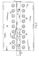
- the burner tube 10 is a stainless steel tube of circular cross-section having one end closed by a cap 12. The opposite end is provided with an annular plug 14 and a supply tube 16 is fixed within the plug and forms an aerator sleeve to receive the jet orifice of a gas tap (not shown).
- the supply tube extends for about one third of the length of the burner tube (this is a typical dimension, although in some constructions it may need to extend for as much as half of its length) and may be generally concentrically arranged therein, if desired with supporting lugs or apertured washers.
- the supply tube is a venturi having a waist 18 for the purpose of improving flow through the aerator and into the burner.
- baffle 20 The end of the supply tube which is located in the burner tube is provided with a baffle 20.
- this is formed of sheet metal folded to substantially V configuration with irs apex 22 nearest to the inlet end 16, and with the free ends 24 of the limbs of the V curved divergently from one another and the extremities of those limbs shaped along their edges 26 so as to conform to the internal cross-section of the burner tube. Said free edges are notched at 28 to permit gas flow through the baffle to reach the portion of the burner tube located on the opposite side of the baffle to the supply tube.
- the divergent limbs act as deflectors to encourage gas flow within the burner tube in the opposite direction to that of glas flow within the supply tube, so as to reach the end of the burner tube adjacent the aerator, and the arros A in Figure 2 indicate this gas flow.
- the burner tube is provided with two rows of jets in the form of regularly spaced apertures 30 located for example 180° apart on the surface of the tube and spaced apart over its whole length, and when the tube is in a particular position the jets are equi-spaced about a vertical plane.
- Additional jet apertures 32 are provided, at 180° spacing and symmetrically arranged with the respect to the main jet apertures, and these additional apertures open into a narrow space defined between the exterior of the burner tube and a sheet metal deflector 34 fixed to the burner tube.
- the deflector is of arcuate cross-section and extends about the burner tube periphery to a position approaching the main jets, and the result is that gas led through the subsidiary jets emerges along the edge of the deflector to provide a continuous ribbon like flame which, for example, ensures that all of the main flames provided by the main jets become ignited when any one of them is ignited.
- the deflector may likewise be made of stainless steel and can be for example spot-welded to the burner tube.
- the burner tube is supported below and generally parallel to a structure comprising a sheet metal hot plate 36 and a generally parallel sheet of wire mesh, expanded metal or the like 38 to act as'a heat dissipator, the two being connected together at a plurality of points, and the burner tube being connected to these for example by a series of posts 40 secured to the burner tube and to the plates.
- a series of posts 40 secured to the burner tube and to the plates.
Landscapes
- Engineering & Computer Science (AREA)
- Chemical & Material Sciences (AREA)
- Combustion & Propulsion (AREA)
- Mechanical Engineering (AREA)
- General Engineering & Computer Science (AREA)
- Gas Burners (AREA)
- Pre-Mixing And Non-Premixing Gas Burner (AREA)
Applications Claiming Priority (2)
| Application Number | Priority Date | Filing Date | Title |
|---|---|---|---|
| GB8100090 | 1981-01-02 | ||
| GB8100090 | 1981-01-02 |
Publications (2)
| Publication Number | Publication Date |
|---|---|
| EP0055911A2 true EP0055911A2 (fr) | 1982-07-14 |
| EP0055911A3 EP0055911A3 (fr) | 1982-12-15 |
Family
ID=10518776
Family Applications (1)
| Application Number | Title | Priority Date | Filing Date |
|---|---|---|---|
| EP81305987A Withdrawn EP0055911A3 (fr) | 1981-01-02 | 1981-12-21 | Brûleurs à gaz |
Country Status (1)
| Country | Link |
|---|---|
| EP (1) | EP0055911A3 (fr) |
Cited By (4)
| Publication number | Priority date | Publication date | Assignee | Title |
|---|---|---|---|---|
| WO2002028974A3 (fr) * | 2000-10-04 | 2002-08-22 | Du Pont | Copolymeres d'ethylene a faible teneur en acide pour ameliorer l'adherence de pebd a une feuille d'aluminium dans le revetement par extrusion |
| WO2007003484A3 (fr) * | 2005-06-30 | 2008-01-10 | Castfutura Spa | Bruleur de four ou de grill |
| EP1985921A3 (fr) * | 2007-04-27 | 2008-11-12 | Paloma Industries, Ltd. | Brûleur |
| EP2333418A1 (fr) * | 2009-12-14 | 2011-06-15 | Miele & Cie. KG | Four et dispositif de brûleur à gaz, notamment pour un four |
Family Cites Families (3)
| Publication number | Priority date | Publication date | Assignee | Title |
|---|---|---|---|---|
| FR1421600A (fr) * | 1964-11-06 | 1965-12-17 | Sourdillon Ets | Perfectionnements apportés aux appareils à gaz du genre des fourneaux, cuisinières, machines à laver, et autres |
| BE709591A (fr) * | 1968-01-18 | 1968-05-30 | ||
| US4112912A (en) * | 1976-06-16 | 1978-09-12 | Ballentine Earle W | Gas broiler |
-
1981
- 1981-12-21 EP EP81305987A patent/EP0055911A3/fr not_active Withdrawn
Cited By (5)
| Publication number | Priority date | Publication date | Assignee | Title |
|---|---|---|---|---|
| WO2002028974A3 (fr) * | 2000-10-04 | 2002-08-22 | Du Pont | Copolymeres d'ethylene a faible teneur en acide pour ameliorer l'adherence de pebd a une feuille d'aluminium dans le revetement par extrusion |
| WO2007003484A3 (fr) * | 2005-06-30 | 2008-01-10 | Castfutura Spa | Bruleur de four ou de grill |
| EP1985921A3 (fr) * | 2007-04-27 | 2008-11-12 | Paloma Industries, Ltd. | Brûleur |
| US8282391B2 (en) | 2007-04-27 | 2012-10-09 | Paloma Industries, Limited | Burner |
| EP2333418A1 (fr) * | 2009-12-14 | 2011-06-15 | Miele & Cie. KG | Four et dispositif de brûleur à gaz, notamment pour un four |
Also Published As
| Publication number | Publication date |
|---|---|
| EP0055911A3 (fr) | 1982-12-15 |
Similar Documents
| Publication | Publication Date | Title |
|---|---|---|
| US10995965B2 (en) | Ultra-low NOx burner | |
| EP2310742B1 (fr) | Brûleur à tourbillon pour table de cuisson | |
| AU2010216137B2 (en) | Gas burner | |
| US3245458A (en) | Radiant gas burner | |
| US3386431A (en) | Burner construction and method and apparatus for making the same and the like | |
| EP0695911B1 (fr) | Brûleur à gaz avec un diffuseur amélioré | |
| DE69606189T2 (de) | Gasgerät zum erhitzen von flüssigkeiten | |
| US3437415A (en) | Radiant gas burner | |
| EP0797048B1 (fr) | Brûleur à gaz pour appareil de cuisine | |
| US3780954A (en) | Burner construction | |
| ES2197185T3 (es) | Camara de mezcla de quemador. | |
| US3270967A (en) | Gas burners | |
| DE3147993C2 (de) | Metall-Glühofen | |
| US4643670A (en) | Burner | |
| EP0055911A2 (fr) | Brûleurs à gaz | |
| US6485294B2 (en) | NOx reduction device | |
| US4237858A (en) | Thin and flat flame burner | |
| US3871356A (en) | Gas range grate | |
| US5133657A (en) | High turndown sheet metal atmospheric gas burner | |
| US2037400A (en) | Gas burner | |
| US1256243A (en) | Burner. | |
| US1532612A (en) | Gas burner | |
| US3511589A (en) | Gas burner | |
| US1900217A (en) | Gas burner | |
| DE4033503C2 (fr) |
Legal Events
| Date | Code | Title | Description |
|---|---|---|---|
| PUAI | Public reference made under article 153(3) epc to a published international application that has entered the european phase |
Free format text: ORIGINAL CODE: 0009012 |
|
| AK | Designated contracting states |
Designated state(s): AT BE CH DE FR GB IT LU NL SE |
|
| PUAL | Search report despatched |
Free format text: ORIGINAL CODE: 0009013 |
|
| AK | Designated contracting states |
Designated state(s): AT BE CH DE FR GB IT LI LU NL SE |
|
| 17P | Request for examination filed |
Effective date: 19830414 |
|
| STAA | Information on the status of an ep patent application or granted ep patent |
Free format text: STATUS: THE APPLICATION IS DEEMED TO BE WITHDRAWN |
|
| 18D | Application deemed to be withdrawn |
Effective date: 19840416 |
|
| RIN1 | Information on inventor provided before grant (corrected) |
Inventor name: WALKER, STEPHEN JAMES |