EP0055977B1 - Tragbares Instrument zum Messen der Dämpfung einer Fernsprechteilnehmerleitung - Google Patents
Tragbares Instrument zum Messen der Dämpfung einer Fernsprechteilnehmerleitung Download PDFInfo
- Publication number
- EP0055977B1 EP0055977B1 EP81830252A EP81830252A EP0055977B1 EP 0055977 B1 EP0055977 B1 EP 0055977B1 EP 81830252 A EP81830252 A EP 81830252A EP 81830252 A EP81830252 A EP 81830252A EP 0055977 B1 EP0055977 B1 EP 0055977B1
- Authority
- EP
- European Patent Office
- Prior art keywords
- telephone line
- telephone
- reference signal
- measuring device
- portable instrument
- Prior art date
- Legal status (The legal status is an assumption and is not a legal conclusion. Google has not performed a legal analysis and makes no representation as to the accuracy of the status listed.)
- Expired
Links
- 239000003990 capacitor Substances 0.000 claims description 7
- 230000004913 activation Effects 0.000 claims 2
- 230000001419 dependent effect Effects 0.000 claims 1
- 238000005259 measurement Methods 0.000 description 12
- 238000012360 testing method Methods 0.000 description 10
- 238000004891 communication Methods 0.000 description 2
- 238000012423 maintenance Methods 0.000 description 2
- 230000005540 biological transmission Effects 0.000 description 1
- 238000010586 diagram Methods 0.000 description 1
- 238000002955 isolation Methods 0.000 description 1
- 238000012886 linear function Methods 0.000 description 1
- 239000004973 liquid crystal related substance Substances 0.000 description 1
- 230000007257 malfunction Effects 0.000 description 1
- 238000000034 method Methods 0.000 description 1
- 239000013589 supplement Substances 0.000 description 1
- 238000010998 test method Methods 0.000 description 1
Images

Classifications
-
- H—ELECTRICITY
- H04—ELECTRIC COMMUNICATION TECHNIQUE
- H04M—TELEPHONIC COMMUNICATION
- H04M3/00—Automatic or semi-automatic exchanges
- H04M3/22—Arrangements for supervision, monitoring or testing
- H04M3/26—Arrangements for supervision, monitoring or testing with means for applying test signals or for measuring
- H04M3/28—Automatic routine testing ; Fault testing; Installation testing; Test methods, test equipment or test arrangements therefor
- H04M3/30—Automatic routine testing ; Fault testing; Installation testing; Test methods, test equipment or test arrangements therefor for subscriber's lines, for the local loop
- H04M3/308—Craftsperson test terminals
Definitions
- the present invention refers to a portable instrument for measuring the attenuation of a subscriber's telephone line as set out in the precharacterising part of claim 1.
- the invention refers to an instrument which allows the measurement of attenuation on users linbs and at the same time allowing that the telephone necessary for the calls and service conversation automatically stays connected to the line when the measurement is not being carried out and is excluded during the measurements guaranteeing nevertheless the d.c. current flow in the line.
- the ratio between the level of the signal transmitted and the level of the signal received represents the attenuation of the telephone line.
- a calibrated generator is permanently installed to which automatic connection is possible. The measurement can therefore be carried out by dialing a given numerical, which corresponds to the generator in the exchange, thus disconnecting the telephone apparatus from the plug and inserting instead the instrument for measuring the received level (normally a selective voltmeter).
- a resistor R, of 150 ohm is connected in series with an inductance L, constituting a negligible ohmic resistance for d.c. current and constituting a very high impedance for signals at acoustic frequencies utilised for the measurement.
- Capacitors C, and C 2 even though not allowing d.c. current flow constitute a negligible impedance for a signal at acoustic frequencies which can be closed by a resistor R 2 of 600 ohm-equal to the characteristic impedance of the line.
- connection can be held up if the telephone is disconnected and the test jack is connected later, even if this time is in the order of milliseconds.
- the parallel connection of the telephone and the test equipment will lead to misadaptions of line impedance although adaption of input impedance is intended.
- the instrument for measuring telephone line attenuations should not be heavy and cumbersome and should require for its use the intervention of unskilled workers only.
- a further aim of the invention is that of realizing an instrument which can be used in pairs by two operators for measuring the attenuation from the plug of one subscriber to the plug of another subscriber thus including in the attenuation measurement not onlythe subscribers lines but all the automatic switching and transmission equipments.
- a further aim of the invention is that of realising an instrument for measuring the attenuation of the users line in which a particular circuital disposition consents that the telephone set necessary for the call and service conversation remains automatically connected to the line when the measurement is not being carried out.
- the telephone set is automatically excluded, guaranteeing however the flow of the line's d.c. current.
- a resistor and an inductance are connected in series so that DC current may flow from one terminal of the telephone line to the other terminal thereof.
- this circuit avoids the risk of a DC short circuit between these terminals.
- the impedance characteristic of a normal telephone can be simulated. This is an important aspect of the invention because at measuring a true line attenuation the line should be closed by exactly the same electrical characteristic as under normal conditions. Provision of three push-button switches, instead of a combination of a rotary switch and a test jack to be connected, ensures that DC connections can be maintained and not be interrupted erroneously.
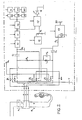
- FIG. 1 the users socket.
- B is represented the connecting plug which with the pins A, A is connected to the socket A 1 , with clips T, T is connected to the service telephone and with the contacts C, C, C is connected to the connecting lead to the measuring apparatus which is included in the dashed insert.
- V indicates the supply battery
- C 1 , C 2 and C 3 are capacitors
- R 1 and R 3 are resistances
- L is an inductance
- block 10 represents an acoustic frequency amplifier
- 11 represents a rectifier
- 12 an analogue to digital converter
- 13A and 13 8 are represented three blocks of PROM memory each of which respectively commands one of the displays 14, 14A and 14 B .
- Pressing button P z which sends the signal onto the line, the service telephone is disconnected, the instrument circuits are fed and the signal from the oscillator is sent to the telephone line by means of the capacitor C 2 , of high value (e.g. 40 pF) and therefore such as to present a negligible impedance to the frequency of 800 Hz.
- the capacitor C 2 of high value (e.g. 40 pF) and therefore such as to present a negligible impedance to the frequency of 800 Hz.
- a second operator placed at the other end of the line in possession of a second instrument, can measure the signal received by pressing button P 1 , which in addition to allowing the supply of the instruments circuits, disconnects the telephone set and connects to the line instead the circuits for measuring the received level, by means of the capacitor C 1 , also a high value (40 ⁇ F).
- the 800 Hz signal coming from the line locks onto the resistance R 1 (600 ohm) placed at the input of the measuring circuits.
- the inductor L, and the capacitor C 3 constitute a parallel resonant circuit and therefore the very high impedance at the head of this circuit in correspondence of the resonance frequency (800 Hz) is such that no current at this frequency circulates across R 3 .
- the circuits for measuring the received level are constituted by an amplifier followed by a rectifier.
- a d.c. voltage is present of value proportional to the amplitude of the 800 Hz signal present at the input of the amplifier.
- This d.c. voltage is sent to an 8 bit analogue to digital converter.
- the 8 bit words obtained in this way represent the addresses of three PROM which have the purpose of converting the linear function of the input signal into a logarithm function, in such a way as to obtain, on a diode LED or liquid crystal display, a measure of the signal level at 800 Hz expressed in dBm.
- the first two figures indicate respectively the tens and units, while the third figure indicates tenths of dBm.
- the instrument In addition to giving the value of the received signal on a display, the instrument also gives a pilot light indication, in the case when the received signal is greater than the acceptable minimum. This is carried out by means of a voltage comparator which compares the voltage at the output of the rectifier with a reference voltage derived from the battery by means of a voltage regulator and causes the "switching-on" of a luminous diode.
- a voltage comparator which compares the voltage at the output of the rectifier with a reference voltage derived from the battery by means of a voltage regulator and causes the "switching-on" of a luminous diode.
- the program stored in the PROM causes the visualising of this condition on the display (in case of a very low level for example "L.L.” can appear, while in the case of a very high level “H.L.” can appear.
Landscapes
- Engineering & Computer Science (AREA)
- Signal Processing (AREA)
- Monitoring And Testing Of Exchanges (AREA)
Claims (6)
Applications Claiming Priority (2)
| Application Number | Priority Date | Filing Date | Title |
|---|---|---|---|
| IT47520/81A IT1142211B (it) | 1981-01-06 | 1981-01-06 | Dispositivo portatile per la misura dell'attenuazione della linea telefonica dell'abbonato |
| IT4752081 | 1981-01-06 |
Publications (2)
| Publication Number | Publication Date |
|---|---|
| EP0055977A1 EP0055977A1 (de) | 1982-07-14 |
| EP0055977B1 true EP0055977B1 (de) | 1987-03-25 |
Family
ID=11260842
Family Applications (1)
| Application Number | Title | Priority Date | Filing Date |
|---|---|---|---|
| EP81830252A Expired EP0055977B1 (de) | 1981-01-06 | 1981-12-22 | Tragbares Instrument zum Messen der Dämpfung einer Fernsprechteilnehmerleitung |
Country Status (4)
| Country | Link |
|---|---|
| US (1) | US4413163A (de) |
| EP (1) | EP0055977B1 (de) |
| DE (1) | DE3176051D1 (de) |
| IT (1) | IT1142211B (de) |
Families Citing this family (10)
| Publication number | Priority date | Publication date | Assignee | Title |
|---|---|---|---|---|
| US4513176A (en) * | 1983-02-28 | 1985-04-23 | Fostveit Edgar H | Test apparatus for telephone equipment |
| US4588862A (en) * | 1984-01-16 | 1986-05-13 | Grabowy James G | Visual display network interface |
| US4760592A (en) * | 1985-02-07 | 1988-07-26 | Secom General Corporation | Wire tap detection device with passive testing |
| GB2173974B (en) * | 1985-04-18 | 1988-09-07 | Stc Plc | Method of testing telephone subscribers lines |
| US4679224A (en) * | 1985-12-02 | 1987-07-07 | Keptel, Inc. | Telephone line testing circuit |
| US4680783A (en) * | 1985-12-16 | 1987-07-14 | Gte Communication Systems, Inc. | Telephone security violation detection device |
| US4756017A (en) * | 1987-03-23 | 1988-07-05 | Golden State Communications Service, Inc. | Telephone test device |
| US5073919A (en) * | 1990-10-10 | 1991-12-17 | Teradyne, Inc. | Automatically testing telephone lines |
| US5594347A (en) * | 1995-05-22 | 1997-01-14 | Adc Telecommunications, Inc. | Non-invasive testing of video signals with a jack module and amplification circuit |
| US20060223380A1 (en) * | 2005-04-05 | 2006-10-05 | Dell Products L.P. | Device for testing connectivity of a connector including spring contact pins |
Family Cites Families (4)
| Publication number | Priority date | Publication date | Assignee | Title |
|---|---|---|---|---|
| US3598929A (en) * | 1967-12-14 | 1971-08-10 | Hickok Electrical Instr Co The | Electroacoustic transmission testing device |
| US4025736A (en) * | 1974-09-12 | 1977-05-24 | Rfl Industries, Inc. | Apparatus for measuring the value of a variable condition |
| DE2814097A1 (de) * | 1978-04-01 | 1979-10-04 | Wolfgang Zaeh | Sprechstellenpruefgeraet |
| US4323738A (en) * | 1980-04-10 | 1982-04-06 | Oros Corporation | Portable telephone line test set |
-
1981
- 1981-01-06 IT IT47520/81A patent/IT1142211B/it active
- 1981-12-22 DE DE8181830252T patent/DE3176051D1/de not_active Expired
- 1981-12-22 EP EP81830252A patent/EP0055977B1/de not_active Expired
- 1981-12-23 US US06/334,066 patent/US4413163A/en not_active Expired - Fee Related
Also Published As
| Publication number | Publication date |
|---|---|
| IT1142211B (it) | 1986-10-08 |
| DE3176051D1 (en) | 1987-04-30 |
| EP0055977A1 (de) | 1982-07-14 |
| IT8147520A0 (it) | 1981-01-06 |
| US4413163A (en) | 1983-11-01 |
Similar Documents
| Publication | Publication Date | Title |
|---|---|---|
| US5402073A (en) | Near-end communications line characteristic measuring system with a voltage sensitive non-linear device disposed at the far end | |
| US4912755A (en) | Line current test device | |
| US6212258B1 (en) | Device for remotely testing a twisted pair transmission line | |
| US5218616A (en) | Telephone line tester | |
| EP0055977B1 (de) | Tragbares Instrument zum Messen der Dämpfung einer Fernsprechteilnehmerleitung | |
| CA1140283A (en) | Test set | |
| CA1311067C (en) | Customer line tester | |
| US4163937A (en) | Multi-function test apparatus to test, selectively and as desired, electrical circuits, circuit components and transistors | |
| CA1292585C (en) | Ground start circuit | |
| US4922531A (en) | Line interface circuit | |
| US3941950A (en) | Telephone line testing instrument having a supervising capability | |
| US4862491A (en) | Remote disconnection and short-circuiting apparatus and method | |
| US4679224A (en) | Telephone line testing circuit | |
| US4581494A (en) | Telephone interface-test device | |
| US6301227B1 (en) | Systems and methods for allowing transmission systems to effectively respond to automated test procedures | |
| US5115462A (en) | Remotely controlled apparatus for conditioning telephone line exclusive of metallic DC bypass pair | |
| US4369341A (en) | Customer line test termination device | |
| USRE29499E (en) | On premise telephone loop tester | |
| US7010096B1 (en) | Remote testing of a communications line | |
| US6169784B1 (en) | Telecommunication line termination test | |
| CA2446629A1 (en) | Automated subscriber loop identification and data transfer for subscriber loop testing | |
| US5778050A (en) | Portable line test telephone | |
| US4445007A (en) | Remote testing of subscriber line interface circuits | |
| US3526729A (en) | Transmission measuring system with harmonic generating means | |
| KR200453993Y1 (ko) | 휴대용 선로 시험기 |
Legal Events
| Date | Code | Title | Description |
|---|---|---|---|
| PUAI | Public reference made under article 153(3) epc to a published international application that has entered the european phase |
Free format text: ORIGINAL CODE: 0009012 |
|
| AK | Designated contracting states |
Designated state(s): DE FR GB NL SE |
|
| 17P | Request for examination filed |
Effective date: 19830221 |
|
| R17P | Request for examination filed (corrected) |
Effective date: 19830114 |
|
| GRAA | (expected) grant |
Free format text: ORIGINAL CODE: 0009210 |
|
| AK | Designated contracting states |
Kind code of ref document: B1 Designated state(s): DE FR GB NL SE |
|
| REF | Corresponds to: |
Ref document number: 3176051 Country of ref document: DE Date of ref document: 19870430 |
|
| ET | Fr: translation filed | ||
| PGFP | Annual fee paid to national office [announced via postgrant information from national office to epo] |
Ref country code: NL Payment date: 19871231 Year of fee payment: 7 |
|
| PLBE | No opposition filed within time limit |
Free format text: ORIGINAL CODE: 0009261 |
|
| STAA | Information on the status of an ep patent application or granted ep patent |
Free format text: STATUS: NO OPPOSITION FILED WITHIN TIME LIMIT |
|
| 26N | No opposition filed | ||
| PG25 | Lapsed in a contracting state [announced via postgrant information from national office to epo] |
Ref country code: DE Effective date: 19880901 |
|
| PG25 | Lapsed in a contracting state [announced via postgrant information from national office to epo] |
Ref country code: GB Effective date: 19881222 |
|
| PG25 | Lapsed in a contracting state [announced via postgrant information from national office to epo] |
Ref country code: NL Effective date: 19890701 |
|
| NLV4 | Nl: lapsed or anulled due to non-payment of the annual fee | ||
| GBPC | Gb: european patent ceased through non-payment of renewal fee | ||
| PG25 | Lapsed in a contracting state [announced via postgrant information from national office to epo] |
Ref country code: FR Free format text: LAPSE BECAUSE OF NON-PAYMENT OF DUE FEES Effective date: 19890831 |
|
| REG | Reference to a national code |
Ref country code: FR Ref legal event code: ST |
|
| PG25 | Lapsed in a contracting state [announced via postgrant information from national office to epo] |
Ref country code: SE Effective date: 19891223 |
|
| EUG | Se: european patent has lapsed |
Ref document number: 81830252.3 Effective date: 19900104 |