EP0055978A2 - Chariot - Google Patents
Chariot Download PDFInfo
- Publication number
- EP0055978A2 EP0055978A2 EP81850190A EP81850190A EP0055978A2 EP 0055978 A2 EP0055978 A2 EP 0055978A2 EP 81850190 A EP81850190 A EP 81850190A EP 81850190 A EP81850190 A EP 81850190A EP 0055978 A2 EP0055978 A2 EP 0055978A2
- Authority
- EP
- European Patent Office
- Prior art keywords
- wheels
- support wheel
- truck
- wheel
- cylinder
- Prior art date
- Legal status (The legal status is an assumption and is not a legal conclusion. Google has not performed a legal analysis and makes no representation as to the accuracy of the status listed.)
- Withdrawn
Links
Images


Classifications
-
- B—PERFORMING OPERATIONS; TRANSPORTING
- B66—HOISTING; LIFTING; HAULING
- B66F—HOISTING, LIFTING, HAULING OR PUSHING, NOT OTHERWISE PROVIDED FOR, e.g. DEVICES WHICH APPLY A LIFTING OR PUSHING FORCE DIRECTLY TO THE SURFACE OF A LOAD
- B66F9/00—Devices for lifting or lowering bulky or heavy goods for loading or unloading purposes
- B66F9/06—Devices for lifting or lowering bulky or heavy goods for loading or unloading purposes movable, with their loads, on wheels or the like, e.g. fork-lift trucks
- B66F9/075—Constructional features or details
- B66F9/07559—Stabilizing means
-
- B—PERFORMING OPERATIONS; TRANSPORTING
- B66—HOISTING; LIFTING; HAULING
- B66F—HOISTING, LIFTING, HAULING OR PUSHING, NOT OTHERWISE PROVIDED FOR, e.g. DEVICES WHICH APPLY A LIFTING OR PUSHING FORCE DIRECTLY TO THE SURFACE OF A LOAD
- B66F9/00—Devices for lifting or lowering bulky or heavy goods for loading or unloading purposes
- B66F9/06—Devices for lifting or lowering bulky or heavy goods for loading or unloading purposes movable, with their loads, on wheels or the like, e.g. fork-lift trucks
- B66F9/075—Constructional features or details
- B66F9/07586—Suspension or mounting of wheels on chassis
-
- B—PERFORMING OPERATIONS; TRANSPORTING
- B60—VEHICLES IN GENERAL
- B60G—VEHICLE SUSPENSION ARRANGEMENTS
- B60G2300/00—Indexing codes relating to the type of vehicle
- B60G2300/02—Trucks; Load vehicles
- B60G2300/022—Fork lift trucks, Clark
Definitions
- the present invention relates to a truck and in particular to a kind of fork-lift truck which exhibits lifting devices intended for the lifting of loads. Adjacent to said lifting devices are normally situated pairs of wheels located at a certain distance from each other intended to withstand a force corresponding to the weight of the load and that part of the service weight of the truck which is distributed onto said front pairs of wheels. Also present are pairs of wheels, usually steerable, by means of which the truck may be manoeuvered.
- pairs of wheels may, of course, be regarded as undesirable to designate the pairs of wheels as the front pair of wheels and the rear pair of wheels, since the truck must be capable of being driven in both directions, in spite of which the following specification will use the expression front pair of wheels in respect of the pair of wheels which will support the load and which are driven, whilst the expression rear pair of wheels will be used in respect of the pairs of wheels which will steer the truck.
- the principle of invention may also be applied to articulated fork-lift trucks.
- front pairs of wheels are dimensioned to support not only that part of the service weight of the truck which is distributed onto the front axle but also the load which can be lifted and transported by the lifting devices.
- the torsional moment about the front axle must be selected such that the torsional moment due to gravity and to the position of the centre of gravity of the truck and the distance to the front axle is greater than the torsional moment due to gravity and to the position of the centre of gravity of the load and the 'distance to the front axle or, more correctly, the front support point of the truck.
- the present invention relates to a truck of the.nature described above, said truck having succeeded,in solving the aforementioned problems.
- the invention proposes the installation between the pairs of front wheels of a support wheel designed so as to be capable of absorbing a proportion of the compressive forces normally acting on the pairs of front wheels.
- the support wheel is also arranged so as to be capable of being forced down onto the base by means of a device consisting of a hydraulic piston and cylinder, and with the pressure in said device being controlled by the pressure supplied to a load-lifting hydraulic piston and cylinder device. This causes the direct transfer of the compressive force to the support wheel, said force increasing in proportion to the weight of the load.
- connection of an accumulator into the hydraulic system produces the advantage that said accumulator will absorb any momentary variations in pressure resulting from movements of the hydraulic piston in the support wheel cylinder, i.e. the support wheel will be caused to follow an uneven base at the same time maintaining the degree to which the compressive forces are removed from the wheels.
- the invention also proposes the possibility of causing the support wheel to be free to pivot in relation to the position of a steering wheel, for which purpose the support wheel must be introduced into a holder which is not only free to pivot about a vertical shaft but is also capable of being raised and lowered along a horizontal shaft located at a certain distance.
- the present invention also proposes a design in which the load-carrying capacity of the truck can be increased without the need for major design changes by positioning the support wheel between the front pair of wheels and the centre of gravity of the load thereby reducing the torsional moment generated by the load.
- This arrangement enables the force on the front pair of wheels and its axle loading to be transferred to a different point on the base, this being a point closer to the centre of gravity of the load.
- a truck designed for a certain load may be used for-greater loads since the torsional moment produced by the load is.less.
- Fig. 1 shows a greatly simplified side view of a truck 1 fitted with a steering wheel 2 which, when turned, will cause rear wheels 3 to turn which are arranged in pairs and are attached to a frame assembly 4 of which the front part supports more heavily dimensioned pairs of front wheels 5 with a greater load-carrying capacity.
- the pairs of front wheels 5 are dimensioned so as to be capable of absorbing compressive forces corresponding to that part of the service weight of the truck which is distributed onto the pairs of front wheels and a maximum load 'L' placed on the lifting devices 7 .
- the front part of the truck 1 is fitted with'vertically extending parallel masts 6 and 6' , along which the lifting devices 7 are free to move.
- the lifting devices 7 have on the one hand a sliding surface facing the mast and on the other hand an organ 7a which operates in conjunction with an organ inside the masts. Movement of the lifting device 7 along the mast 6 takes place with the help of a device not shown in Fig. 1 consisting of a hydraulic piston and cylinder operating in conjunction with the organ.
- the pairs of front wheels 5 are at least two in number, of course, and are located at a certain distance from each other. It is not unusual, however, to have double pairs of front wheels, which means that the front wheels are four in number and are arranged in pairs located at a certain distance from each other. As far as the rear wheels 3 are concerned, these are normally located at a certain distance from each other and are two in number.
- the present invention relates to the possibility of arranging a. support wheel 8 between the pairs of-front wheels 5 , said support wheel having to be capable of absorbing a proportion of the compressive force P acting on the pair of front wheels 5 , partly due to the load 7 , and applied to the base 9.
- the support wheel 8 is located between the front wheels 5 and the load 'L'.
- the load-carrying capacity of a truck is normally limited by the fact that the torsional moment T x a must be greater than the torsional moment of the maximum load L x b , although the torsional moment L x b is reduced considerably by the present invention, at the same time as the axle loading is distributed to other points on the base.
- the support wheel 8 which is shown in Fig. 2 to consist of two support wheels 8a and 8b located adjacent to each other and free to rotate about the same axle, is attached by means of a support wheel axle and a holder 8d to a plate 10 , which is held in channels 11, 11a in such a way that the plate 10 may be caused to move up and down.
- This up and down movement is produced by a device 12 consisting of a hydraulic piston and cylinder with connections 13 .
- This arrangement makes it possible, via a distributor 12' positioned next to the driver, for hydraulic pressure to be applied to the cylinder device 12 , thereby causing the plate 10 with its attached wheels 8 to be forced against the base 9 with a force P1 , thereby causing the compressive force P from the pair of wheels 5 to be reduced to a corresponding degree.
- the distributor 12' enables the compressive force 'P1' acting on the base 9 and generated by the hydraulic piston and cylinder device to be controlled.
- the wheel 8 should be capable of being raised out of contact with the base 9 , especially when the truck is turning, since any tight turn by the truck would cause the wheel 8 to move sideways, resulting in a high level of wear.
- the present invention proposes an additional embodiment in which the wheel 8 is attached by means of a common axle 8c to a holder 8d in such a way that it is free to rotate.
- the holder 8d operates in conjunction with a piston-rod 12a , of which the piston 12b is mounted in a cylinder 12c .
- hydraulic pressure applied via the pipework 13 to the piston 12 will cause a compressive force T1 to be applied to the base 9 .
- the support wheel 8 may also be fitted with a control device which will respond to any deflection of the steering wheels 3 and 3' .
- the support wheel is angled in the horizontal plane to follow the steering geometry of the truck. Even when this device is fitted, it may be desirable to be able to control the piston 12b so that the wheel 8 is not forced against the base 9 .
- FIG. 4 An example of a conceivable control arrangement of this kind is illustrated in Fig. 4 , in which a holder 8d is so arranged as to be free to pivot about a central axle 12a' for the piston-rod 12 located by means of a bearing device 14a between the holder 8d and a support 14 .
- the support 14 operates in conjunction with parallel arms 15, 15a attached to the-frame assembly or chassis 4 by means of a pivoting axle 15' and 15a' in such a way as to be free to pivot.
- the wheel 8 can be caused to move up and down, as shown in Fig. 3, which means that the wheel will adapt to and follow any unevenness in the base 9 .
- Fig. 4 shows the manner in which the pairs of front wheels 5 and 5' and the pairs of rear wheels 3 and 3' are located in relation to each other, and with the help of the steering wheel 2 a segment 15b is caused to rotate about a pivoting axle 16 .
- Rotation of the segment 15b will cause the pair of wheels 3 and 3' to turn, although the rotation is also linked via an arm 19 to the holder 8d for the wheel 8.
- the support wheel 8 With the help of the arm 19 the support wheel 8 will be caused to rotate about the axle 12a' in relation to the turning of the wheels 3 , which means that the aforementioned wear will be eliminated.
- a second embodiment has the wheel 8 operating via a piston device, so that the wheel 8 is able to follow any unevenness in the base causing a control arrangement to act on the piston-rod or to cause it to extend. Any deflection of the control arrangement will take place in relation to the deflection of the steering wheels and the steering geometry of the truck.
- the reference designation 20 is used to indicate a micro-switch, which may be connected to the distributor or operating lever 12' in such a way that, when the pair of wheels 3,3' turns, the effect of the hydraulic piston and cylinder arrangement will cease, and that, as soon as the pairs of wheels 3,3' adopt the position shown in Fig. 4, the hydraulic, piston and cylinder arrangement will cause the support wheel 8 to be forced against the base 9 .
- the present-invention proposes that the pipework 13 be connected to an accumulator 21 , said pipework 13 operating via pipework 13a in conjunction with a cylinder 22 intended to raise and lower the lifting device 7 .
- the cylinders 22 are positioned inside or between the masts 6, 6'.
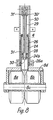
- FIG. 6 it is shown an alternative embodiment of the attachment of the support wheel in the frame 4.
- Support wheels 8a, 8b are turnable arranged to a shaft 8c, which is attached to a holder 8d.
- the upper central portion of the holder 8a cooperates partly with a guiding tube 23 (shown as a sectionalled cut) partly with a bottom portion 24a of a hydraulic cylinder 24.
- the bottom portion 23a of the guiding tube 23 and the bottom portion 24a of the hydraulic cylinder 24 are rigidly attached to the holder 8d.
- the holder 8d may be turned around a central axis 25, which also is the central axis for the piston rod 29, by the fact that the tube 23 has a bearing at 26 for rotation and axial movement.
- the holder 8d may be turned by only in Figure 7 shown hydraulic piston and cylinder arrangement 27.
- the holder 8d may be raised or lowered (in the figures the holder 8d is shown in its uppermost position). This is caused by the fact that the bottom portion of the hydraulic cylinder 24 is attached to the holder 8d and the hydraulic piston 28 is fixed.
- the upper portion of the _ piston rod is fixed to the frame of the truck. Hydraulic pressure acting on the under surface of the piston 28 presses the hydraulic cylinder 24 downwards and a pressure acting on the upper surface of the piston 28 presses the hydraulic cylinder upwards.
- Ducts 30' and 31' having orifices 30 and 31 are arranged within the piston rod and terminate at not shown connection portions in the upper portion 29b of the rod 29. The fixed attachment of the upper poriton 29b for the piston rod 29 is not shown.
- FIG. 7 it is shown a hydraulic circuit for the steering function.
- One previously known control valve 33 is arranged for controlling the hydraulic pressure and the flow through the conduits 34 and 35 to a hydraulic piston and cylinder device 36, where the piston rod 37 actuates one in the steering mechanism included steering arm 3 8 attached to the steering wheels.
- the arm 38 cooperates with a first hydraulic piston and cylinder device 39, which via conduits 40, 41 is connected to a second hydraulic piston and cylinder device 27.
- the devices 39 and 27 may preferably be identical.
- the hydraulic piston and cylinder device 27 is connected at 42 to the frame 4 of the truck and at 43 to the edge portion of the holder 8d, for causing a turning motion of the support wheels. 8a, 8b around the axis 25.
- a displacement of the piston in the device 39 causes a corresponding displacement of the piston in the device 27, thus causing a turning of the support wheels in dependence of the setting of the steering wheel 3.
- FIG. 8 it is shown a further embodiment of the device according to Fig. 6.
- the guiding tube 23 is eliminated because the outer surface 24b of the cylinder 24 has a slip fit to the bearing devices 26, 26a, which are attached to the frame 4.
- a tubular device 50 fixed to the frame 4, shall support the bearing device 26, 26a.
- the remaining parts in Figure 8 have been given the same reference numerals as in the embodiment according to Figure 6.
- the connecting conduits 30' and 31' have been shown.
- the present invention is not, of course, restricted to the preferred embodiment indicated above by way of an example, but may undergo modifications within the scope of the following Patent Claims.
Landscapes
- Engineering & Computer Science (AREA)
- Transportation (AREA)
- Structural Engineering (AREA)
- Civil Engineering (AREA)
- Life Sciences & Earth Sciences (AREA)
- Geology (AREA)
- Mechanical Engineering (AREA)
- Handcart (AREA)
- Vehicle Body Suspensions (AREA)
- Forklifts And Lifting Vehicles (AREA)
Applications Claiming Priority (2)
| Application Number | Priority Date | Filing Date | Title |
|---|---|---|---|
| SE8007462 | 1980-10-23 | ||
| SE8007462A SE423989B (sv) | 1980-10-23 | 1980-10-23 | Truck |
Publications (2)
| Publication Number | Publication Date |
|---|---|
| EP0055978A2 true EP0055978A2 (fr) | 1982-07-14 |
| EP0055978A3 EP0055978A3 (fr) | 1984-12-19 |
Family
ID=20342068
Family Applications (1)
| Application Number | Title | Priority Date | Filing Date |
|---|---|---|---|
| EP81850190A Withdrawn EP0055978A3 (fr) | 1980-10-23 | 1981-10-16 | Chariot |
Country Status (3)
| Country | Link |
|---|---|
| EP (1) | EP0055978A3 (fr) |
| JP (1) | JPS57131698A (fr) |
| SE (2) | SE423989B (fr) |
Cited By (2)
| Publication number | Priority date | Publication date | Assignee | Title |
|---|---|---|---|---|
| WO1995030618A1 (fr) * | 1994-05-09 | 1995-11-16 | Teledyne Industries Inc. | Chariot elevateur a support de fourche |
| CN103754797A (zh) * | 2014-02-08 | 2014-04-30 | 胥传明 | 带路障扶助装置的叉车 |
Family Cites Families (5)
| Publication number | Priority date | Publication date | Assignee | Title |
|---|---|---|---|---|
| US2754020A (en) * | 1954-05-18 | 1956-07-10 | Thomas J Dunn | Fork lift attachment for a work vehicle |
| US3077356A (en) * | 1958-02-03 | 1963-02-12 | Shepherd Machinery Co | Transporter for earth mover |
| US3191963A (en) * | 1964-01-13 | 1965-06-29 | Challenge Cook Bros Inc | Retractable axle for vehicle load distribution |
| SE316722B (fr) * | 1968-06-06 | 1969-10-27 | Lidhults Mekaniska Verkstad Ab | |
| GB1577310A (en) * | 1978-04-05 | 1980-10-22 | Lancer Boss Ltd | Load carrying vehicles |
-
1980
- 1980-10-23 SE SE8007462A patent/SE423989B/sv unknown
-
1981
- 1981-09-29 SE SE8105744A patent/SE438501B/sv not_active IP Right Cessation
- 1981-10-16 EP EP81850190A patent/EP0055978A3/fr not_active Withdrawn
- 1981-10-23 JP JP56170645A patent/JPS57131698A/ja active Pending
Cited By (2)
| Publication number | Priority date | Publication date | Assignee | Title |
|---|---|---|---|---|
| WO1995030618A1 (fr) * | 1994-05-09 | 1995-11-16 | Teledyne Industries Inc. | Chariot elevateur a support de fourche |
| CN103754797A (zh) * | 2014-02-08 | 2014-04-30 | 胥传明 | 带路障扶助装置的叉车 |
Also Published As
| Publication number | Publication date |
|---|---|
| SE423989B (sv) | 1982-06-21 |
| SE438501B (sv) | 1985-04-22 |
| SE8007462L (sv) | 1982-04-24 |
| EP0055978A3 (fr) | 1984-12-19 |
| JPS57131698A (en) | 1982-08-14 |
| SE8105744L (sv) | 1982-04-24 |
Similar Documents
| Publication | Publication Date | Title |
|---|---|---|
| EP1123894B1 (fr) | Chargeur | |
| US5015004A (en) | Elevating, reversible self-steering suspension system | |
| US4424872A (en) | Truck | |
| US5113960A (en) | Lift truck with a drive unit pre-tensioned by spring loading in the vertical direction | |
| US4530515A (en) | Dual stub axle air spring suspension with high-axle hydraulic lift | |
| EP0283500B1 (fr) | Bogie elevateur pour vehicule | |
| US3007590A (en) | Shovel loaders | |
| US3479049A (en) | Axle load distributing and balancing device | |
| US4274795A (en) | Load carrying vehicles | |
| GB2311967A (en) | A variable-track, four wheel steering agricultural vehicle with active suspension | |
| US4046218A (en) | Floating steering axle | |
| CA1272376A (fr) | Suspension perfectionnee pour mecanisme de traction d'un engin de terrassement articule | |
| EP1437324B1 (fr) | Appareil de travail | |
| US2904203A (en) | Lift truck | |
| EP0055978A2 (fr) | Chariot | |
| US3370730A (en) | Articulated vehicle | |
| US3424475A (en) | Lift truck suspension system | |
| EP0919404B1 (fr) | Installation de support de roues pour chariot élévateur | |
| US6264221B1 (en) | Base structure for a mobile access platform | |
| US2187197A (en) | Industrial truck | |
| US3080177A (en) | Levelizing suspension for vehicles | |
| US6439827B1 (en) | Load handling vehicle | |
| US3080175A (en) | Industrial truck and rocking wheel assemblage therefor | |
| JPH08112006A (ja) | 農業用トラクタの作業機連結構造 | |
| US1891399A (en) | Motor vehicle mechanism |
Legal Events
| Date | Code | Title | Description |
|---|---|---|---|
| PUAI | Public reference made under article 153(3) epc to a published international application that has entered the european phase |
Free format text: ORIGINAL CODE: 0009012 |
|
| AK | Designated contracting states |
Designated state(s): AT BE CH DE FR GB IT LU NL |
|
| 17P | Request for examination filed |
Effective date: 19830112 |
|
| PUAL | Search report despatched |
Free format text: ORIGINAL CODE: 0009013 |
|
| AK | Designated contracting states |
Designated state(s): AT BE CH DE FR GB IT LI LU NL |
|
| STAA | Information on the status of an ep patent application or granted ep patent |
Free format text: STATUS: THE APPLICATION IS DEEMED TO BE WITHDRAWN |
|
| 18D | Application deemed to be withdrawn |
Effective date: 19870505 |