EP0056012A2 - Système d'application d'herbicides - Google Patents
Système d'application d'herbicides Download PDFInfo
- Publication number
- EP0056012A2 EP0056012A2 EP82300037A EP82300037A EP0056012A2 EP 0056012 A2 EP0056012 A2 EP 0056012A2 EP 82300037 A EP82300037 A EP 82300037A EP 82300037 A EP82300037 A EP 82300037A EP 0056012 A2 EP0056012 A2 EP 0056012A2
- Authority
- EP
- European Patent Office
- Prior art keywords
- rope
- applicator
- herbicide
- flow passage
- fluid
- Prior art date
- Legal status (The legal status is an assumption and is not a legal conclusion. Google has not performed a legal analysis and makes no representation as to the accuracy of the status listed.)
- Withdrawn
Links
Images


Classifications
-
- A—HUMAN NECESSITIES
- A01—AGRICULTURE; FORESTRY; ANIMAL HUSBANDRY; HUNTING; TRAPPING; FISHING
- A01M—CATCHING, TRAPPING OR SCARING OF ANIMALS; APPARATUS FOR THE DESTRUCTION OF NOXIOUS ANIMALS OR NOXIOUS PLANTS
- A01M21/00—Apparatus for the destruction of unwanted vegetation, e.g. weeds
- A01M21/04—Apparatus for destruction by steam, chemicals, burning, or electricity
- A01M21/043—Apparatus for destruction by steam, chemicals, burning, or electricity by chemicals
Definitions
- This invention relates generally to liquid agent applicator and dispensing apparatus, and in particular, to contact applicators for post-emergence herbicides.
- grasses and weeds are controlled by the application of a herbicide agent.
- a herbicide agent A wide spectrum of post-emergence herbicides, including selective and non-selective agents, are presently available for eliminating unwanted weeds and wild grasses such as Johnson grass, pigweed, cocklebur, sunflower, volunteer corn and shattercane.
- the broadcast use of selective herbicides which act only upon the weeds and grasses has been limited because of the detrimental effect on natural balances, by the harmful effects on wildlife and the surrounding environment.
- Other herbicides which are generally non-toxic and which have only a minimal effect on the environment are presently available which can kill virtually any plant by contact over a relatively small foliage area of the plant.
- Such non-selective herbicides such as mixtures of isopropylamine salt of N- (phosphonomethyl) glycine and emulsifiable organic materials (available from Monsanto Corporation under the trademark 'Roundup), are used extensively to eliminate weeds or grass in cultivated row crops.
- weeds and grass typically grow to a height substantially higher than the cultivated crop.
- One of the earliest methods for applying the non-selective, contact herbicide was to direct a spray onto the weed or grass while attempting to keep the liquid herbicide off of the crop, and by spot spraying, which killed weeds but also killed the surrounding crop.
- wick or wipe applicator which uses a material such as sponge, cloth or rope for swabbing the herbicide agent onto the weeds.
- the most commonly used applicator has been the rope applicator which has a wick portion immersed in a supply of liquid herbicide.
- a grommet seals the rope against the herbicide supply tank.
- the flow of herbicide is obtained by true wicking action, in which the flow rate depends upon the capillary wicking action of the rope wick and by the tightness of the grommet seal, wherein the flow rate can only be adjusted by rotating the herbicide reservoir to higher or lower positions relative to the rope for increasing or decreasing flow. That method is inaccurate, is slow to change or adjust, and is difficult to maintain a desired level of rope wetness.
- the rope wick applicator has been improved by attaching the ends of the ropes to the herbicide tank through threaded compression fittings which can be tightened or loosened to squeeze the rope and thereby restrict the flow.
- this system is also dependent upon the rotation of the chemical tank for increasing and decreasing the herbicide level for control.
- an object of the present invention to provide a contact applicator for dispensing a liquid agent in which the delivery of liquid herbicide to the applicator is completely independent of wicking action.
- a related object of the invention is to provide an applicator for dispensing a liquid herbicide in which the flow rate of herbicide delivered to the applicator is continuously controllable during field operations so that applicator wetness can be adjusted for varying conditions.
- a liquid agent into the core of a fluid permeable applicator through a metering device such as a tube or orifice plate.
- the liquid agent flows through the metering device into the core and then is emitted from the inside of the applicator to its outside surface.
- the metering device is received within the applicator so that the liquid herbicide is introduced at a controllable rate, proportional to head pressure, directly into its core.
- the applicator is a braided rope having a central flow passage core
- the metering device is a tube having a fine diameter bore.
- a compression fitting forms an annular seal in the rope material around the metering tube to prevent fluid flow by capillary action into its core.
- the flow rate through the metering tube is determined in part by the length of the metering tube, which serves effectively as a flow restrictor, with the resistance to fluid flow being a function of its length.
- the flow rate is continuously adjustable by forcing liquid herbicide into the metering tube from an accumulator in which liquid herbicide is pressurized to a desired level by compressed air.
- the pressure level is controlled by delivering compressed air from an auxillary air tank through a regulator valve.
- the regulator valve When used in conjunction with a sight guage, the regulator valve can be manually adjusted to maintain the applicator wetness for a give ⁇ set of operating conditions, for example tractor speed, humidity, weed population and herbicide strength. Accordingly, weeds can be killed with minimum passes through the field but without excessive application and wasteful dripping of herbicide.
- a give ⁇ set of operating conditions for example tractor speed, humidity, weed population and herbicide strength. Accordingly, weeds can be killed with minimum passes through the field but without excessive application and wasteful dripping of herbicide.
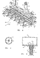
- a rope applicator 10 is supported forwardly of a tractor 12 for applying a liquid herbicide by wiping contact against weeds and grasses growing in a cultivated row crop, for example cotton or soybeans.
- the rope applicator assembly 10 applies herbicide by rubbing or wiping the weed with an absorbent rope 14 that is saturated with the herbicide.
- the herbicide can be either a selective or non-selective systemic agent, with the elevation of the applicator assembly 10 being set above the crop level for non-selective herbicides and below the crop level for selective herbicides.
- the rope applicator assembly 10 includes a left wedge array 10A, a center wedge array 10B, and a right wedge array 10C.
- the left and right wedge arrays 10A, 10C are pivotally mounted on opposite ends of the center array 10B.
- the right array is illustrated in the retracted position for highway travel, and the left array is illustrated in the extended position for field operation.
- the entire rope applicator assembly 10 is supported on a parallel arm linkage 16 which can raise the assembly in elevation from one foot-to four and one-half feet above ground level.
- the operating elevation of the applicator assembly 10 is continuously variable in this range in response to the driving force developed by a hydraulic lift cylinder (not shown).
- the center rope wedge array 10B comprises lower and upper tool bars 18, 20 which are in the form of rigid steel box beams.
- the upper and lower tool bars 18, 20 are sealed at each end, and in addition to providing mechanical support, serve as a compressed air reservoir.
- the upper and lower reservoirs are connected in fluid communication by a tube. 25.
- the lower and upper tool bars are rigidly interconnected by left and right hinge support arms 22, 24.
- the left and right wedge arrays 10A, 10C are pivotally coupled onto the support arms by means of a pivot pin 26.
- the left and right arrays can be extended forwardly for field operation or retracted rearwardly for highway travel, as desired.
- Each array includes multiple rope wedges 14 arranged in an overlapping V-configuration.
- the rope wedges 14 are supported in a linear, horizontal array by an angle beam 28.
- the angle beam 28 is rigidly connected to the lower tool bar 18 by cross plates 30.
- each rope wedge 14 is supported by the angle beam 28 in a horizontal repeating V pattern.
- This V arrangment is maintained by engaging an intermediate portion of each rope applicator with a stand-off bar 32 so that the mid-section of the rope is engaged forwardly of and in spaced relation with the angle beam 28.
- a half- section 14A, 14B of each rope applicator is held in transverse relation with respect to the angle beam 28 on opposite sides of the stand-off bar.
- the legs 14A, 14B of adjacent rope wedges 14 are overlapping as can best be seen in FIGURE 2.
- the overlapping legs of adjacent rope wedges define a converging opening for engaging the grass stalks 34.
- the rope sections 14A, 14B extend transversely with respect to the line of travel as indicated by the arrow 36, the weed plant stalks 34 are contacted in sliding engagement by the rope sections, and each weed surface is exposed to a series of successive positions of contact and wiping engagement with the saturated rope sections 14A, 14B.
- the sliding engagement enhances the desirable wiping action, and extends the duration of wiping action for a given tractor speed.
- the rope segments 14A, 14B are mechanically and hydraulically coupled to a manifold 44 by a coupling sleeve 38 and by a coupling nipple 40.
- the coupling nipple 40 is slightly tapered and extends through an opening 41 in the angle beam 28.
- the coupling nipple -40 is provided with an inlet port fitting 42, which is received in fluid communication with a herbicide distribution manifold 44.
- the inlet port fitting 42 is secured by threaded engagement with the manifold side wall, with the union being sealed with a bonding agent.
- the manifold 44 may comprise a series of tee fittings which are coupled by short, flexible conduit sections.
- the coupling sleeve 38 is forced into telescoping engagement with the tapered nipple 40, and is thereafter sealed with a clamping band 46.
- the rope applicator 14 preferably comprises a length of plastic material, preferably braided, and which can be Nylon, polyester, acrylic, dacron or polypropylene.
- the rope 14 is provided with a central flow passage 48 which extends along its length, in contrast to solid rope applicators of conventional design.
- liquid herbicide is delivered directly into the central flow passage 48 at a controlled flow rate through a flow restrictor assembly 49.
- the flow restrictor assembly 49 comprises a fine bore metering tube 50.
- the discharge end of the metering tube 50 is received within the central flow passage 48, while the inlet end of the metering tube 50 is disposed outside of the central flow passage, and within the bore 52 of the coupling sleeve 38.
- the object of this arrangement is to convey the liquid herbicide from the manifold 44 directly into the central flow passage 48 at a controlled flow rate through the metering tube 50, so that precise control can be exercised on the amount of liquid herbicide delivered to the rope applicator.
- the end of the rope 14 is sealed in the region 53 of overlap with the metering tube 50 by the compressive action of a ferrule clamp 54. According to this arrangement, the problems associated with wicking action are eliminated.
- the metering tube 50 delivers the liquid herbicide into the central flow pasage 48 of the rope 14 where it then is conveyed from the inside of the rope to the outside surface by capillary flow.
- the supply of liquid herbicide is delivered at a controllable rate through the metering tube 50 and is not dependent upon the variables associated with wicking.
- the annular seal defined by the tightly clamped rope section 53 prevents the flow of liquid herbicide by capillary or wicking action, with the result that the herbicide is forced through the metering tube 50 as indicated by the arrows 56.
- the rate of herbicide flow through the metering tube 50 depends upon the diameter of the metering tube bore 58, by the length of the metering tube 50 and by the pressure level of the herbicide. Because it is desirable to remove the metering tube 50 from time to time to clean it, or to replace it with a longer or shorter metering tube to change the flow rate, the metering tube 50 is received within a guide tube 60. The metering tube 50 can be easily inserted into or withdrawn out of the guide tube 60 while the ferrule 54 remains in place.
- the guage pressure of the liquid herbicide in the manifold 44 is maintained at a selected level by an air/herbicide accumulator 62.
- the liquid herbicide indicated by the dashed line 64, is maintained under pressure by compressed air delivered into the accumulator as indicated by the arrows 66.
- Liquid herbicide is conveyed from the accumulator 62 through a conduit 68 leading from the underside of the accumulator 62 and over the top of the accumulator to prevent siphoning -downwardly to the herbicide manifold 44.
- the guage pressure of the herbicide ⁇ in the manifold 44 is indicated by a sight guage 70 which is coupled in fluid communication with the manifold 44 through a sample conduit 72.
- the sight guage is provided with index marks 74 and a floating indicator ball 76 whereby pressure changes with respect to a desired setting are visually indicated.
- the compressed air 66 is circulated from the tool bar/air tank 20 through a multiport on-off valve 78 and a regulator valve 80.
- the regulator valve 80 is coupled in series fluid circuit relation between the compressed air reservoir 20 and the accumulator 62 by air conduits 82, 84, a multiport coupler 86 and a delivery conduit 88.
- the accumulators of the left and right arrays are likewise pressurized by delivery conduits 90, 92 which are also connected to the multiport coupler 86.
- the air tank 20 Prior to undertaking field operations, the air tank 20. is charged to a relatively high pressure level, for example 150 psi, through the charge fitting 94 as indicated by the guage 96 on the multiport on-off valve 78. Additionally, the accumulator 62 and herbicide manifold 44 are filled with enough herbicide mixture to last during a half-day or full day operation, depending upon weed population. The sight guage pressure is run up, for example to the thirty inch index mark, until the rope applicators are fully saturated. Then, the pressure is returned to a lower level, for example to a level in the eight to sixteen inch index range, for field operation. These adjustments are carried out manually, by adjusting the regulator valve 80 in the cab of the tractor (FIGURE 1).
- a relatively high pressure level for example 150 psi
- the applicator height should be set carefully to ensure proper contact with weed foliage only.
- the lowest wiper contact point should be at least two inches above the crop canopy.
- the tractor is operated at a ground speed of around three to five mph. However, as the weed population increases, the tractor ground speed should be reduced to ensure good coverage.
- the cab-mounted regulator 80 provides close regulation of the compressed air pressure, and with reference to the sight guage, the operator can monitor the changes in liquid herbicide pressure with respect to a desired setting.
- the operator can quickly and easily compensate for any changes conditions, such as humidity, wind, temperature, weed population and tractor speed. Because of the dynamic pressure adjusting features of the system, the operator can quickly and easily increase or decrease the wetness of the rope applicator, according to changing conditions, and without interrupting operation.
- the wedge or "zig-zag" shape of the rope applicator array allows the weeds to be combed through, with the result that herbicide will be thoroughly applied to the weed stalks.
- the rope applicators can be easily hosed off after use, and the herbicide can be flushed from the system by filling the accumulator with water and then raising the accumulator pressure and forcing water through the ropes.
- the metering tubes are likewise easily removable for cleaning or for replacement as desired.
- the liquid herbicide is delivered into the central passage 48 of the rope at a pressure which is slightly above atmospheric, a pressure gradient exists across the radial thickness of the rope.
- the flow rate of the herbicide is a combination of capillary flow and forced flow by virtue of the pressure gradient, so that the herbicide is emitted at a substantially constant flow rate.
- the wetness of the rope applicator is predictable and is uniform along the length of each rope section.
- the problems associated with restricted capillary flow are overcome by this arrangement in which the mechanical point of connection between the rope applicator and the manifold is bypassed by the ferrule clamp, annular seal and metering tube 50.
- the metering tube 50 is preferably constructed of stainless steel, and has a bore diameter of approximately 0.4 millimeters with a length of 127 millimeters. This combination of bore diameter and length gives the effect of an orifice plate aperture having a diameter of 0.2 millimeters.
- the inlet end of the metering tube 50 is reinforced by a ferrule grip 98 which limits travel of the metering tube 50 through the guide tube 60, while also providing a convenient gripping surface for inserting and withdrawing the tube.
- the coupling sleeve 38 is preferably constructed of a durable vinyl material
- the ferrule 54 is preferably constructed of a deformable metal such as brass or aluminum, and is applied with a crimping tool.
- the guide tube 60 is preferably constructed of a durable plastic material such as polypropylene.
- the flow restrictor assembly 49 may comprise an orifice plate 98 having a calibrated aperture 100 as illustrated in FIGURE 6, and is used in combination with a larger diameter tube 102 for delivering liquid herbicide, at a comparable flow rate, directly into the central flow passage 48.
- the longitudinally extending central flow passage 48 as illustrated in FIGURE 3 herein is not uniform nor as well defined as that depicted.
- the central flow passage 48 is closely bounded by the plaited bundles of strands and follows a generally straight path.
- the radial boundary of the flow passage generally is not uniform along its length, with strands of opposite braids touching in some places, but still defining a relatively low resistance fluid flow path.
- the central flow passage is configured within a fluid permeable rope or other wick device, the. invention is practiced by delivering a liquid agent into its central flow passage through a metering device or flow regulator device.
Landscapes
- Life Sciences & Earth Sciences (AREA)
- Health & Medical Sciences (AREA)
- General Health & Medical Sciences (AREA)
- Toxicology (AREA)
- Engineering & Computer Science (AREA)
- Insects & Arthropods (AREA)
- Pest Control & Pesticides (AREA)
- Wood Science & Technology (AREA)
- Zoology (AREA)
- Environmental Sciences (AREA)
- Catching Or Destruction (AREA)
- Nozzles (AREA)
Applications Claiming Priority (2)
| Application Number | Priority Date | Filing Date | Title |
|---|---|---|---|
| US22233881A | 1981-01-05 | 1981-01-05 | |
| US222338 | 1981-01-05 |
Publications (2)
| Publication Number | Publication Date |
|---|---|
| EP0056012A2 true EP0056012A2 (fr) | 1982-07-14 |
| EP0056012A3 EP0056012A3 (fr) | 1982-08-04 |
Family
ID=22831806
Family Applications (1)
| Application Number | Title | Priority Date | Filing Date |
|---|---|---|---|
| EP82300037A Withdrawn EP0056012A3 (fr) | 1981-01-05 | 1982-01-05 | Système d'application d'herbicides |
Country Status (8)
| Country | Link |
|---|---|
| EP (1) | EP0056012A3 (fr) |
| JP (1) | JPS57125640A (fr) |
| AU (1) | AU529286B2 (fr) |
| BR (1) | BR8200002A (fr) |
| DK (1) | DK1282A (fr) |
| ES (1) | ES508503A0 (fr) |
| FI (1) | FI820021A7 (fr) |
| ZA (1) | ZA818249B (fr) |
Cited By (6)
| Publication number | Priority date | Publication date | Assignee | Title |
|---|---|---|---|---|
| EP0128825A1 (fr) * | 1983-06-07 | 1984-12-19 | Etablissements MATROT | Applicateur perfectionné pour herbicides, pesticides ou fongicides |
| WO1985003845A1 (fr) * | 1984-03-05 | 1985-09-12 | Alec Martin Stevens | Disques epandeurs |
| EP0065461B1 (fr) * | 1981-05-20 | 1986-02-19 | Tecnoma | Dispositif pour déposer sur des plantes un liquide de traitement tel qu'un désherbant |
| US4719719A (en) * | 1984-03-05 | 1988-01-19 | Stevens Alec M | Applicator disks |
| WO1995021524A1 (fr) * | 1994-02-14 | 1995-08-17 | Weedbug Pty. Ltd. | Appareil applicateur a meche rotative destine au traitement de plantes |
| AU680729B2 (en) * | 1994-02-14 | 1997-08-07 | Weedbug Pty Ltd | Rotary wick wiper apparatus for treating plants |
Family Cites Families (4)
| Publication number | Priority date | Publication date | Assignee | Title |
|---|---|---|---|---|
| US1527669A (en) * | 1923-12-10 | 1925-02-24 | Camp Thomas | Device for applying poison |
| US2769668A (en) * | 1954-10-11 | 1956-11-06 | Lorenzo A Richards | Irrigation tubes |
| US3320694A (en) * | 1965-12-03 | 1967-05-23 | Dow Chemical Co | Herbicide dispenser |
| US4187638A (en) * | 1978-09-26 | 1980-02-12 | Hardy James H | Method and apparatus for applying chemicals to weeds and plants |
-
1981
- 1981-11-27 ZA ZA818249A patent/ZA818249B/xx unknown
- 1981-12-04 JP JP56195513A patent/JPS57125640A/ja active Pending
- 1981-12-04 AU AU78257/81A patent/AU529286B2/en not_active Ceased
-
1982
- 1982-01-04 BR BR8200002A patent/BR8200002A/pt unknown
- 1982-01-04 ES ES508503A patent/ES508503A0/es active Granted
- 1982-01-05 EP EP82300037A patent/EP0056012A3/fr not_active Withdrawn
- 1982-01-05 FI FI820021A patent/FI820021A7/fi not_active Application Discontinuation
- 1982-01-05 DK DK1282A patent/DK1282A/da not_active Application Discontinuation
Cited By (7)
| Publication number | Priority date | Publication date | Assignee | Title |
|---|---|---|---|---|
| EP0065461B1 (fr) * | 1981-05-20 | 1986-02-19 | Tecnoma | Dispositif pour déposer sur des plantes un liquide de traitement tel qu'un désherbant |
| EP0128825A1 (fr) * | 1983-06-07 | 1984-12-19 | Etablissements MATROT | Applicateur perfectionné pour herbicides, pesticides ou fongicides |
| WO1985003845A1 (fr) * | 1984-03-05 | 1985-09-12 | Alec Martin Stevens | Disques epandeurs |
| US4719719A (en) * | 1984-03-05 | 1988-01-19 | Stevens Alec M | Applicator disks |
| WO1995021524A1 (fr) * | 1994-02-14 | 1995-08-17 | Weedbug Pty. Ltd. | Appareil applicateur a meche rotative destine au traitement de plantes |
| AU680729B2 (en) * | 1994-02-14 | 1997-08-07 | Weedbug Pty Ltd | Rotary wick wiper apparatus for treating plants |
| CN1052611C (zh) * | 1994-02-14 | 2000-05-24 | 韦巴格有限公司 | 处理植物的旋转绳芯式擦抹装置 |
Also Published As
| Publication number | Publication date |
|---|---|
| ES8303887A1 (es) | 1983-02-16 |
| EP0056012A3 (fr) | 1982-08-04 |
| ES508503A0 (es) | 1983-02-16 |
| FI820021L (fi) | 1982-07-06 |
| ZA818249B (en) | 1983-07-27 |
| DK1282A (da) | 1982-07-06 |
| JPS57125640A (en) | 1982-08-05 |
| BR8200002A (pt) | 1982-10-26 |
| FI820021A7 (fi) | 1982-07-06 |
| AU529286B2 (en) | 1983-06-02 |
| AU7825781A (en) | 1982-09-23 |
Similar Documents
| Publication | Publication Date | Title |
|---|---|---|
| US4219964A (en) | Rope wick applicator | |
| AU2016290736A1 (en) | Apparatus and method for minimizing the volume of a liquid carrier used for delivering agricultural products into a furrow during planting | |
| EP0020482A1 (fr) | Appareillage pour l'application de produits chimiques a des mauvaises herbes et a des plantes. | |
| US6434880B1 (en) | System for applying a chemical to vegetation | |
| EP0056012A2 (fr) | Système d'application d'herbicides | |
| US4426807A (en) | Herbicide applicator for use on a vehicle | |
| US4031833A (en) | Injection irrigating process and apparatus | |
| US4677787A (en) | Apparatus for mounting application heads to an agricultural implement | |
| US4377920A (en) | Wick applicator for herbicides | |
| US4332107A (en) | Wiper bar system | |
| US4550526A (en) | Implement for contact application of liquid herbicides to crops | |
| US6014836A (en) | Hand-held herbicide applicator | |
| DE102018221442A1 (de) | Landwirtschaftliche Spritzvorrichtung mit zumindest einer Spritzdüseneinheit zum Ausbringen eines Spritzmittels auf ein Feld | |
| US4310988A (en) | Apparatus for selective field application of herbicides to weeds | |
| US4459777A (en) | Recirculating rope weeder | |
| US4583318A (en) | Apparatus and method for direct application of treatment liquid to growing vegetation | |
| US4546570A (en) | Apparatus for applying agricultural chemicals including contact type herbicides | |
| US6594950B2 (en) | Method and apparatus for applying a growth regulating composition to a cotton crop | |
| US4887384A (en) | Controlled wick-type herbicide applicator | |
| US4578895A (en) | Herbicidal applicator | |
| US4513528A (en) | Rope wick applicator | |
| GB2080101A (en) | Improvements in or relating to herbicide applicators | |
| EP0074230B1 (fr) | Dispositifs d'application d'herbicide | |
| US4471570A (en) | Recirculating wiper for agricultural chemicals | |
| US4389812A (en) | Herbicide wand and method for making |
Legal Events
| Date | Code | Title | Description |
|---|---|---|---|
| PUAI | Public reference made under article 153(3) epc to a published international application that has entered the european phase |
Free format text: ORIGINAL CODE: 0009012 |
|
| PUAL | Search report despatched |
Free format text: ORIGINAL CODE: 0009013 |
|
| AK | Designated contracting states |
Designated state(s): AT BE CH DE FR GB IT NL SE |
|
| AK | Designated contracting states |
Designated state(s): AT BE CH DE FR GB IT NL SE |
|
| 17P | Request for examination filed |
Effective date: 19830201 |
|
| STAA | Information on the status of an ep patent application or granted ep patent |
Free format text: STATUS: THE APPLICATION HAS BEEN WITHDRAWN |
|
| 18W | Application withdrawn |
Withdrawal date: 19830829 |