EP0056079A1 - Rouleau de fixage - Google Patents
Rouleau de fixage Download PDFInfo
- Publication number
- EP0056079A1 EP0056079A1 EP81107986A EP81107986A EP0056079A1 EP 0056079 A1 EP0056079 A1 EP 0056079A1 EP 81107986 A EP81107986 A EP 81107986A EP 81107986 A EP81107986 A EP 81107986A EP 0056079 A1 EP0056079 A1 EP 0056079A1
- Authority
- EP
- European Patent Office
- Prior art keywords
- fixing roller
- recording medium
- fixing
- wire helix
- container
- Prior art date
- Legal status (The legal status is an assumption and is not a legal conclusion. Google has not performed a legal analysis and makes no representation as to the accuracy of the status listed.)
- Granted
Links
- 239000002904 solvent Substances 0.000 claims abstract description 29
- 238000007639 printing Methods 0.000 claims description 5
- 229920001343 polytetrafluoroethylene Polymers 0.000 claims description 3
- 239000004810 polytetrafluoroethylene Substances 0.000 claims description 3
- 238000001816 cooling Methods 0.000 description 6
- 238000010438 heat treatment Methods 0.000 description 3
- 239000004809 Teflon Substances 0.000 description 2
- 229920006362 Teflon® Polymers 0.000 description 2
- 239000007788 liquid Substances 0.000 description 2
- 238000010023 transfer printing Methods 0.000 description 2
- 239000000853 adhesive Substances 0.000 description 1
- 230000001070 adhesive effect Effects 0.000 description 1
- 238000010586 diagram Methods 0.000 description 1
- 238000004090 dissolution Methods 0.000 description 1
- 230000005484 gravity Effects 0.000 description 1
- 238000000034 method Methods 0.000 description 1
- 230000035515 penetration Effects 0.000 description 1
- 230000007704 transition Effects 0.000 description 1
- 230000032258 transport Effects 0.000 description 1
- 238000004804 winding Methods 0.000 description 1
Images

Classifications
-
- G—PHYSICS
- G03—PHOTOGRAPHY; CINEMATOGRAPHY; ANALOGOUS TECHNIQUES USING WAVES OTHER THAN OPTICAL WAVES; ELECTROGRAPHY; HOLOGRAPHY
- G03G—ELECTROGRAPHY; ELECTROPHOTOGRAPHY; MAGNETOGRAPHY
- G03G15/00—Apparatus for electrographic processes using a charge pattern
- G03G15/20—Apparatus for electrographic processes using a charge pattern for fixing, e.g. by using heat
- G03G15/2096—Apparatus for electrographic processes using a charge pattern for fixing, e.g. by using heat using a solvent
Definitions
- the invention relates to a fixing roller for guiding a recording medium provided with toner through a container containing a solvent vapor of a fixing station in copying or printing devices.
- the object on which the invention is based is to construct the fixing roller in such a way that excessive dampening of the recording medium is avoided in the case described above.
- this task is solved by a wire helix arranged on the surface on which the recording medium rests.
- FTFE e.g. Teflon
- the wire helix can be fastened in the middle of the fixing roller and, starting from this point, can be wound in the form of a screw to the end faces of the fixing roller.
- the slope of the wire helix can be selected such that solvent condensing on the surface of the fixing roller moves to the end faces during the rotation of the fixing roller and can drip from there.
- the advantages of the fixing roller constructed according to the invention are that the recording medium does not touch the surface of the fixing roller or only touches it minimally. This prevents the transfer of the liquid film from the surface of the fixing roller to the recording medium. Furthermore, the resulting gap between the recording medium and the surface of the fixing roller prevents the good thermal contact between the two surfaces. This has the advantage that the recording medium runs over the roller, which may have cooled down, without a significant reduction in temperature. Otherwise, solvent vapor would also condense on a cooled recording medium and cause an increased dissolution of the toner image: this is not desirable in view of a perfect print quality. By executing the wire helix, the solvent condensed on the surface of the fixing roller is guided to the end faces of the fixing roller and can drip off immediately.
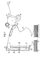
- FIG. 1 shows a basic structure of an electrophotographic high-speed printer.
- a drum 10 with a photoelectric surface is evenly charged by means of a corotron 12.
- a character generator 14 e.g. a controlled light beam generated by a laser charge images of the characters to be printed on the drum 10.
- the charge images are then processed in a developer station 16 e.g. developed according to the magnetic brush principle.
- a transfer printing station 18 the toner images of the characters to be printed, which are now arranged on the surface of the drum 10, are placed on a recording medium 20, e.g. a paper web, reprinted.
- the recording medium 20 is brought up to the surface of the drum 10.
- the recording medium 20 is then passed through a fixing station 22.
- the structure of the fixing station 22 is e.g. described in more detail in DE-OS 28 38 864.
- the fixing station 22 initially consists of a container 24, in the bottom surface of which a heating device 26 is arranged. A solvent located at the bottom of the container 24 is evaporated by heating. In order to prevent the solvent vapor from escaping from the container 24, cooling coils 28 are arranged in the upper region of the container 24. In this area, the solvent vapor condenses and drips back to the bottom of the container.
- the recording medium 20 is guided through the container 24 with the aid of a fixing roller 30. If it is to be fixed, the fixing roller 30 is in position I. The recording medium 20 is thus in the area of the solvent vapor, which can act on the recording medium and the toner image applied thereon. During printing breaks, it is advisable to remove the recording medium 20 from the area of the solvent vapor.
- the fixing roller 30 is moved upward in the container 24 and brought into the area of the cooling coils, 28, specifically into position II. There, the fixing roller 30 can cool down. If printing operation now follows again, then the fixing roller 30 is brought back into position I. Then, it is inevitable that 30 solvent vapor condenses on the surface of the fixing roller. This continues until the temperature of the fusing roller has adjusted to above the dew point. If the recording medium 20 is guided directly over the surface of the fixing roller 30, then this absorbs the condensate on the surface of the fixing roller 30 and transports it out of the container 24.
- a wire helix 32 is arranged on the surface of the fixing roller 30.
- This consists of a with PTFE, e.g. Teflon. insulated wire, which is wound from about a fastening point 34 on the fixing roller 30, which is / in the middle of the fixing roller, to the end faces 36 and 38 thereof in a screw form and is also fastened there.
- the direction of winding is selected such that the condensate collecting due to gravity in the lower region of the fixing roller diameter moves to the two end faces during the rotation of the fixing roller and drips from there.
- the cross section of the wire helix 32 is selected to be circular.
- a tapering gap 40 is formed between the wire 32 and the surface of the fixing roller. Due to capillary forces, this gap only fills up to the contact angle typical of the combination of PTFE and solvent. This is shown in FIG. 3 at point 42. This prevents the condensate from passing over to the recording medium 30.
- the condensate migrates to the gaps 40 between the wire helix 32 and the surface of the fixing roller 30.
- selected - Ste Trent.der wire coil moves the condensate to the wire helix along outwardly to the end faces 36 and 38 that drips fixing roller and / there to the bottom of the container 24. A transition of the condensate from the surface of the fixing roller 30 to the recording medium 20 is thus prevented.
Landscapes
- Physics & Mathematics (AREA)
- General Physics & Mathematics (AREA)
- Fixing For Electrophotography (AREA)
Priority Applications (1)
| Application Number | Priority Date | Filing Date | Title |
|---|---|---|---|
| AT81107986T ATE8305T1 (de) | 1980-12-22 | 1981-10-06 | Fixierwalze. |
Applications Claiming Priority (2)
| Application Number | Priority Date | Filing Date | Title |
|---|---|---|---|
| DE3048477 | 1980-12-22 | ||
| DE3048477A DE3048477C2 (de) | 1980-12-22 | 1980-12-22 | Fixierwalze |
Publications (2)
| Publication Number | Publication Date |
|---|---|
| EP0056079A1 true EP0056079A1 (fr) | 1982-07-21 |
| EP0056079B1 EP0056079B1 (fr) | 1984-07-04 |
Family
ID=6119951
Family Applications (1)
| Application Number | Title | Priority Date | Filing Date |
|---|---|---|---|
| EP81107986A Expired EP0056079B1 (fr) | 1980-12-22 | 1981-10-06 | Rouleau de fixage |
Country Status (4)
| Country | Link |
|---|---|
| EP (1) | EP0056079B1 (fr) |
| JP (1) | JPS57135966A (fr) |
| AT (1) | ATE8305T1 (fr) |
| DE (1) | DE3048477C2 (fr) |
Cited By (2)
| Publication number | Priority date | Publication date | Assignee | Title |
|---|---|---|---|---|
| EP0115866A1 (fr) * | 1983-02-07 | 1984-08-15 | Siemens Aktiengesellschaft | Rouleau d'entraînement de papier pour une installation d'impression ou de copie fonctionnant suivant le principe de l'électrophotographie |
| EP0154695A1 (fr) * | 1984-02-21 | 1985-09-18 | Siemens Aktiengesellschaft | Dispositif non-mécanique d'impression ou de copiage pour plusieurs couleurs et recto-verso |
Families Citing this family (2)
| Publication number | Priority date | Publication date | Assignee | Title |
|---|---|---|---|---|
| US5008716A (en) * | 1989-10-05 | 1991-04-16 | Hitachi Koki Co., Ltd. | Paper cooling apparatus for an electrophotographic printer |
| JP3290513B2 (ja) * | 1993-07-29 | 2002-06-10 | ユニコ株式会社 | トナーの湿式定着方法 |
Citations (3)
| Publication number | Priority date | Publication date | Assignee | Title |
|---|---|---|---|---|
| US3140160A (en) * | 1956-12-03 | 1964-07-07 | Xerox Corp | Xerographic fusing and drying apparatus |
| US3383775A (en) * | 1966-11-25 | 1968-05-21 | Continental Can Co | Hot vapor fixing of fusible powder images with azeotropic mixtures |
| EP0008650A1 (fr) * | 1978-09-06 | 1980-03-19 | Siemens Aktiengesellschaft | Dispositif pour la fixation d'images de toner sur un support d'enregistrement à l'aide de vapeur de solvant |
-
1980
- 1980-12-22 DE DE3048477A patent/DE3048477C2/de not_active Expired
-
1981
- 1981-10-06 EP EP81107986A patent/EP0056079B1/fr not_active Expired
- 1981-10-06 AT AT81107986T patent/ATE8305T1/de not_active IP Right Cessation
- 1981-12-22 JP JP56209002A patent/JPS57135966A/ja active Pending
Patent Citations (4)
| Publication number | Priority date | Publication date | Assignee | Title |
|---|---|---|---|---|
| US3140160A (en) * | 1956-12-03 | 1964-07-07 | Xerox Corp | Xerographic fusing and drying apparatus |
| US3383775A (en) * | 1966-11-25 | 1968-05-21 | Continental Can Co | Hot vapor fixing of fusible powder images with azeotropic mixtures |
| EP0008650A1 (fr) * | 1978-09-06 | 1980-03-19 | Siemens Aktiengesellschaft | Dispositif pour la fixation d'images de toner sur un support d'enregistrement à l'aide de vapeur de solvant |
| DE2838864A1 (de) * | 1978-09-06 | 1980-03-20 | Siemens Ag | Vorrichtung zur fixierung von auf einem aufzeichnungstraeger aufgebrachten bildern aus pulverfoermigen toner mit hilfe von loesungsmitteldampf |
Cited By (2)
| Publication number | Priority date | Publication date | Assignee | Title |
|---|---|---|---|---|
| EP0115866A1 (fr) * | 1983-02-07 | 1984-08-15 | Siemens Aktiengesellschaft | Rouleau d'entraînement de papier pour une installation d'impression ou de copie fonctionnant suivant le principe de l'électrophotographie |
| EP0154695A1 (fr) * | 1984-02-21 | 1985-09-18 | Siemens Aktiengesellschaft | Dispositif non-mécanique d'impression ou de copiage pour plusieurs couleurs et recto-verso |
Also Published As
| Publication number | Publication date |
|---|---|
| EP0056079B1 (fr) | 1984-07-04 |
| ATE8305T1 (de) | 1984-07-15 |
| DE3048477C2 (de) | 1982-10-28 |
| DE3048477A1 (de) | 1982-07-01 |
| JPS57135966A (en) | 1982-08-21 |
Similar Documents
| Publication | Publication Date | Title |
|---|---|---|
| DE2703382C3 (de) | Vorrichtung zur Zuführung von Trennflüssigkeit zur Oberfläche einer Fixierwalze | |
| DE3507114A1 (de) | Bildaufzeichnungsvorrichtung | |
| DE68921575T2 (de) | Aufnahmegerät. | |
| EP0401208A1 (fr) | Procede et dispositif d'impression par encrage d'une image virtuelle. | |
| DE2729005A1 (de) | Magnetbuerstenrolle | |
| DE2908759C2 (de) | Verfahren und Vorrichtung zum Naßentwickeln eines auf einem Bildträger vorhandenen elektrostatischen Ladungsbilds | |
| DE3816929A1 (de) | Drucker | |
| EP0056079B1 (fr) | Rouleau de fixage | |
| EP0008650B1 (fr) | Dispositif pour la fixation d'images de toner sur un support d'enregistrement à l'aide de vapeur de solvant | |
| DE69110360T2 (de) | Elektrophotographisches Druckgerät. | |
| DE2821964C3 (de) | Verfahren zur Kontaktierung eines Bildempfangsmaterials mit einem Bildträger sowie Übertragungs-Koronavorrichtung zur Durchführung eines solchen Verfahrens | |
| DE69418257T2 (de) | Trennmittelzufuhrsystem | |
| DE2750612A1 (de) | Vorrichtung zum umdruck von auf einem staendig umlaufenden bandfoermigen zwischentraeger aufgebrachten zeichen aus toner auf einen senkrecht zum zwischentraeger bewegten aufzeichnungstraeger | |
| DE2164287A1 (de) | Vorrichtung zur Einschmelzfixierung elektroskopischer Tonerbilder | |
| EP0115866B1 (fr) | Rouleau d'entraînement de papier pour une installation d'impression ou de copie fonctionnant suivant le principe de l'électrophotographie | |
| DE3436648C2 (fr) | ||
| DE69218890T2 (de) | Zylindrisches Element und damit ausgestattetes elektrophotographisches Gerät | |
| DE4435077A1 (de) | Schnell schaltbare und höchstgeschwindigkeitsfähige Infrarotfixierung elektrografischer Tonerbilder | |
| EP0876638B1 (fr) | Dispositif pour l'application d'un agent separateur a la surface d'un rouleau de fixage d'une machine d'impression ou de copiage electrographique | |
| DE3811413A1 (de) | Einrichtung zur bildaufzeichnung | |
| DE3831789A1 (de) | Bilderzeugungsgeraet | |
| DE3615387C2 (fr) | ||
| DE2917162A1 (de) | Verfahren und vorrichtung zur fluessigkeitsbehandlung | |
| DE2551064A1 (de) | Schmelzfixiervorrichtung fuer tonerbilder | |
| DE2946206A1 (de) | Vorrichtung zur bestimmung der tonerdichte bei einem elektrostatischen aufzeichnungsgeraet o.dgl. |
Legal Events
| Date | Code | Title | Description |
|---|---|---|---|
| PUAI | Public reference made under article 153(3) epc to a published international application that has entered the european phase |
Free format text: ORIGINAL CODE: 0009012 |
|
| 17P | Request for examination filed |
Effective date: 19811006 |
|
| AK | Designated contracting states |
Designated state(s): AT BE CH FR GB IT NL SE |
|
| GRAA | (expected) grant |
Free format text: ORIGINAL CODE: 0009210 |
|
| AK | Designated contracting states |
Designated state(s): AT BE CH FR GB IT LI NL SE |
|
| PG25 | Lapsed in a contracting state [announced via postgrant information from national office to epo] |
Ref country code: SE Effective date: 19840704 Ref country code: NL Effective date: 19840704 Ref country code: IT Free format text: LAPSE BECAUSE OF FAILURE TO SUBMIT A TRANSLATION OF THE DESCRIPTION OR TO PAY THE FEE WITHIN THE PRESCRIBED TIME-LIMIT;WARNING: LAPSES OF ITALIAN PATENTS WITH EFFECTIVE DATE BEFORE 2007 MAY HAVE OCCURRED AT ANY TIME BEFORE 2007. THE CORRECT EFFECTIVE DATE MAY BE DIFFERENT FROM THE ONE RECORDED. Effective date: 19840704 Ref country code: FR Free format text: THE PATENT HAS BEEN ANNULLED BY A DECISION OF A NATIONAL AUTHORITY Effective date: 19840704 Ref country code: BE Effective date: 19840704 |
|
| REF | Corresponds to: |
Ref document number: 8305 Country of ref document: AT Date of ref document: 19840715 Kind code of ref document: T |
|
| PG25 | Lapsed in a contracting state [announced via postgrant information from national office to epo] |
Ref country code: AT Effective date: 19841006 |
|
| PG25 | Lapsed in a contracting state [announced via postgrant information from national office to epo] |
Ref country code: LI Effective date: 19841031 Ref country code: CH Effective date: 19841031 |
|
| NLV1 | Nl: lapsed or annulled due to failure to fulfill the requirements of art. 29p and 29m of the patents act | ||
| PLBE | No opposition filed within time limit |
Free format text: ORIGINAL CODE: 0009261 |
|
| STAA | Information on the status of an ep patent application or granted ep patent |
Free format text: STATUS: NO OPPOSITION FILED WITHIN TIME LIMIT |
|
| REG | Reference to a national code |
Ref country code: CH Ref legal event code: PL |
|
| 26N | No opposition filed | ||
| EN | Fr: translation not filed | ||
| PG25 | Lapsed in a contracting state [announced via postgrant information from national office to epo] |
Ref country code: GB Effective date: 19881006 |
|
| GBPC | Gb: european patent ceased through non-payment of renewal fee |