EP0056097A2 - Process for mounting a contact wire and appropriate contact wire therefor - Google Patents
Process for mounting a contact wire and appropriate contact wire therefor Download PDFInfo
- Publication number
- EP0056097A2 EP0056097A2 EP81109172A EP81109172A EP0056097A2 EP 0056097 A2 EP0056097 A2 EP 0056097A2 EP 81109172 A EP81109172 A EP 81109172A EP 81109172 A EP81109172 A EP 81109172A EP 0056097 A2 EP0056097 A2 EP 0056097A2
- Authority
- EP
- European Patent Office
- Prior art keywords
- profile
- contact wire
- clamping
- conductor line
- conductor
- Prior art date
- Legal status (The legal status is an assumption and is not a legal conclusion. Google has not performed a legal analysis and makes no representation as to the accuracy of the status listed.)
- Withdrawn
Links
- 238000000034 method Methods 0.000 title claims abstract description 14
- 239000004020 conductor Substances 0.000 claims abstract description 43
- 239000000463 material Substances 0.000 claims abstract description 18
- 229910052802 copper Inorganic materials 0.000 claims abstract description 9
- 239000010949 copper Substances 0.000 claims abstract description 9
- RYGMFSIKBFXOCR-UHFFFAOYSA-N Copper Chemical compound [Cu] RYGMFSIKBFXOCR-UHFFFAOYSA-N 0.000 claims abstract description 8
- 229910000831 Steel Inorganic materials 0.000 claims abstract description 6
- 239000010959 steel Substances 0.000 claims abstract description 6
- 238000005096 rolling process Methods 0.000 claims abstract description 5
- 238000004026 adhesive bonding Methods 0.000 claims description 4
- 238000005476 soldering Methods 0.000 claims description 4
- 229910001069 Ti alloy Inorganic materials 0.000 claims description 3
- 229910000881 Cu alloy Inorganic materials 0.000 claims description 2
- 239000011248 coating agent Substances 0.000 claims 1
- 238000000576 coating method Methods 0.000 claims 1
- 238000005260 corrosion Methods 0.000 claims 1
- 230000007797 corrosion Effects 0.000 claims 1
- 238000004519 manufacturing process Methods 0.000 description 4
- 238000013461 design Methods 0.000 description 3
- XEEYBQQBJWHFJM-UHFFFAOYSA-N Iron Chemical compound [Fe] XEEYBQQBJWHFJM-UHFFFAOYSA-N 0.000 description 2
- 238000005299 abrasion Methods 0.000 description 2
- 238000013459 approach Methods 0.000 description 2
- 239000011324 bead Substances 0.000 description 2
- 229910052751 metal Inorganic materials 0.000 description 2
- 239000002184 metal Substances 0.000 description 2
- 229910000967 As alloy Inorganic materials 0.000 description 1
- 229910000952 Be alloy Inorganic materials 0.000 description 1
- 238000005452 bending Methods 0.000 description 1
- ATBAMAFKBVZNFJ-UHFFFAOYSA-N beryllium atom Chemical compound [Be] ATBAMAFKBVZNFJ-UHFFFAOYSA-N 0.000 description 1
- 238000005520 cutting process Methods 0.000 description 1
- 238000011161 development Methods 0.000 description 1
- 238000005516 engineering process Methods 0.000 description 1
- 238000001125 extrusion Methods 0.000 description 1
- 238000009434 installation Methods 0.000 description 1
- 229910052742 iron Inorganic materials 0.000 description 1
- 230000003137 locomotive effect Effects 0.000 description 1
- 239000000725 suspension Substances 0.000 description 1
- 238000012549 training Methods 0.000 description 1
- 238000003466 welding Methods 0.000 description 1
- 238000004804 winding Methods 0.000 description 1
Images


Classifications
-
- B—PERFORMING OPERATIONS; TRANSPORTING
- B60—VEHICLES IN GENERAL
- B60M—POWER SUPPLY LINES, AND DEVICES ALONG RAILS, FOR ELECTRICALLY- PROPELLED VEHICLES
- B60M1/00—Power supply lines for contact with collector on vehicle
- B60M1/12—Trolley lines; Accessories therefor
- B60M1/28—Manufacturing or repairing trolley lines
-
- B—PERFORMING OPERATIONS; TRANSPORTING
- B60—VEHICLES IN GENERAL
- B60M—POWER SUPPLY LINES, AND DEVICES ALONG RAILS, FOR ELECTRICALLY- PROPELLED VEHICLES
- B60M1/00—Power supply lines for contact with collector on vehicle
- B60M1/12—Trolley lines; Accessories therefor
- B60M1/13—Trolley wires
- B60M1/135—Trolley wires composite
Definitions
- the invention relates to a method for assembling a contact wire and a suitable contact wire therefor, in particular for electrically operated high-speed railways, the contact wire comprising two components running in parallel has, namely a low-tension current-carrying conductor line profile made of a highly conductive material, in particular copper or a copper alloy, and a tension profile made of a high-tensile material, especially steel or a titanium alloy.
- the overhead contact line system particularly in the vertical direction, has quite considerable vibrations, which lead to spark gaps between the contact wire and the current bracket of the electric locomotive and can therefore cause considerable wear and tear.
- These undesirable vibrations can e.g. dampen by laying the contact wire under very high tension.
- materials for the contact wire are required with very high strength, such as Alloys of copper / beryllium or steel coated with a copper layer, e.g. "Staku" (according to DIN).
- DE-PS 536 656 describes a contact wire with a relatively hard core metal made of iron or steel with high tensile strength, which is surrounded by a closed jacket made of softer, highly conductive metal, such as copper is. In this approach, the attempt was made to distribute the complex requirements for a contact wire over two material components with different material properties.
- the invention has for its object to improve the prior art while avoiding the disadvantages indicated above and a method for mounting a contact wire and the contact wire suitable for this purpose itself
- a high-speed overhead line with very low vibration results which can be applied to conventional overhead line or support systems due to its moderate weight and is easy to assemble
- the contact line component subject to abrasion is designed as interchangeable as possible without bracing the under high Tensioning supporting component required.
- the conductor rail profile can be continuously unwound from a drum or the like located on a track assembly carriage and deflected by a first roller of the tool and pressed onto the clamping profile by further rollers and connected to it in a form-fitting manner.
- clamping in sections can be advantageous for safety reasons, but this is not always necessary. Both in the case of the form-fitting connection extending over the entire length and in the case of a connection by gluing or soldering or the like, rapid disassembly can be possible, in particular by means of wedging, so that the worn conductor line profile can be easily replaced by a new one without unclamping the suspension cable can be replaced over the entire span.
- two parallel components namely a low-tension current-carrying conductor line profile made of a highly conductive material such as e.g. E-copper, F-20 or F-37 (according to DIN) and a clamping profile made of a high-tensile material, especially steel or a titanium alloy.
- a low-tension current-carrying conductor line profile made of a highly conductive material such as e.g. E-copper, F-20 or F-37 (according to DIN)
- a clamping profile made of a high-tensile material, especially steel or a titanium alloy.
- the development of the contact wire according to the invention consists in the fact that the tensioning profile in the upper area facing the catenary or support system has a conventional clamping or groove profile for connection to the support system and in the central area notches on both sides for direct positive connection with the below the tensioning profile provided conductor line profile.
- the profiles or notches can extend over the entire length of the clamping profile or the conductor line profile, particularly if the profile is produced by extrusion or drawing, so that the positive connection is provided over the entire length of the contact line.
- FIG. 1 shows an embodiment of the method according to the invention, the actual assembly carriage 40 having a hydraulically height-adjustable working platform 42 on which the rolling tool 44 can be mounted or supported.
- the assembly tool for the positive connection of the grinding guide profile 20 to the clamping profile 10 can also work without support on the work platform. It preferably has a deflecting roller in the part facing the drum 48 and at least two pressure rollers on each side, in order to expand it to be able to press the present conductor line profile 20 accordingly. At least one counter roller must be provided above the contact wire.
- the prefabricated conductor line profile 20 is pulled off the drum 48, which in turn is either mounted on the assembly carriage 40 or a second carriage 46 in front of this.
- Figure 2 shows a vertical cross section through the finished contact wire.
- the conductor rail profile shown in FIG. 3 in the prefabricated state is now form-fitting with the clamping profile 10. connected as a result of reeling and rolling of the two tabs 22 into the correspondingly shaped notches 14 of the clamping profile.
- the notch 16 is attached in the lower surface of the clamping profile 10 so that a cutting of the laterally worn conductor line profile 20 along the center line shown e.g. by means of a rotating saw, after which the two halves of the conductor line profile can be easily removed.
- the clamping profile 10 shows a conventional groove profile 12.
Landscapes
- Engineering & Computer Science (AREA)
- Mechanical Engineering (AREA)
- Manufacturing & Machinery (AREA)
- Machines For Laying And Maintaining Railways (AREA)
- Suspension Of Electric Lines Or Cables (AREA)
- Connections Effected By Soldering, Adhesion, Or Permanent Deformation (AREA)
Abstract
Die Erfindung betrifft ein Verfahren zur Montage eines Fahrdrahtes, insbesondere für elektrisch betriebene Schnellbahnen, sowie den Fahrdraht selbst. Der Fahrdraht weist zwei parallellaufende Komponenten auf, nämlich ein zugspannungsarmes stromführendes Schleifleitungsprofil insbesondere aus Kupfer, und ein Spannprofil aus einem hochzugfesten Werkstoff wie Stahl. Es wird zunächst das Spannprofil montiert und unter hohe Zugspannung gesetzt. Anschließend wird das Schleifleitungsprofil vor Ort einstückig und unmittelbar auf das Spannprofil formschlüssig aufgebracht, bevorzugt mittels Rollwerkzeug.The invention relates to a method for assembling a contact wire, in particular for electrically operated high-speed railways, and the contact wire itself. The contact wire has two components running in parallel, namely a low-tension, current-carrying conductor line profile, in particular made of copper, and a tension profile made of a high-tensile material such as steel. The clamping profile is first installed and placed under high tensile stress. Subsequently, the conductor rail profile is applied in one piece and directly in a form-fitting manner on site, preferably using a rolling tool.
Das Spannprofil (10) hat im oberen Bereich ein übliches Rillenprofil (12) zur Verbindung mit dem Drahtsystem (30) und im mittleren Bereich beidseitig Einkerbungen (14) zur formschlüssigen Verbindung mit dem Schleifleitungsprofil (20), das vorzugsweise die Form eines elliptischen oder Kreis-Segmentes aufweist mit zwei seitlich angeformten Lappen (22).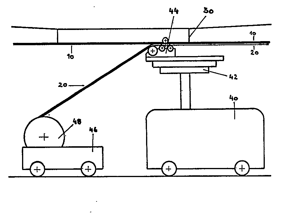
Description
Die Erfindung betrifft ein Verfahren zur Montage eines Fahrdrahtes sowie einen geeigneten Fahrdraht hierzu, insbesondere für elektrisch betriebene Schnellbahnen, wobei der Fahrdraht zwei parallellaufende Komponenten aufweist, nämlich ein zugspannungsarmes stromführendes Schleifleitungsprofil aus einem gutleitenden Werkstoff, insbesondere Kupfer oder einer Kupfer-Legierung, und ein Spannprofil aus einem hochzugfesten Werkstoff, insbesondere Stahl oder einer Titan-Legierung.The invention relates to a method for assembling a contact wire and a suitable contact wire therefor, in particular for electrically operated high-speed railways, the contact wire comprising two components running in parallel has, namely a low-tension current-carrying conductor line profile made of a highly conductive material, in particular copper or a copper alloy, and a tension profile made of a high-tensile material, especially steel or a titanium alloy.
Bei Fahrgeschwindigkeiten im Bereich oberhalb 300 km/h wie sie heute für Eisenbahnen geplant.werden, treten im Fahrleitungssystem insbesondere in vertikaler Richtung eine recht erhebliche Schwingungen auf, die zu Funkenstrecken zwischen dem Fahrdraht und dem Strombügel der Elektrolokomotive führen und somit erheblichen Verschleiß verursachen können. Diese unerwünschten Schwingungen kann man z.B. dadurch dämpfen, daß man den Fahrdraht unter sehr hoher Zugspannung verlegt. In diesem Falle werden dann Werkstoffe für den Fahrdraht benötigt mit sehr hoher Festigkeit wie z.B. Legierungen aus Kupfer/ Beryllium oder mit einer Kupferschicht überzogener Stahl wie z.B. "Staku" (nach DIN).At speeds in the range above 300 km / h, as are currently planned for railways, the overhead contact line system, particularly in the vertical direction, has quite considerable vibrations, which lead to spark gaps between the contact wire and the current bracket of the electric locomotive and can therefore cause considerable wear and tear. These undesirable vibrations can e.g. dampen by laying the contact wire under very high tension. In this case, materials for the contact wire are required with very high strength, such as Alloys of copper / beryllium or steel coated with a copper layer, e.g. "Staku" (according to DIN).
Solche Werkstoffe haben allerdings den Nachteil, daß ihre Fertigungstechnologie sehr anspruchsvoll und demgemäß ihre Herstellung kostspielig und ihre Beschaffung schwierig ist. Darüber hinaus treten wegen der hohen Biegesteifigkeit dieser Werkstoffe bei der Montage des Fahrdrahtes erhebliche Probleme auf. In der DE-PS 536 656 ist ein Fahrdraht beschrieben, mit einem relativ harten Kernmetall aus Eisen oder Stahl mit hoher Zugfestigkeit, des ringsum von einem geschlossenen Mantel aus weicherem, gutleitendem Metall, wie Kupfer, umgeben ist. Hier ist im Ansatz der Versuch gemacht, die komplexen Anforderungen an einen Fahrdraht auf zwei Materialkomponenten mit verschiedenen Materialeigenschaften zu verteilen.However, such materials have the disadvantage that their manufacturing technology is very demanding and accordingly their production is expensive and their procurement is difficult. In addition, due to the high bending stiffness of these materials, considerable problems arise when installing the contact wire. DE-PS 536 656 describes a contact wire with a relatively hard core metal made of iron or steel with high tensile strength, which is surrounded by a closed jacket made of softer, highly conductive metal, such as copper is. In this approach, the attempt was made to distribute the complex requirements for a contact wire over two material components with different material properties.
Noch deutlicher ist dieser Ansatz bei der DE-PS 535 464, wo Seile aus einem hochleitenden (relativ weichen) Werkstoff kombiniert sind mit einer Schleifleitung aus abriebfesterem Werkstoff, wobei diese Schleifleitung leicht auswechselbar und aus einzelnen Stücken bestehen soll. Die Herstellung der Schleifleitung aus einzelnen Stücken sollte die Montage erleichtern und einer übermäßigen Versteifung der Fahrleitung entgegenwirken. Es wird zunächst das Seil verlegt und gespannt. Dann werden die einzelnen Stücke der Schleifleitung an das eigentliche hochleitende Fahrseil durch eine Vielzahl von Klemmstücken in montageintensiver Weise angebracht.This approach is even clearer in DE-PS 535 464, where ropes made of a highly conductive (relatively soft) material are combined with a conductor line made of more abrasion-resistant material, this conductor line should be easily replaceable and should consist of individual pieces. The manufacture of the conductor rail from individual pieces should make assembly easier and counteract excessive stiffening of the overhead contact line. First the rope is laid and tensioned. Then the individual pieces of the conductor rail are attached to the actual highly conductive traction rope by a large number of clamping pieces in an assembly-intensive manner.
Die Nachteile der letztgenannten Fahrdraht-Ausbildung selbst liegen - abgesehen von der dort nicht vorgesehen Verwendung eines hochzugfesten Materials - darin, daß das Gesamtgewicht des kombinierten Fahrdrahtes zu schwer und damit das erforderliche Tragsystem zu teuer wird. Im übrigen ist die dort genannte Materialauswahl und vielstückige Ausbildung der Schleifleitung für einen Hochgeschwindigkeits-Fahrdraht ebenfalls nicht geeignet.The disadvantages of the last-mentioned contact wire training itself - apart from the use of a high-tensile material not provided there - is that the total weight of the combined contact wire is too heavy and the supporting system thus becomes too expensive. Otherwise, the selection of materials mentioned there and the multi-piece design of the conductor rail are also unsuitable for a high-speed contact wire.
Der Erfindung liegt die Aufgabe zugrunde, den Stand der Technik unter Vermeidung der oben angedeuteten Nachteile zu verbessern und ein Verfahren zur Montage eines Fahrdrahtes sowie den hierzu geeigneten Fahrdraht selbst in solcher Weise bereitzustellen, daß eine Hochgeschwindigkeits-Fahrleitung mit sehr geringer Schwingung resultiert, welche in Folge mäßigen Gewichtes auf herkömmliche Fahrleitungs- bzw. Tragsysteme anwendbar und leicht montierbar ist, und daß die dem Abrieb unterliegende Schleifleitungskomponente möglichst auswechselbar ausgestaltet ist ohne eine Abspannung der unter hoher Spannung stehenden Tragkomponente erforderlich zu machen.The invention has for its object to improve the prior art while avoiding the disadvantages indicated above and a method for mounting a contact wire and the contact wire suitable for this purpose itself To be provided in such a way that a high-speed overhead line with very low vibration results, which can be applied to conventional overhead line or support systems due to its moderate weight and is easy to assemble, and that the contact line component subject to abrasion is designed as interchangeable as possible without bracing the under high Tensioning supporting component required.
Diese Aufgabe wird im Falle eines Verfahrens der eingangs genannten Art nach der Erfindung dadurch gelöst, daß an das Fahrleitungssystem zunächst das Spannprofil in an sich bekannter Weise montiert und unter die für die geringe Schwingungsamplitude erforderliche hohe Zugspannung gesetzt wird, worauf das Schleifleitungsprofil vor Ort einstückig (in bezug auf die jeweilige Abspannlänge) und unmittelbar auf das Spannprofil formschlüssig aufgebracht wird, vorzugsweise mittels eines Rollwerkzeuges.This object is achieved in the case of a method of the type mentioned at the outset according to the invention in that the tensioning profile is first mounted on the overhead contact line system in a manner known per se and is placed under the high tensile stress required for the low vibration amplitude, whereupon the conductor line profile is made in one piece on site ( with respect to the respective guy length) and directly applied to the clamping profile in a form-fitting manner, preferably by means of a rolling tool.
Bei einer bevorzugten Ausführungsform der Erfindung, kann das Schleifleitungsprofil kontinuierlich von einer auf einem Gleismontagewagen befindlichen Trommel oder dgl. abgewickelt und von einer ersten Rolle des Werkzeuges umgelenkt und durch weitere Rollen an das Spannprofil angedrückt und mit diesem formschlüssig verbunden werden.In a preferred embodiment of the invention, the conductor rail profile can be continuously unwound from a drum or the like located on a track assembly carriage and deflected by a first roller of the tool and pressed onto the clamping profile by further rollers and connected to it in a form-fitting manner.
In den meisten Fällen ist es von Vorteil, entsprechend gestaltete, für die formschlüssige Verbindung geeignete Profile zu verwenden. Eine kostengünstigere, allerdings unter technischen Gesichtspunkten nicht ganz so befriedigende noch im Rahmen der Erfindung liegende Ausführungsform geht dahin, daß unter Verwendung einfacherer Formen das Schleifleitungsprofil ggf. ohne formschlüssige Verbindung an das Spannprofil von unten mittels Kleben, Löten oder auch Schweißen erfolgt.In most cases, it is advantageous to use appropriately designed profiles that are suitable for the positive connection. A less expensive, but not quite as satisfactory from the technical point of view still within the scope of the invention is that using simpler shapes, the conductor line profile, if necessary, without a positive connection to the clamping profile from below by gluing, soldering or welding.
In Verbindung hiermit kann ein abschnittsweise erfolgendes Festklemmen schon aus Sicherheitsgründen vorteilhaft sein, doch ist dies nicht in jedem Falle erforderlich. Sowohl im Falle der formschlüssigen sich über die ganze Länge erstreckende Verbindung als auch im Falle einer Verbindung durch Kleben oder Löten oder dgl. kann eine rasche Demontage insbesondere mittels Aufkeilen möglich sein, so daß ohne großen Aufwand das abgenutzte Schleifleitungsprofil durch ein neues ohne Abspannen des Tragseiles über die jeweilige gesamte Abspannstrecke ersetzbar ist.In connection with this, clamping in sections can be advantageous for safety reasons, but this is not always necessary. Both in the case of the form-fitting connection extending over the entire length and in the case of a connection by gluing or soldering or the like, rapid disassembly can be possible, in particular by means of wedging, so that the worn conductor line profile can be easily replaced by a new one without unclamping the suspension cable can be replaced over the entire span.
Bei der Gestaltung des Fahrdrahtes zur Verwendung für das erfindungsgemäße Verfahren wird von zwei parallellaufenden Komponenten, nämlich einem zugspannungsarmen stromführenden Schleifleitungsprofil aus einem gutleitenden Werkstoff wie z.B. E-Kupfer, F-20 oder F-37 (nach DIN) ausgegangen und einem Spannprofil aus einem hochzugfesten Werkstoff, insbesondere aus Stahl oder einer Titan-Legierung.When designing the contact wire for use in the method according to the invention, two parallel components, namely a low-tension current-carrying conductor line profile made of a highly conductive material such as e.g. E-copper, F-20 or F-37 (according to DIN) and a clamping profile made of a high-tensile material, especially steel or a titanium alloy.
Die erfindungsgemäße Weiterbildung des Fahrdrahtes besteht darin, daß das Spannprofil im oberen, dem Fahrleitungs- bzw. Tragsystem zugewandten Bereich ein übliches Klemm- bzw. Rillenprofil zur Verbindung mit dem Tragsystem und im mittleren Bereich beidseitig Einkerbungen aufweist zur unmittelbaren formschlüssigen Verbindung mit dem unterhalb des Spannprofiles vorgesehenen Schleifleitungsprofil.The development of the contact wire according to the invention consists in the fact that the tensioning profile in the upper area facing the catenary or support system has a conventional clamping or groove profile for connection to the support system and in the central area notches on both sides for direct positive connection with the below the tensioning profile provided conductor line profile.
Die Profilierungen bzw. Einkerbungen können sich, insbesondere wenn das Profil im Strangpress- oder Ziehverfahren hergestellt ist, über die gesamte Länge des Spannprofiles bzw. des Schleifleitungsprofiles erstrecken, so daß die formschlüssige Verbindung über die gesamte Fahrleitungslänge gegeben ist.The profiles or notches can extend over the entire length of the clamping profile or the conductor line profile, particularly if the profile is produced by extrusion or drawing, so that the positive connection is provided over the entire length of the contact line.
Grundsätzlich ist es jedoch auch möglich, daß diese formschlüssige Verbindung bzw. die hierfür erforderliche Einkerbung nicht durchgehend, sondern nur in Abständen erfolgt.In principle, however, it is also possible that this positive connection or the notch required for this is not carried out continuously, but only at intervals.
Weitere erfindungsgemäße Ausgestaltungen des Fahrdrahtes und seiner Komponenten sind in den Unteransprüchen gekennzeichnet.Further embodiments of the contact wire and its components according to the invention are characterized in the subclaims.
Zwar ist es bereits bekanntgeworden in Verbindung mit Fahrdrahtabschnitten einen Kupferwulst auf ein T-Profil, das auch aus einem anderen Material sein kann, aufzuwalzen (vgl. DE-PS 959 831). Jedoch handelt es sich dort um Fahrdrahtabschnitte, die nicht unter Zugspannung stehen und denen nicht eine mit dem vorliegenden Gegenstand vergleichbare Aufgabe zugrunde liegt. Auch wird der Kupferwulst so aufgewalzt, daß nach seiner Abnutzung das ganze Profil ausgewechselt werden muß. Eine Anregung in Richtung des erfindungsgemäßen Fahrdrahtes und seiner spezifischen Gestaltung ist daher nicht zu entnehmen.It has already become known in connection with contact wire sections to roll a copper bead onto a T-profile, which can also be made of a different material (cf. DE-PS 959 831). However, there are contact wire sections which are not under tension and which are not based on a task comparable to the present subject. The copper bead is also rolled on so that the entire profile has to be replaced after it has worn out. A suggestion in the direction of the contact wire according to the invention and its specific design is therefore not apparent.
Im folgenden wird die Erfindung anhand eines Ausführungsbeispieles näher beschrieben, aus dem sich weitere Merkmale und Vorteile der Erfindung entnehmen lassen.
- Fig. 1 zeigt die Durchführung des erfindungsgemäßen Verfahrens mittels Montagewagen;
- Fig. 2 zeigt einen senkrechten Querschnitt durch den fertiggestellten Fahrdraht;
- Fig. 3 zeigt einen senkrechten Querschnitt durch das Schleifleitungsprofil im vorgefertigten (nicht montierten) Zustand.
- Fig. 1 shows the implementation of the method according to the invention by means of assembly car;
- Fig. 2 shows a vertical cross section through the finished contact wire;
- Fig. 3 shows a vertical cross section through the conductor rail profile in the prefabricated (not assembled) state.
Figur 1 zeigt eine Durchführungsform des erfindungsgemäßen Verfahrens, wobei der eigentliche Montagewagen 40 eine hydraulisch höhenverstellbare Arbeitsbühne 42 aufweist, auf welcher das Rollwerkzeug 44 montiert bzw. abstützt sein kann. Grundsätzlich kann das Montage-Werkzeug zum formschlüssigen Verbinden des Schleifleitprofiles 20 mit dem Spannprofil 10 auch ohne Abstützung auf der Arbeitsbühne arbeiten.Es weist vorzugsweise eine Umlenkrolle im vorderen der.Trommel 48 zugewandten Teil auf sowie seitlich je mindestens zwei Anpressrollen,um das in aufgespreizter Form vorliegende Schleifleitungsprofil 20 entsprechend anpressen zu können. Oberhalb des Fahrdrahtes ist mindestens eine Gegenrolle vorzusehen. Während der weitgehend kontiniuierlich möglichen Montage wird das vorgefertigte Schleifleitungsprofil 20 von der Trommel 48 abgezogen, die ihrerseits entweder auf dem Montagewagen 40 gelagert ist oder einem zweiten vor diesem geführten Wagen 46.FIG. 1 shows an embodiment of the method according to the invention, the
Es versteht sich, daß im Falle eines Anklebens oder Anlötens eine entsprechend variierte Durchführungsform zu wählen und die Arbeitsbühne mit dem entsprechenden Werkzeug auszustatten ist.It goes without saying that in the case of gluing or soldering, an appropriately varied implementation form must be selected and the work platform must be equipped with the appropriate tool.
Figur 2 zeigt einen senkrechten Querschnitt durch den fertiggestellten Fahrdraht. Wie ersichtlich ist das in Figur 3 im vorgefertigten Zustand gezeigte Schleifleitungsprofil nunmehr formschlüssig mit dem Spannprofil 10 . verbunden infolge Um- und Anrollens der beiden Lappen 22 in die entsprechend geformten Kerben 14 des Spannprofiles. Die Kerbe 16 ist in der unteren Fläche des Spannprofiles 10 so angebracht, daß ein Durchtrennen des später abgenutzten Schleifleitungsprofiles 20 entlang der gezeichneten Mittel-Linie z.B. mittels einer rotierenden Säge möglich ist, wonach die beiden Hälften des Schleifleitungsprofils leicht entfernt werden können. Genauso ist es jedoch möglich mit einem auf der Arbeitsbühne entsprechend montierten Keil das Schleifleitungsprofil 20 später vom Spannprofil 10 zu trennen. Im oberen Teil zeigt das Spannprofil 10 ein übliches Rillenprofil 12.Figure 2 shows a vertical cross section through the finished contact wire. As can be seen, the conductor rail profile shown in FIG. 3 in the prefabricated state is now form-fitting with the
In Figur 3 sieht man einen senkrechten Querschnitt durch das Schleifleitungsprofil im vorgefertigten, also nicht montierten Zustand. Das Schleifleitungsprofil 20 weist links und rechts einen Lappen 22 auf. Je nach'Fertigung und Material ist es denkbar, daß das vormontierte Schleifleitungsprofil 20 in einer noch etwas flacheren Gestaltung vorliegt als gezeichnet, so daß ein verhältnismäßig raumsparendes Aufwickeln auf eine Trommel möglich ist.In Figure 3 you can see a vertical cross section through the conductor rail profile in the prefabricated, ie not assembled state. The
Claims (11)
Applications Claiming Priority (2)
| Application Number | Priority Date | Filing Date | Title |
|---|---|---|---|
| DE19803048238 DE3048238A1 (en) | 1980-12-20 | 1980-12-20 | "METHOD FOR ASSEMBLING A TRACTIVE WIRE AND SUITABLE TRACTIVE WIRE THEREFOR" |
| DE3048238 | 1980-12-20 |
Publications (2)
| Publication Number | Publication Date |
|---|---|
| EP0056097A2 true EP0056097A2 (en) | 1982-07-21 |
| EP0056097A3 EP0056097A3 (en) | 1983-01-26 |
Family
ID=6119784
Family Applications (1)
| Application Number | Title | Priority Date | Filing Date |
|---|---|---|---|
| EP81109172A Withdrawn EP0056097A3 (en) | 1980-12-20 | 1981-10-29 | Process for mounting a contact wire and appropriate contact wire therefor |
Country Status (2)
| Country | Link |
|---|---|
| EP (1) | EP0056097A3 (en) |
| DE (1) | DE3048238A1 (en) |
Cited By (7)
| Publication number | Priority date | Publication date | Assignee | Title |
|---|---|---|---|---|
| WO1992015470A1 (en) * | 1991-03-05 | 1992-09-17 | Elin Energieversorgung Gesellschaft M.B.H. | Device for laying a wire, cable or the like |
| FR2696690A1 (en) * | 1992-10-12 | 1994-04-15 | Delachaux Sa | Device for grease-coating the grooves of a contact wire before it is put into place in a power line profile, and a power line with multiple contact wires. |
| WO1995019895A1 (en) * | 1994-01-21 | 1995-07-27 | Elin Energieversorgung Gmbh | Device for laying wires, cables or the like |
| AT402184B (en) * | 1991-03-06 | 1997-02-25 | Plasser Bahnbaumasch Franz | MACHINE FOR MAINTENANCE OF A GUIDE |
| US5788033A (en) * | 1996-07-19 | 1998-08-04 | Krupp Fordertechnik Gmbh | Arrangement for supplying power to an electric locomotive |
| WO2001062538A1 (en) * | 2000-02-23 | 2001-08-30 | Railtech International | Carriage for mounting and dismounting a power supply line of a mobile element comprising two contact wires and a body for being mounted on a support |
| CN107719188A (en) * | 2017-11-06 | 2018-02-23 | 成都金和工贸有限公司 | A kind of copper-aluminum composite contact wire and its manufacture method |
Family Cites Families (5)
| Publication number | Priority date | Publication date | Assignee | Title |
|---|---|---|---|---|
| FR796800A (en) * | 1934-11-06 | 1936-04-15 | Air conductor | |
| DE688071C (en) * | 1937-06-15 | 1940-02-12 | Siemens Schuckertwerke Akt Ges | Two-metal contact wire |
| GB1379791A (en) * | 1971-03-11 | 1975-01-08 | Japan National Railway | Isntallation of overhead conductor wires of railways |
| DE2122099A1 (en) * | 1971-05-05 | 1972-11-16 | Ruhrkohle Ag, 4300 Essen | Device for laying sheathed contact wire |
| FR2277418A1 (en) * | 1974-07-02 | 1976-01-30 | Metalimphy | Overhead electrical supply cable for pantographs, cranes etc. - and having a nickel iron alloy core to minimimise stretching |
-
1980
- 1980-12-20 DE DE19803048238 patent/DE3048238A1/en not_active Withdrawn
-
1981
- 1981-10-29 EP EP81109172A patent/EP0056097A3/en not_active Withdrawn
Cited By (12)
| Publication number | Priority date | Publication date | Assignee | Title |
|---|---|---|---|---|
| WO1992015470A1 (en) * | 1991-03-05 | 1992-09-17 | Elin Energieversorgung Gesellschaft M.B.H. | Device for laying a wire, cable or the like |
| AT398737B (en) * | 1991-03-05 | 1995-01-25 | Elin Energieversorgung | DEVICE FOR LAYING A WIRE, ROPE OR THE LIKE |
| AT402184B (en) * | 1991-03-06 | 1997-02-25 | Plasser Bahnbaumasch Franz | MACHINE FOR MAINTENANCE OF A GUIDE |
| FR2696690A1 (en) * | 1992-10-12 | 1994-04-15 | Delachaux Sa | Device for grease-coating the grooves of a contact wire before it is put into place in a power line profile, and a power line with multiple contact wires. |
| EP0593350A1 (en) * | 1992-10-12 | 1994-04-20 | Delachaux S.A. | Device for coating with grease the grooves of a contact wire before installing in a section of an electrical supply line |
| WO1995019895A1 (en) * | 1994-01-21 | 1995-07-27 | Elin Energieversorgung Gmbh | Device for laying wires, cables or the like |
| AT402185B (en) * | 1994-01-21 | 1997-02-25 | Elin Energieversorgung | DEVICE FOR LAYING A WIRE, ROPE OR THE LIKE |
| US5788033A (en) * | 1996-07-19 | 1998-08-04 | Krupp Fordertechnik Gmbh | Arrangement for supplying power to an electric locomotive |
| WO2001062538A1 (en) * | 2000-02-23 | 2001-08-30 | Railtech International | Carriage for mounting and dismounting a power supply line of a mobile element comprising two contact wires and a body for being mounted on a support |
| KR100736153B1 (en) * | 2000-02-23 | 2007-07-06 | 레일테크 인터내쇼날 | Power supply line mounting and demounting carriage of moving body with two contact wires and mounting body mounted on the support |
| CN107719188A (en) * | 2017-11-06 | 2018-02-23 | 成都金和工贸有限公司 | A kind of copper-aluminum composite contact wire and its manufacture method |
| CN107719188B (en) * | 2017-11-06 | 2023-07-07 | 成都金和工贸有限公司 | Copper-aluminum composite contact wire and manufacturing method thereof |
Also Published As
| Publication number | Publication date |
|---|---|
| DE3048238A1 (en) | 1982-07-29 |
| EP0056097A3 (en) | 1983-01-26 |
Similar Documents
| Publication | Publication Date | Title |
|---|---|---|
| EP2363314B1 (en) | Device for coupling elastic and rigid contact wire systems | |
| DE19962829A1 (en) | Strand and method for producing a fiber-reinforced strand of a cable routing arrangement | |
| DE2940124A1 (en) | PROCESS FOR IMPROVING THE FRICTIONAL CONDITIONS BETWEEN TWO OPPOSING FRICTION ORGANS AND CORRESPONDING FRICTION ORGANS | |
| EP0861752B1 (en) | Installation machine for a catenery line | |
| DE19732451C2 (en) | Rope arrangement for hanging a lifting gear on a hoist, especially for overhead cranes or trolleys | |
| EP0056097A2 (en) | Process for mounting a contact wire and appropriate contact wire therefor | |
| DE19958734B4 (en) | Fall protection system and trolley for use in such a system | |
| DE60302658T2 (en) | Profile rail for holding the contact wire of the rigid overhead line of an electrified railway | |
| EP0706910B1 (en) | Machine for the continuous installing of a power line of an electrical catenary | |
| EP2677094B1 (en) | Upper structure of an access system | |
| CH644914A5 (en) | SUPPORT AND GUIDE PROFILE FOR FLOOR-FREE MATERIAL FLOW SYSTEMS. | |
| EP3676125B1 (en) | Overhead line system | |
| DE2840234C2 (en) | Device for fastening a flat cable to the wall of an elevator shaft or to an elevator car | |
| EP1001075B1 (en) | Sheathless conveyor cable for cable or municipal railways | |
| EP0432532B1 (en) | High performance bar or wire rolling mill | |
| DE19613719C1 (en) | Stress-free rail production method | |
| AT3867U2 (en) | METHOD AND MACHINE FOR MOUNTING A CABLES | |
| DE3744050C2 (en) | ||
| EP0494403B1 (en) | Handrail guide for moving staircase or pavement | |
| DE2841392C2 (en) | Adjustable hanging bar | |
| EP1281563B1 (en) | Tensioning device for contact wire | |
| EP1409285B1 (en) | Overhead contact line catenary | |
| DE4423701A1 (en) | Crane wheel design with contact well clear of rail edge | |
| DE2948191C2 (en) | Undercarriage for work devices | |
| EP0904974B1 (en) | Retensionning device |
Legal Events
| Date | Code | Title | Description |
|---|---|---|---|
| PUAI | Public reference made under article 153(3) epc to a published international application that has entered the european phase |
Free format text: ORIGINAL CODE: 0009012 |
|
| AK | Designated contracting states |
Designated state(s): AT BE CH DE FR GB NL |
|
| PUAL | Search report despatched |
Free format text: ORIGINAL CODE: 0009013 |
|
| RHK1 | Main classification (correction) |
Ipc: B60M 1/28 |
|
| AK | Designated contracting states |
Designated state(s): AT BE CH DE FR GB NL |
|
| STAA | Information on the status of an ep patent application or granted ep patent |
Free format text: STATUS: THE APPLICATION IS DEEMED TO BE WITHDRAWN |
|
| 18D | Application deemed to be withdrawn |
Effective date: 19840106 |
|
| RIN1 | Information on inventor provided before grant (corrected) |
Inventor name: HINTERMAYER, JOCHEN, DIPL.-ING. Inventor name: STIETZEL, WERNER |