EP0056099A2 - Installation de surveillance pour des systèmes de commande à distance - Google Patents
Installation de surveillance pour des systèmes de commande à distance Download PDFInfo
- Publication number
- EP0056099A2 EP0056099A2 EP81109263A EP81109263A EP0056099A2 EP 0056099 A2 EP0056099 A2 EP 0056099A2 EP 81109263 A EP81109263 A EP 81109263A EP 81109263 A EP81109263 A EP 81109263A EP 0056099 A2 EP0056099 A2 EP 0056099A2
- Authority
- EP
- European Patent Office
- Prior art keywords
- central station
- monitoring device
- criterion
- clock
- monitoring
- Prior art date
- Legal status (The legal status is an assumption and is not a legal conclusion. Google has not performed a legal analysis and makes no representation as to the accuracy of the status listed.)
- Granted
Links
Images
Classifications
-
- G—PHYSICS
- G08—SIGNALLING
- G08C—TRANSMISSION SYSTEMS FOR MEASURED VALUES, CONTROL OR SIMILAR SIGNALS
- G08C25/00—Arrangements for preventing or correcting errors; Monitoring arrangements
Definitions
- the invention relates to a monitoring device for telecontrol devices with at least one central station and with substations, the stations using a common transmission path by means of pulse telegrams that follow one another in time.
- exchange and the impulse telegrams contain an address part, an information part and a differentiation criterion which, depending on whether the impulse telegram in question originates from a central station or substation, is a central station criterion or substation criterion, and the query telegram and the associated response telegram have the same address.
- the pulse telegrams can be used in addition to the address part, information part and differentiation criterion e.g. have a synchronous character, a fuse attachment and / or the like.
- a telecontrol device as is required for such a monitoring device, is already known (Siemens-Zeitschrift, 48th year (1974), Supplement to news transmission technology, pages 292 to 294).
- the contents from the corresponding counters or memories of the telecontrol center can be displayed. If the head office is disturbed, the meaningfulness of these displays is very low or the displays themselves are even disturbed. Such a display is therefore not suitable for monitoring the telecontrol center itself.
- the object of the invention is to design a monitoring device of the type specified above in such a way that the function of at least one central station is monitored with particularly great reliability.
- One finding within the scope of the invention is that this is expediently carried out in connection with an observation of the telecontrol telegrams transmitted on the transmission link.
- the monitoring device is designed to solve this problem in such a way that the monitoring device which can be connected to the transmission link contains an evaluation device for evaluating the pulse telegrams transmitted on the transmission link with regard to the address and the differentiation criterion and display means for displaying the address and the differentiation criterion and that of distinguishing criteria determined by the evaluation device can be monitored by means of a monitoring arrangement in such a way that interruptions in the occurrence of central station criteria which exceed a predetermined time period trigger an alarm signal.
- the monitoring device can be connected to the transmission link via its own modem or a modem of the central station or a substation.
- a certain bit of the telecontrol telegram can serve as the distinguishing criterion, the logical "1" being the central station criterion and the logical "0" being the substation criterion.
- the monitoring device is preferably located at the location of the telecontrol center or - if there are several telecontrol centers - at least at the location of one of the telecontrol centers. However, it can also be arranged as a test device at another point on the transmission link.
- the measures mentioned have the advantage that the telecontrol device can be monitored particularly reliably to determine whether there are central telegrams at regular intervals on the transmission link formed, in particular, by a line common to all stations. If this is not the case, a failure alarm is issued.
- the monitoring device is particularly advantageous for telecontrol devices with several central stations, in which an initially active central station is replaced in the event of a fault by a further central station, which changes from the passive to the active state as soon as it no longer receives central telegrams after a certain waiting time. If a monitoring device located at one of such central stations detects that no more central telegrams are being transmitted, it is namely certain that the central station in question itself has failed.
- the monitoring device can be further perfected by the fact that the monitoring device is spatially adjacent to a central station and that, in addition to the central station criteria, test pulse sequences formed in the central station can also be monitored by means of the monitoring arrangement in such a way that interruptions in the occurrence exceeding a predetermined time period trigger an alarm signal from test pulses.
- the monitoring devices of a central station are arranged spatially adjacent and a criterion obtained from the alarm signal is fed to the start input of a device for sequence control contained in the central station as a start signal.
- An automatic start that tries to restart a microcomputer system of the central can be switched on as soon as the central station no longer sends telecontrol telegrams or is recognized as faulty.
- such starting attempts consist in resetting a device for sequence control to a zero position, from which it automatically starts again.
- the differentiation criterion can be displayed by means of a separate light-emitting diode, which is arranged adjacent to the device for address display.
- the monitoring device is expediently designed such that the display means for displaying the telegram address and the differentiation criterion contain a numerical display element with additional characters, in particular a decimal point, and that a control signal derived from the differentiation criterion is fed to the input of the numerical display element which is assigned to the decimal point.
- Central telegrams and station telegrams can be clearly distinguished from one another in the optical display using particularly simple means, although the query telegram from the telecontrol center and the subsequent response telegram from a substation each have the same telegram address.
- the additional optical character used to distinguish query and response telegram addresses advantageously does not require any special effort. E.g. additional characters such as +, - ,: or the like can be used.
- the check as to whether central telegrams are on the line at regular intervals is expediently carried out in that the monitoring arrangement for evaluating the distinguishing criterion contains a counter, the clock input of which is connected to a clock generator of the monitoring device, the reset input of which can be acted upon with control signals derived from the central station criteria and whose advancement can be blocked when a predetermined counter reading is reached.
- the monitoring of test pulse sequences formed in the central station is expediently achieved in that the monitoring arrangement contains at least one counter, the clock input of which is connected to a clock generator and the reset input of which is connected to the output of a test device contained in the central station, which, at undisturbed operation, provides test pulses at regular intervals delivers.
- the monitoring device is designed such that the monitoring arrangement contains a counter, the clock input of which is connected to a clock generator and the reset input of which can be acted upon by the clock pulses of a clock generator contained in the central station.
- the further counter advantageously makes it possible to reliably monitor the correspondence between the clock of the remote control center and the clock used in the monitoring.
- the additional character of the numerical display element can be controlled by the control signal in such a way that it is activated when the substation criterion is present, the result of the sequence of telecontrol telegrams running over the transmission link is particularly easy to recognize.
- the clock frequency can be set to the bit repetition frequencies that can be selected in the telecontrol device with regard to its clock frequency.
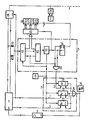
- the figure shows a monitoring device which is connected to a central station.
- the central station 1 is connected to the transmission line 3 via the modem 10.
- the transmission line 3 connects the central station 1 to the substations and possibly to further central stations, of which only the substation 2 is shown with its modem 20.
- the telecontrol telegrams transmitted from the central station 1 to the modem 10 or from the modem 10 to the central station 1 are fed to the monitoring device 5 via the decoupling diodes 61, 62.
- the monitoring device 5 evaluates the data stream.
- the arrangement 51 contained therein which essentially consists of a shift register which can be controlled by the clock generator 6, receives the pulse telegrams and, after a serial-parallel conversion, forwards them on its output bus byte by byte to the device 52 for synchronous character evaluation. If the device 52 recognizes a synchronous character, it releases the control device 53.
- the control device 53 which is connected to the clock generator 6, starts counting the clock pulses from the time of the release and, when a predetermined number of clock pulses is reached, outputs a strobe pulse as a logic “1” to the control circuit 42.
- the drive circuit 42 the is connected to the arrangement 51 via a seven bit wide address bus, is caused by the strobe to adopt the binary coded address.
- the control circuit 42 is used to control the device 41 for numerical display. It contains an address memory and one or more encoders, with the aid of which the control signals required for controlling the device 41 for numerical display are obtained from the binary-coded address information. In an intermediate stage, the address is preferably first converted into the BCD code and then subsequently into the control signals customary for controlling 7-segment display elements.
- the device 41 for numerical display contains a display element which serves to display a decimal point. This display element is controlled separately via the D flip-flop 54.
- This D flip-flop 54 is connected to the output of the control device 53 with its clock input and to a connection of the output of the arrangement 51 with its D input.
- the telecontrol telegrams on which the exemplary embodiment is based are composed of several bytes each with 8 bits.
- the telecontrol telegram begins with a synchronous byte.
- Another byte serves as an address byte and consists of a so-called Z-bit, which serves as a differentiation criterion, and seven address bits.
- the D flip-flop 54 is caused by the strobe pulse of the control device 53 to take over the Z bit and appears at the output of the D flip-flop as a control signal for the additional character of the device 41 a stored central station criterion Z 'as a logical "1".
- the monitoring device 5, the clock generator 6 and the drive circuit 42 may be of a small microcomputer system are constructed in particular with the aid.
- the monitoring arrangement 7 contains the counters 71, 72 and 73, which are each connected to the clock generator 6 with a clock input. The advancement by the clock is blocked when the counter end position is reached in that the output of the counter is connected to an enable input E.
- the outputs of the counters 71, 72 and 73 are also routed to the inputs of the triple-OR element 74, the output of which is routed both to the display device 75 and via the automatic start device 9 to the reset input R of the central station 1.
- the alarm signals of the counters 71, 72, 73 can be displayed individually or only in part, or can be fed to the automatic start.
- the counters 71, 72 and 73 designed as binary counters are reset in different ways.
- the counter 71 is connected with its reset input R to the output of the AND gate 55, which has one input together with the D input of the D flip-flop 54 at a connection of the output of the arrangement 51 and with the other input on Output of the control device 53 is.
- the AND gate 55 queries the Z bit supplied by the arrangement 51 with the aid of the strobe signal emitted by the device 53.
- the counter 71 is therefore reset with each central station telegram. If central station telegrams are missing during a predetermined period of time, the counter 71 reaches its end position and emits an alarm signal to the OR element 74.
- the reset inputs of counters 72 and 73 are dynamic inputs that only respond to positive clock edges.
- the reset input R of the counter 72 is connected to a clock output of the central station 1, which is also connected to a clock input of the modem 10.
- the counter 72 therefore monitors the clock pulse sequence of the central station 1.
- the reset input of the counter 73 is connected to a test pulse output S of the central station 1.
- the device for sequence control of the central station 1 sends monitoring pulses to the test pulse output at regular intervals, even when another central station sends query telegrams to the transmission link and the central station under consideration must therefore remain passive.
- control signal Z ' it controls an optical display for identifying the substation telegrams, which is formed by the decimal point of the device 41 for the numerical display. If the Z bit is missing during a certain period of time, the LED 74 of the display device 75 is activated via the OR gate 74 to emit a central alarm. In addition, this alarm causes the automatic start 9 to restart a microprocessor which is used to control the sequence of the control center 1.
- This automatic start 9 is formed by a clock pulse generator, which emits start pulses at regular time intervals when it is released by an alarm signal via its enable input E.
- the device 41 for digit display makes the addresses of the telegrams running via the telecontrol network and thus the cycle sequence and the telegram exchange visible.
- the telegram addresses of the telecontrol telegrams are displayed on the device 41 for numerical display.
- the decimal point is used to display substation telegrams. The display remains until a new telegram arrives.
- the monitoring device has its own clock supply which is independent of the sequence control of the central station 1 and therefore also recognizes malfunctions of the sequence control which are caused by a faulty clock.
- the own clock supply also makes it possible to use the monitoring device as a service and / or test module in the entire telecontrol network to control the exchange of telegrams.
- the clock generator 6, the device 5 for telegram evaluation and the device 41 with the control circuit 42 are used.
Landscapes
- Physics & Mathematics (AREA)
- General Physics & Mathematics (AREA)
- Selective Calling Equipment (AREA)
- Remote Monitoring And Control Of Power-Distribution Networks (AREA)
- Ultra Sonic Daignosis Equipment (AREA)
Priority Applications (1)
| Application Number | Priority Date | Filing Date | Title |
|---|---|---|---|
| AT81109263T ATE17895T1 (de) | 1981-01-12 | 1981-10-29 | Ueberwachungseinrichtung fuer fernwirkeinrichtungen. |
Applications Claiming Priority (2)
| Application Number | Priority Date | Filing Date | Title |
|---|---|---|---|
| DE19813100683 DE3100683A1 (de) | 1981-01-12 | 1981-01-12 | Ueberwachungseinrichtung fuer fernwirkeinrichtung |
| DE3100683 | 1981-01-12 |
Publications (3)
| Publication Number | Publication Date |
|---|---|
| EP0056099A2 true EP0056099A2 (fr) | 1982-07-21 |
| EP0056099A3 EP0056099A3 (en) | 1983-07-27 |
| EP0056099B1 EP0056099B1 (fr) | 1986-02-05 |
Family
ID=6122468
Family Applications (1)
| Application Number | Title | Priority Date | Filing Date |
|---|---|---|---|
| EP81109263A Expired EP0056099B1 (fr) | 1981-01-12 | 1981-10-29 | Installation de surveillance pour des systèmes de commande à distance |
Country Status (5)
| Country | Link |
|---|---|
| EP (1) | EP0056099B1 (fr) |
| AT (1) | ATE17895T1 (fr) |
| DE (2) | DE3100683A1 (fr) |
| DK (1) | DK8482A (fr) |
| NO (1) | NO155869C (fr) |
Cited By (1)
| Publication number | Priority date | Publication date | Assignee | Title |
|---|---|---|---|---|
| EP0113478A1 (fr) * | 1982-12-24 | 1984-07-18 | Hitachi, Ltd. | Système de sécurité en cas de défaillance pour des systèmes de transmission d'informations |
Family Cites Families (5)
| Publication number | Priority date | Publication date | Assignee | Title |
|---|---|---|---|---|
| DE1566782B1 (de) * | 1967-04-13 | 1970-10-08 | Siemens Ag | Verfahren zum Pruefen von impulsbetriebenen Schaltungen und Schaltungsanordnung zu seiner Durchfuehrung |
| DE2516681C2 (de) * | 1975-04-16 | 1983-08-18 | Siemens AG, 1000 Berlin und 8000 München | Fernwirkeinrichtung |
| DE2806677C2 (de) * | 1978-02-16 | 1983-08-25 | Dieter Dipl.-Phys. Dr. 8031 Eichenau Philipp | Selektiv fernbetätigbares Schaltungssystem |
| DE2928492C2 (de) * | 1979-07-14 | 1985-04-18 | ANT Nachrichtentechnik GmbH, 7150 Backnang | Verfahren zur Überwachung von mehreren, Stationen verbindende Leitungen für Fernwirkmaschennetze |
| DE2929597C2 (de) * | 1979-07-21 | 1984-02-23 | ANT Nachrichtentechnik GmbH, 7150 Backnang | Schaltungsanordnung zum Erkennen eines AIS-Signals und des Ausfalls eines digitalen Signals. |
-
1981
- 1981-01-12 DE DE19813100683 patent/DE3100683A1/de not_active Withdrawn
- 1981-10-29 EP EP81109263A patent/EP0056099B1/fr not_active Expired
- 1981-10-29 AT AT81109263T patent/ATE17895T1/de not_active IP Right Cessation
- 1981-10-29 DE DE8181109263T patent/DE3173740D1/de not_active Expired
-
1982
- 1982-01-08 NO NO820050A patent/NO155869C/no unknown
- 1982-01-11 DK DK8482A patent/DK8482A/da not_active Application Discontinuation
Cited By (1)
| Publication number | Priority date | Publication date | Assignee | Title |
|---|---|---|---|---|
| EP0113478A1 (fr) * | 1982-12-24 | 1984-07-18 | Hitachi, Ltd. | Système de sécurité en cas de défaillance pour des systèmes de transmission d'informations |
Also Published As
| Publication number | Publication date |
|---|---|
| EP0056099A3 (en) | 1983-07-27 |
| DE3173740D1 (en) | 1986-03-20 |
| NO820050L (no) | 1982-07-13 |
| EP0056099B1 (fr) | 1986-02-05 |
| NO155869C (no) | 1987-06-10 |
| ATE17895T1 (de) | 1986-02-15 |
| DK8482A (da) | 1982-07-13 |
| DE3100683A1 (de) | 1982-08-12 |
| NO155869B (no) | 1987-03-02 |
Similar Documents
| Publication | Publication Date | Title |
|---|---|---|
| DE4036639C2 (fr) | ||
| DE2817089A1 (de) | Gefahrenmeldeanlage | |
| DE2539977B2 (de) | Schaltungsanordnung zur Erkennung fehlerhafter Zustände peripherer Einheiten in einer Datenverarbeitungsanlage | |
| DE3431171A1 (de) | Gleisfreimeldeeinrichtung mit achszaehlung | |
| EP0067339A2 (fr) | Méthode et arrangement pour détecter des perturbations dans des systèmes de signalisation de risques, en particulier signalisation d'incendie | |
| DE2749888A1 (de) | Einrichtung zur fehlermeldung | |
| DE3418084A1 (de) | Fernueberwachungseinrichtung fuer die datenuebertragung | |
| DE1812505C3 (de) | Fernwirksystem mit Mehrfachausnutzung eines Übertragungskanals | |
| EP0106985B1 (fr) | Surveillance d'exploitation de voies de transmission numériques | |
| EP0056099B1 (fr) | Installation de surveillance pour des systèmes de commande à distance | |
| CH623948A5 (en) | Data processing system with a multiplicity of on-line stations and use of the system for recording details on manually established telephone connections. | |
| DE3032619C2 (de) | Fernwirkeinrichtung mit wenigstens einer Zentralstation und mit weiteren Stationen | |
| DE10347196B4 (de) | Vorrichtung zur Überprüfung einer Schnittstelle | |
| DE2337290B2 (de) | Überwachungseinrichtung für ein Thyristorventil | |
| EP0060339B1 (fr) | Station pour un dispositif de télécommande | |
| EP0048939B1 (fr) | Dispositif de transmission de signaux comportant des stations équipables facultativement avec des unités d'entrée | |
| DE19921247A1 (de) | Verfahren und Einrichtung zur Überwachung von Softwareapplikationen | |
| DE3202025C2 (de) | Einrichtung zur Betriebskontrolle von Thyristoren eines Hochspannungsventils | |
| DE2908629C2 (de) | Aufrufverfahren für Fernwirksysteme im Gemeinschaftsverkehr | |
| EP0193835A1 (fr) | Dispositif de rassemblement d'informations de surveillance dans des systèmes de transmission | |
| DE3415528C2 (fr) | ||
| EP1430458B1 (fr) | Procede de surveillance d'une installation d'automatisation | |
| DE3141220C2 (fr) | ||
| DE3726573C2 (fr) | ||
| DE2449634A1 (de) | Informations-erfassungssystem |
Legal Events
| Date | Code | Title | Description |
|---|---|---|---|
| PUAI | Public reference made under article 153(3) epc to a published international application that has entered the european phase |
Free format text: ORIGINAL CODE: 0009012 |
|
| 17P | Request for examination filed |
Effective date: 19811029 |
|
| AK | Designated contracting states |
Designated state(s): AT BE CH DE FR GB IT LI SE |
|
| PUAL | Search report despatched |
Free format text: ORIGINAL CODE: 0009013 |
|
| RHK1 | Main classification (correction) |
Ipc: G08C 25/00 |
|
| AK | Designated contracting states |
Designated state(s): AT BE CH DE FR GB IT LI SE |
|
| GRAA | (expected) grant |
Free format text: ORIGINAL CODE: 0009210 |
|
| AK | Designated contracting states |
Designated state(s): AT BE CH DE FR GB IT LI SE |
|
| PG25 | Lapsed in a contracting state [announced via postgrant information from national office to epo] |
Ref country code: LI Free format text: LAPSE BECAUSE OF NON-PAYMENT OF DUE FEES Effective date: 19860205 Ref country code: CH Free format text: LAPSE BECAUSE OF NON-PAYMENT OF DUE FEES Effective date: 19860205 Ref country code: BE Effective date: 19860205 |
|
| REF | Corresponds to: |
Ref document number: 17895 Country of ref document: AT Date of ref document: 19860215 Kind code of ref document: T |
|
| PG25 | Lapsed in a contracting state [announced via postgrant information from national office to epo] |
Ref country code: SE Effective date: 19860228 |
|
| REF | Corresponds to: |
Ref document number: 3173740 Country of ref document: DE Date of ref document: 19860320 |
|
| ITF | It: translation for a ep patent filed | ||
| ET | Fr: translation filed | ||
| PG25 | Lapsed in a contracting state [announced via postgrant information from national office to epo] |
Ref country code: GB Effective date: 19861029 Ref country code: AT Effective date: 19861029 |
|
| PLBI | Opposition filed |
Free format text: ORIGINAL CODE: 0009260 |
|
| 26 | Opposition filed |
Opponent name: STANDARD ELEKTRIK LORENZ AG Effective date: 19861104 |
|
| REG | Reference to a national code |
Ref country code: CH Ref legal event code: PL |
|
| GBPC | Gb: european patent ceased through non-payment of renewal fee | ||
| PGFP | Annual fee paid to national office [announced via postgrant information from national office to epo] |
Ref country code: DE Payment date: 19891219 Year of fee payment: 9 |
|
| PGFP | Annual fee paid to national office [announced via postgrant information from national office to epo] |
Ref country code: FR Payment date: 19901022 Year of fee payment: 10 |
|
| ITTA | It: last paid annual fee | ||
| RDAG | Patent revoked |
Free format text: ORIGINAL CODE: 0009271 |
|
| STAA | Information on the status of an ep patent application or granted ep patent |
Free format text: STATUS: PATENT REVOKED |
|
| 27W | Patent revoked |
Effective date: 19901105 |
|
| GBPR | Gb: patent revoked under art. 102 of the ep convention designating the uk as contracting state | ||
| APAH | Appeal reference modified |
Free format text: ORIGINAL CODE: EPIDOSCREFNO |