EP0056129A2 - Système de mesure de débit comprenant un déphaseur digital et calibrage - Google Patents
Système de mesure de débit comprenant un déphaseur digital et calibrage Download PDFInfo
- Publication number
- EP0056129A2 EP0056129A2 EP81110511A EP81110511A EP0056129A2 EP 0056129 A2 EP0056129 A2 EP 0056129A2 EP 81110511 A EP81110511 A EP 81110511A EP 81110511 A EP81110511 A EP 81110511A EP 0056129 A2 EP0056129 A2 EP 0056129A2
- Authority
- EP
- European Patent Office
- Prior art keywords
- transducer
- phase
- difference
- frequency
- path
- Prior art date
- Legal status (The legal status is an assumption and is not a legal conclusion. Google has not performed a legal analysis and makes no representation as to the accuracy of the status listed.)
- Granted
Links
- 239000012530 fluid Substances 0.000 claims abstract description 47
- 230000006835 compression Effects 0.000 claims abstract description 24
- 238000007906 compression Methods 0.000 claims abstract description 24
- 238000011144 upstream manufacturing Methods 0.000 claims description 10
- 230000010363 phase shift Effects 0.000 claims description 3
- 230000001419 dependent effect Effects 0.000 claims description 2
- 238000005259 measurement Methods 0.000 claims 3
- 230000008859 change Effects 0.000 description 9
- 239000013078 crystal Substances 0.000 description 9
- 230000007246 mechanism Effects 0.000 description 9
- 238000010586 diagram Methods 0.000 description 4
- 230000009977 dual effect Effects 0.000 description 4
- 230000005540 biological transmission Effects 0.000 description 3
- 230000006872 improvement Effects 0.000 description 2
- 238000002604 ultrasonography Methods 0.000 description 2
- 230000003750 conditioning effect Effects 0.000 description 1
- 238000011067 equilibration Methods 0.000 description 1
- 238000010348 incorporation Methods 0.000 description 1
- 239000013618 particulate matter Substances 0.000 description 1
- 230000001360 synchronised effect Effects 0.000 description 1
Images
Classifications
-
- G—PHYSICS
- G01—MEASURING; TESTING
- G01F—MEASURING VOLUME, VOLUME FLOW, MASS FLOW OR LIQUID LEVEL; METERING BY VOLUME
- G01F1/00—Measuring the volume flow or mass flow of fluid or fluent solid material wherein the fluid passes through a meter in a continuous flow
- G01F1/66—Measuring the volume flow or mass flow of fluid or fluent solid material wherein the fluid passes through a meter in a continuous flow by measuring frequency, phase shift or propagation time of electromagnetic or other waves, e.g. using ultrasonic flowmeters
- G01F1/667—Arrangements of transducers for ultrasonic flowmeters; Circuits for operating ultrasonic flowmeters
Definitions
- This invention relates to acoustical flowmeter systems and is particularly directed to an improvement in the acoustical flowmeters of the type described and claimed in the U.S. Patent No. 4,003,252 entitled "Acoustical Wave Flowmeter” by E.J. DeWath which issued Jan 18, 1977 and the flowmeter system of the type described and claimed in the U.S. Patent No. 4,164,865 entitled "Acoustical Wave Flowmeter" by L.G. Hall and R.S. Loveland which issued August 21,1979.
- the invention of DeWath was directed to a flow meter having an unobstructed tubular wall thereby eliminating all impediments to the flow path of the fluid and eliminating all cavities in which debris might collect.
- the advantages of such a configuration is fully set forth in the DeWath Patent.
- To measure flow of a selected fluid in the DeWath flowmeter required a calibration for that particular fluid and required a recalibration if the flow of a different fluid was to be measured since the flowmeter was not responsive to changes in fluid species or densities.
- the Hall and Loveland invention improved the DeWath flowmeter by providing a .flowmeter that measured flow accurately regardless of changes in fluid composition or temperature and by providing a flowmeter with a means for determining a change in velocity of sound of the fluid being measured.
- the Hall and Loveland acoustical wave flowmeter system had two spaced apart crystal transducers in the wall of the flowmeter conduit (sometimes called a cavity) to produce ultrasonic acoustic compressions at selected frequencies in the fluid within the cavity.
- the transducers were alternately switched into a transmit and a receive mode to generate upstream and downstream transmitted and received signals with an automatic means to adjust the transmitted frequencies to compensate for changes in velocity of the acoustic compressions in the fluid caused by changes in fluid composition and temperature.
- the electronic circuitry involved in the Hall and Loveland flowmeter system include means for measuring and storing signals representing the phase difference between the transmitting transducer signal producing the acoustic compressions and the signal produced by the receiving transducer during each of two successive transmit/receive cycles. Circuit means were provided to determine the difference between the signals representing the two successive phase differences wherein the sign of the difference corresponds to the direction of the fluid flow and the magnitude of the difference corresponds to the rate of fluid flow through the flowmeter. Circuit means were also provided to add the two successive phase difference signals together to obtain a signal proportional to the velocity of sound in the fluid moving through the flowmeter. This latter signal indicated the change in composition of the fluid flowing through the meter.
- the Hall and Loveland flowmeter system had a phase lock loop in the receiver/transmitter system which included a phase adjustor comprising two operational amplifiers (3043C) and associated components. This phase adjuster was used during initial calibration to align the transmit and received signals to a 90 0 relative phase difference. Without this phase shifter, this coincidence of signals would not be achievable.
- an object of this invention is to provide a phase shifter which is insensitive to frequency changes in the system and to provide a self calibrator by which the system can be calibrated without the need of an external fluid flow source.
- the flowmeter system which meets the foregoing object comprises means defining a path for confining the flow of a fluid medium therethrough, first and second transducers disposed along said flow path for generating acoustic compression waves in the fluid medium between the transducers, a phase lock loop transmit/receive system including means for automatically adjusting the frequency of the acoustic compression waves to maintain the compression wave length constant in the fluid medium, means for measuring the phase difference of the acoustic compression waves transmitted upstream and downstream relative to that received and for producing sum and difference signals dependent upon the difference between the transmit and receive phases and transmitting said signal to said means for automatically adjusting the frequency of the acoustic compression waves, means for generating signals representing the direction and magnitude of the flow of the fluid medium as well as changes in the velocity of sound in the fluid medium, and a new and improved digital phase shifter and calibrator which is insensitive to frequency for initially aligning and calibrating the system for use.
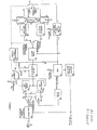
- Figure I illustrates the flowmeter system of the present invention which includes a transducer assembly 10, shown in longitudinal section, which comprises a substanti.ally cylindrical body having a central cylindrical opening, or bore 12, through which a fluid medium flows in both directions, as indicated by the arrows 14.
- transducer assembly 10 shown in longitudinal section, which comprises a substanti.ally cylindrical body having a central cylindrical opening, or bore 12, through which a fluid medium flows in both directions, as indicated by the arrows 14.
- the transducer assembly is made generally in accordance with the description in the U.S. Patent to DeWath, supra, and is provided with spaced apart cylindrical crystal transducers whose inner diameters are substantially coextensive with the cylindrical bore 12 so that the wall is substantially uniform with no obstructions or cavities to provide a place for particulate matter to collect or to provide an impediment for the flow of fluid therethrough.
- the purpose of the transducers is described in the DeWath patent and in the Hall and Loveland patent, supra.
- the two ultrasonic crystal transducers represented by crystals 16 and 18, also identified as CR D and CR U , are alternately each connected to the transmission control circuitry via a switching mechanism 20.
- the other transducer is in the receive mode the output of which in turn is connected via a second switching mechanism 26 to a phase detector 28, a signal integrator 30 and two sample-and-hold circuits 32 and 34, identified as upstream and downstream.
- the outputs of these two sample-and-hold circuits are connected to two operational amplifiers, one identified as a summing amplifier 36 and the other identified as a difference amplifier 38.
- the output of the summing amplifier 36 will indicate the velocity of sound and the output of the difference amplifier will indicate the magnitude and direction of the measured fluid flow.
- the output of the summing amplifier is connected to a loop filter 40 and to a voltage controlled oscillator 42 (VCO) which is connected back to the phase detector 28 and to a phase shifier and square-wave-to-sine wave converter 44.
- the phase shifter and converter 44 output is connected back to the first switching mechanism 20.
- the output of the difference amplifier 38 is connected to the VCO 42 but through a multiplier 46 and a velocity of sound conditioning circuit 48.
- One output of the multiplier is the magnitude and direction of the fluid flow as stated above and the second output represents the relative velocity of sound.
- the circuit 54 alternates transmit and receive functions of the two crystal transducers 16 and 18, alternates the output of the upstream and downstream receivers 22 and 24, operates the integrator 30 between reset, integrate and hold functions and, finally, operates the upstream and downstream sample-and-hold circuits 32 and 34 through a sample, hold, and sample function.
- the ultrasonic crystals 16 and 18 are alternately switched into either the transmit or receive mode by the combinational logic circuit. Thus, while one crystal is receiving, the other crystal is transmitting.
- the phase difference between the transmit signal and the received signal is detected by the phase detector 28.
- the average value is determined for each transmit/receive cycle by the integrator circuit 30 which goes through an integrate, hold and reset mode for each transmit/receive cycle.
- the respective sample/hold circuit for the upstream phase and the downstream phase is ready to accept the new signal (sample mode) as data is available at the integrator output.
- the upstream and downstream sample/hold circuits are updated with new data at the end of each respective transmit/receive cycle and stores (holds) the information during the wait period.
- the stored values are then subtracted with the output indicating the direction and magnitude of the fluid flow.
- the same stored values are added together in the summing amplifier to determine if a common mode change has occurred in the fluid medium.
- a common mode change is caused by a change in the velocity of the ultrasound which, in turn, may be due to either temperature or fluid species change.
- VCO voltage controlled oscillator
- the switching mechanism 20 in this disclosure is acutally a combination of high speed transistorized switches comprised of transistors Q1 thru 08 controlled from the clock source by pulses X,Y,Q3 and Q3 applied to their respective inputs, switching meachanism 26 are transistors Q9 and Q10 with pulses A & B applied to their respective inputs, etc.
- Other switching mechanisms exist in the circuitry of the patent through the operation of the clock source but otherwise the block diagrams correspond to the patented circuitry. It is understood that the other switching mechanisms were shown here to illustrate the operation of the circuitry in the block diagram only.
- this invention improves the patented system by providing a phase shifter which is insensitive to frequency changes in the system and providing a means for calibrating a system without the need of an external source of fluid.
- Figure 2 illustrates. the patented phase adjuster and to Figure I where the phase adjuster is represented .
- the two 8043C operational amplifiers with adjustment resistors being operative to adjust the phase of the signal during calibration of the flowmeter and are preferably adjusted to a selected transmission frequency with no fluid flow through the transducer assembly 10.
- the phase adjuster of the patented circuitry changed as a function of frequency which produced an error such that the entire phase lock loop made an adjustment as if this error was a phase error due to a change in density, wherein, in fact, it was only an error in the phase adjusting circuitry.
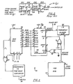
- FIG. 3 there is shown a digital phase shifter and calibrator 70 which is insensitive to frequency changes and which may be used to calibrate the system.
- the digital phase shift generator is a dual 4 bit shift register 72 (MC14015 BCP) connected to the VCO 42 through a pair of exclusive OR gates 74 & 76 (MC 14070BCP).
- the pair of exclusive OR circuits provide clock signals to each half of the dual two shift register which are 180° out of phase thereby causing each register to shift alternately.
- the outputs of the shift register 72 are connected to an 8 channel multiplexer 78 (MC1405IBCP) which, in turn, is connected to the square-wave-to-sine wave converter 80.
- Square wave-to-sine wave converter 80 in this figure is shown and identified separately for sake of clarity although shown as part of the phase shifter in Figure 1.
- the signal of 400 kilohertz, from the VCO is applied to the input pin 9 of the dual up counter 82 which divides the VCO frequency by 8 to obtain the transmit frequency.
- the dual shift register advances the input signal. to the next logic storage unit at each clock pulse which is eight times the transmit frequency.
- the input to the "B" shift register is an output of the "A” shift register which is displaced by 22.5° relative to the input to the "A” shift register. This enables shifting of transmit signal to take place essentially every 22 1 ⁇ 2 degrees.
- the net result is to have the eight outputs from the shift register Q1A, Q2A...Q4A, Q4B which are 22Yz degrees apart.
- phase shifter circuitry may be shifted from 0° to 360° in 221 ⁇ 2° increments.
- the phase shift thru this circuitry may be chosen by a switching sequence of switches SI-S6 applied to logic pins A,B, C and exclusive OR circuit 84 , which command a certain signal phase to appear at the output and subsequently transmitted out.
- the calibrate mode may be enabled which causes the phase of the transmitted signal to change from plus 90° to minus 90° for alternate transmit cycles thereby simulating that which would happen with a calibrated flow.
- the phase of this signal can be changed so that the output either represents a plus '/2 of full scale (liters per second) or a minus 1/2 of full scale (liters per second)
Landscapes
- Physics & Mathematics (AREA)
- Electromagnetism (AREA)
- Fluid Mechanics (AREA)
- General Physics & Mathematics (AREA)
- Measuring Volume Flow (AREA)
Applications Claiming Priority (2)
| Application Number | Priority Date | Filing Date | Title |
|---|---|---|---|
| US06/224,723 US4372166A (en) | 1981-01-13 | 1981-01-13 | Flowmeter system with digital phase shifter and calibration |
| US224723 | 1981-01-13 |
Publications (3)
| Publication Number | Publication Date |
|---|---|
| EP0056129A2 true EP0056129A2 (fr) | 1982-07-21 |
| EP0056129A3 EP0056129A3 (en) | 1983-07-06 |
| EP0056129B1 EP0056129B1 (fr) | 1987-03-25 |
Family
ID=22841896
Family Applications (1)
| Application Number | Title | Priority Date | Filing Date |
|---|---|---|---|
| EP81110511A Expired EP0056129B1 (fr) | 1981-01-13 | 1981-12-16 | Système de mesure de débit comprenant un déphaseur digital et calibrage |
Country Status (4)
| Country | Link |
|---|---|
| US (1) | US4372166A (fr) |
| EP (1) | EP0056129B1 (fr) |
| JP (1) | JPS57136122A (fr) |
| DE (1) | DE3176037D1 (fr) |
Cited By (3)
| Publication number | Priority date | Publication date | Assignee | Title |
|---|---|---|---|---|
| EP0059797A3 (en) * | 1981-01-13 | 1984-04-18 | The Perkin-Elmer Corporation | Acoustic flowmeter with phase locked loop |
| DE19625667A1 (de) * | 1996-06-26 | 1998-01-02 | Siemens Ag | Verfahren zum Selbsttest einer Einrichtung zur Ultraschall-Laufzeitmessung sowie Einrichtung zur Durchführung des Verfahrens |
| CN113884164A (zh) * | 2021-12-06 | 2022-01-04 | 成都千嘉科技有限公司 | 超声波燃气表的自适应标定方法 |
Families Citing this family (17)
| Publication number | Priority date | Publication date | Assignee | Title |
|---|---|---|---|---|
| US4509372A (en) * | 1983-04-04 | 1985-04-09 | The Perkin-Elmer Corporation | Acoustical wave flowmeter with increased density capability |
| US4527433A (en) * | 1983-10-25 | 1985-07-09 | General Motors Corporation | Method and apparatus for measuring fluid flow |
| US4527432A (en) * | 1983-11-07 | 1985-07-09 | General Motors Corporation | Dual frequency acoustic fluid flow method and apparatus |
| US4542470A (en) * | 1984-07-16 | 1985-09-17 | Spartanics, Ltd. | Frequency determining and lock-on system |
| US4831866A (en) * | 1987-11-09 | 1989-05-23 | Tokheim Corporation | Automatic meter proving and calibration system |
| US4896540A (en) * | 1988-04-08 | 1990-01-30 | Parthasarathy Shakkottai | Aeroacoustic flowmeter |
| US5000039A (en) * | 1989-11-21 | 1991-03-19 | Siemens-Bendix Automotive Electronics L.P. | Mass air flow integrator |
| US4989446A (en) * | 1990-01-23 | 1991-02-05 | Dynatek Laboratories, Inc. | Ultrasound calibrator |
| DK56593A (da) * | 1992-08-25 | 1994-02-26 | Kamstrup Metro As | Strømningsmåler |
| US5604684A (en) * | 1993-12-30 | 1997-02-18 | Juntunen; Robert D. | Embedded programmable sensor calibration method |
| FR2739185B1 (fr) * | 1995-09-25 | 1997-11-14 | Schlumberger Ind Sa | Procede de mesure acoustique d'un debit de fluide |
| US5918281A (en) * | 1996-05-28 | 1999-06-29 | Nabulsi; Haz | Personal speedometer |
| US5728947A (en) * | 1996-06-12 | 1998-03-17 | Asahi/America, Inc. | Ultrasonic vortex flowmeter having clamp-on housing |
| DE10161071A1 (de) * | 2001-12-12 | 2003-06-18 | Endress & Hauser Gmbh & Co Kg | Feldgeräteelektronik mit einer Sensoreinheit für die Prozessmesstechnik |
| US20080201898A1 (en) * | 2007-02-23 | 2008-08-28 | Charbonneau Gary P | Self-cleaning filter arrangement with activation signal for floor care apparatus |
| TWI400444B (zh) * | 2010-08-13 | 2013-07-01 | Tatung Co | 超音波相位偏移之偵測裝置 |
| US8494932B2 (en) * | 2011-03-18 | 2013-07-23 | International Business Machines Corporation | Fluid flow measurement system |
Family Cites Families (5)
| Publication number | Priority date | Publication date | Assignee | Title |
|---|---|---|---|---|
| DE2114373C3 (de) * | 1971-03-25 | 1980-04-17 | Fried. Krupp Gmbh, 4300 Essen | Schaltanordnung zum Bilden von Gruppensignalen in der Peiltechnik unter Verwendung von Verzögerungsschaltungen |
| US4003252A (en) * | 1974-08-16 | 1977-01-18 | The Institutes Of Medical Sciences | Acoustical wave flowmeter |
| DE2517117A1 (de) * | 1975-04-18 | 1976-10-28 | Standard Elektrik Lorenz Ag | Anordnung zum bestimmen der stroemungsgeschwindigkeit von fluessigkeiten und gasen |
| US4101881A (en) * | 1976-03-15 | 1978-07-18 | Hybrid Systems Corporation | Multiple state responsive delta-sigma converter and delay line |
| US4164865A (en) * | 1977-02-22 | 1979-08-21 | The Perkin-Elmer Corporation | Acoustical wave flowmeter |
-
1981
- 1981-01-13 US US06/224,723 patent/US4372166A/en not_active Expired - Fee Related
- 1981-12-16 EP EP81110511A patent/EP0056129B1/fr not_active Expired
- 1981-12-16 DE DE8181110511T patent/DE3176037D1/de not_active Expired
-
1982
- 1982-01-13 JP JP57002912A patent/JPS57136122A/ja active Pending
Cited By (4)
| Publication number | Priority date | Publication date | Assignee | Title |
|---|---|---|---|---|
| EP0059797A3 (en) * | 1981-01-13 | 1984-04-18 | The Perkin-Elmer Corporation | Acoustic flowmeter with phase locked loop |
| DE19625667A1 (de) * | 1996-06-26 | 1998-01-02 | Siemens Ag | Verfahren zum Selbsttest einer Einrichtung zur Ultraschall-Laufzeitmessung sowie Einrichtung zur Durchführung des Verfahrens |
| CN113884164A (zh) * | 2021-12-06 | 2022-01-04 | 成都千嘉科技有限公司 | 超声波燃气表的自适应标定方法 |
| CN113884164B (zh) * | 2021-12-06 | 2022-02-22 | 成都千嘉科技有限公司 | 超声波燃气表的自适应标定方法 |
Also Published As
| Publication number | Publication date |
|---|---|
| EP0056129B1 (fr) | 1987-03-25 |
| DE3176037D1 (en) | 1987-04-30 |
| EP0056129A3 (en) | 1983-07-06 |
| JPS57136122A (en) | 1982-08-23 |
| US4372166A (en) | 1983-02-08 |
Similar Documents
| Publication | Publication Date | Title |
|---|---|---|
| US4372166A (en) | Flowmeter system with digital phase shifter and calibration | |
| CA1157935A (fr) | Debitmetre ultrasonique | |
| US3818757A (en) | Dual path ultrasonic fluid flow metering system and method | |
| US4527433A (en) | Method and apparatus for measuring fluid flow | |
| US3720105A (en) | Acoustic flowmeter | |
| US3780577A (en) | Ultrasonic fluid speed of sound and flow meter apparatus and method | |
| US4011753A (en) | Method and device for measuring the flow velocity of media by means of ultrasound | |
| IE42188B1 (en) | Method and apparatus for monitoring the flow of liquid andthe like | |
| JP4538163B2 (ja) | 流速測定方法及び流速測定装置並びに流量測定方法及び流量測定装置 | |
| JPS6048690B2 (ja) | 流れる媒体の流速を超音波測定する装置 | |
| US4509372A (en) | Acoustical wave flowmeter with increased density capability | |
| US3420102A (en) | Acoustic fluid metering device | |
| US4345479A (en) | Flowmeter system with synchronous clock for generation of timing signals | |
| US2758663A (en) | Sound velocity measuring system | |
| US4372167A (en) | Flowmeter system with improved loop gain | |
| EP0056137B1 (fr) | Système de mesure de débit à amélioration d'équilibrage pour l'énergie ultrasonore | |
| US4478088A (en) | Flowmeter system with ultrasonic energy improvement in equilibration | |
| US4611496A (en) | Ultrasonic flow meter | |
| DK0762086T3 (da) | Fremgangsmåde til ultralyd-måling af gennemstrømningsmængder af strømmende fluider | |
| EP0056135A2 (fr) | Système de mesure de débit à étendue de mesure améliorée | |
| US2923155A (en) | Ultrasonic flowmeter | |
| US4372168A (en) | Flowmeter | |
| JPS6261893B2 (fr) | ||
| US4203322A (en) | Apparatus for the ultrasonic measurement of the flow velocity of fluent media | |
| US3097526A (en) | fischbacher |
Legal Events
| Date | Code | Title | Description |
|---|---|---|---|
| PUAI | Public reference made under article 153(3) epc to a published international application that has entered the european phase |
Free format text: ORIGINAL CODE: 0009012 |
|
| AK | Designated contracting states |
Designated state(s): DE FR GB |
|
| PUAL | Search report despatched |
Free format text: ORIGINAL CODE: 0009013 |
|
| AK | Designated contracting states |
Designated state(s): DE FR GB |
|
| 17P | Request for examination filed |
Effective date: 19840104 |
|
| GRAA | (expected) grant |
Free format text: ORIGINAL CODE: 0009210 |
|
| AK | Designated contracting states |
Kind code of ref document: B1 Designated state(s): DE FR GB |
|
| REF | Corresponds to: |
Ref document number: 3176037 Country of ref document: DE Date of ref document: 19870430 |
|
| ET | Fr: translation filed | ||
| PLBE | No opposition filed within time limit |
Free format text: ORIGINAL CODE: 0009261 |
|
| STAA | Information on the status of an ep patent application or granted ep patent |
Free format text: STATUS: NO OPPOSITION FILED WITHIN TIME LIMIT |
|
| 26N | No opposition filed | ||
| PG25 | Lapsed in a contracting state [announced via postgrant information from national office to epo] |
Ref country code: GB Effective date: 19891216 |
|
| GBPC | Gb: european patent ceased through non-payment of renewal fee | ||
| PG25 | Lapsed in a contracting state [announced via postgrant information from national office to epo] |
Ref country code: FR Effective date: 19900831 |
|
| PG25 | Lapsed in a contracting state [announced via postgrant information from national office to epo] |
Ref country code: DE Effective date: 19900901 |
|
| REG | Reference to a national code |
Ref country code: FR Ref legal event code: ST |