EP0056256A2 - Ferme-porte - Google Patents
Ferme-porte Download PDFInfo
- Publication number
- EP0056256A2 EP0056256A2 EP82100089A EP82100089A EP0056256A2 EP 0056256 A2 EP0056256 A2 EP 0056256A2 EP 82100089 A EP82100089 A EP 82100089A EP 82100089 A EP82100089 A EP 82100089A EP 0056256 A2 EP0056256 A2 EP 0056256A2
- Authority
- EP
- European Patent Office
- Prior art keywords
- pinion
- door
- teeth
- rack
- door closer
- Prior art date
- Legal status (The legal status is an assumption and is not a legal conclusion. Google has not performed a legal analysis and makes no representation as to the accuracy of the status listed.)
- Withdrawn
Links
Images
Classifications
-
- E—FIXED CONSTRUCTIONS
- E05—LOCKS; KEYS; WINDOW OR DOOR FITTINGS; SAFES
- E05F—DEVICES FOR MOVING WINGS INTO OPEN OR CLOSED POSITION; CHECKS FOR WINGS; WING FITTINGS NOT OTHERWISE PROVIDED FOR, CONCERNED WITH THE FUNCTIONING OF THE WING
- E05F3/00—Closers or openers with braking devices, e.g. checks; Construction of pneumatic or liquid braking devices
- E05F3/04—Closers or openers with braking devices, e.g. checks; Construction of pneumatic or liquid braking devices with liquid piston brakes
- E05F3/10—Closers or openers with braking devices, e.g. checks; Construction of pneumatic or liquid braking devices with liquid piston brakes with a spring, other than a torsion spring, and a piston, the axes of which are the same or lie in the same direction
- E05F3/102—Closers or openers with braking devices, e.g. checks; Construction of pneumatic or liquid braking devices with liquid piston brakes with a spring, other than a torsion spring, and a piston, the axes of which are the same or lie in the same direction with rack-and-pinion transmission between driving shaft and piston within the closer housing
-
- E—FIXED CONSTRUCTIONS
- E05—LOCKS; KEYS; WINDOW OR DOOR FITTINGS; SAFES
- E05F—DEVICES FOR MOVING WINGS INTO OPEN OR CLOSED POSITION; CHECKS FOR WINGS; WING FITTINGS NOT OTHERWISE PROVIDED FOR, CONCERNED WITH THE FUNCTIONING OF THE WING
- E05F3/00—Closers or openers with braking devices, e.g. checks; Construction of pneumatic or liquid braking devices
- E05F3/22—Additional arrangements for closers, e.g. for holding the wing in opened or other position
- E05F3/225—Additional arrangements for closers, e.g. for holding the wing in opened or other position mounted at the bottom of wings, e.g. details related to seals, covers, connections to the wings, embedding in the floor
- E05F3/226—Additional arrangements for closers, e.g. for holding the wing in opened or other position mounted at the bottom of wings, e.g. details related to seals, covers, connections to the wings, embedding in the floor with means to adjust the closed position of the wing
-
- E—FIXED CONSTRUCTIONS
- E05—LOCKS; KEYS; WINDOW OR DOOR FITTINGS; SAFES
- E05Y—INDEXING SCHEME ASSOCIATED WITH SUBCLASSES E05D AND E05F, RELATING TO CONSTRUCTION ELEMENTS, ELECTRIC CONTROL, POWER SUPPLY, POWER SIGNAL OR TRANSMISSION, USER INTERFACES, MOUNTING OR COUPLING, DETAILS, ACCESSORIES, AUXILIARY OPERATIONS NOT OTHERWISE PROVIDED FOR, APPLICATION THEREOF
- E05Y2201/00—Constructional elements; Accessories therefor
- E05Y2201/20—Brakes; Disengaging means; Holders; Stops; Valves; Accessories therefor
-
- E—FIXED CONSTRUCTIONS
- E05—LOCKS; KEYS; WINDOW OR DOOR FITTINGS; SAFES
- E05Y—INDEXING SCHEME ASSOCIATED WITH SUBCLASSES E05D AND E05F, RELATING TO CONSTRUCTION ELEMENTS, ELECTRIC CONTROL, POWER SUPPLY, POWER SIGNAL OR TRANSMISSION, USER INTERFACES, MOUNTING OR COUPLING, DETAILS, ACCESSORIES, AUXILIARY OPERATIONS NOT OTHERWISE PROVIDED FOR, APPLICATION THEREOF
- E05Y2201/00—Constructional elements; Accessories therefor
- E05Y2201/20—Brakes; Disengaging means; Holders; Stops; Valves; Accessories therefor
- E05Y2201/23—Actuation thereof
- E05Y2201/232—Actuation thereof by automatically acting means
-
- E—FIXED CONSTRUCTIONS
- E05—LOCKS; KEYS; WINDOW OR DOOR FITTINGS; SAFES
- E05Y—INDEXING SCHEME ASSOCIATED WITH SUBCLASSES E05D AND E05F, RELATING TO CONSTRUCTION ELEMENTS, ELECTRIC CONTROL, POWER SUPPLY, POWER SIGNAL OR TRANSMISSION, USER INTERFACES, MOUNTING OR COUPLING, DETAILS, ACCESSORIES, AUXILIARY OPERATIONS NOT OTHERWISE PROVIDED FOR, APPLICATION THEREOF
- E05Y2201/00—Constructional elements; Accessories therefor
- E05Y2201/40—Motors; Magnets; Springs; Weights; Accessories therefor
- E05Y2201/43—Motors
- E05Y2201/448—Fluid motors; Details thereof
- E05Y2201/458—Valves
-
- E—FIXED CONSTRUCTIONS
- E05—LOCKS; KEYS; WINDOW OR DOOR FITTINGS; SAFES
- E05Y—INDEXING SCHEME ASSOCIATED WITH SUBCLASSES E05D AND E05F, RELATING TO CONSTRUCTION ELEMENTS, ELECTRIC CONTROL, POWER SUPPLY, POWER SIGNAL OR TRANSMISSION, USER INTERFACES, MOUNTING OR COUPLING, DETAILS, ACCESSORIES, AUXILIARY OPERATIONS NOT OTHERWISE PROVIDED FOR, APPLICATION THEREOF
- E05Y2900/00—Application of doors, windows, wings or fittings thereof
- E05Y2900/10—Application of doors, windows, wings or fittings thereof for buildings or parts thereof
- E05Y2900/13—Type of wing
- E05Y2900/132—Doors
Definitions
- the present invention relates to door closers, i.e. to those devices that can be secured to a door, window or the like-and cause them to close automatically.
- the main object to be solved in this particular field by the device of the invention is to provide a door closer of sufficient power and yet of such a small size as to be installed and concealed within one of the usual sections or shapes forming the wing of a door, bearing in mind that the door can be opened in either direction of rotation and, therefore, that the door closer must be of the double-acting type.
- the device uses a mechanism comprising a pinion that, depending upon the direction of rotation of the door, must mesh with no backlash with either one of a pair of parallel and opposite racks, that is a mechanism capable of solving the following consequential problem:
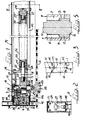
- the door closer of the invention comprises a body 1 of parallelepiped or any other suitable shape and of such size as to be accommodated within one of the transverse sections that usually from a door wing, as best described hereinafter.
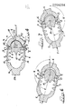
- a chamber 2 formed in the body 1 there is a chamber 2 at the interior of which a double rack of annular configuration in plan view (see Figure 4) is guided and can move longitudinally.
- the two racks 3 and 4 have the same shape and are parallely opposite to each other and are connected to each other.at their ends by means of suitably merging portion 5 and 6.
- the racks have the same number of teeth, and the teeth of one rack are perfectly in line and in opposite relation to the teeth of the other.
- the teeth 7, 8, 9 of rack 3 and the teeth 10, 11, 12 of rack 4 are of reduced length, that is they extend on the body of each rack only for'a fraction of its height, and these teeth are all located at the same level, as shown for example in Figure 5 where these teeth are located on the upper ° portion of said racks.
- the teeth 13 and 14 of the two racks are of normal or entire length as shown in Figure 5.
- a toothed sector 15 having the same number of teeth as the recesses in the toothing of each rack is arranged between the two racks, and said teeth are located in a sector of circumference having an amplitude of 180° or less.
- the configuration and size of the pinion 15 are such as to permit the pinion to mesh with no backlash and roll on either racks 3-4 depending on the direction of rotation imparted'to the latter, as explained below.
- the first and the last tooth of pinion 15, indicated by numerals 16 and 17, respectively are both contacting the body of the racks 3 and 4 (see below), which are urged longitudinally as indicated by the arrow F, by suitable resilient means which will be described hereinafter.
- the teeth 16, 17 of said pinion 15 are of reduced length with respect to the intermediate teeth, and said teeth 16, 17 are located in such a position to avoid any interference with the reduced teeth of the racks 3 and 4 (see also Figure 5).
- the racks and pinion 15 are made of a suitable material and are suitably treated to withstand all mechanical stresses exerted thereagainst during the normal operation of the door closer.
- the pinion 15 is provided with an integral shaft 18 which is rotatably supported by the body l'through a pair of bushings 19-20 and respective bearings.
- the end portion 118 of the shaft 18 sealingly projects from the bushing 20 through an annular sealing ring 21; and said end portion is formed with at least one flattered portion 218 or any other suitable means to be fixedly connected to a member which will be discussed hereinafter in connection with the arrangement of the door-closer in the operating position.
- stub member 105 Formed at the end 5 of the double rack there is an integral stub member 105, to which there is a rod 22 perpendicular to said shaft 18 and projecting with clearance through a bore 23 of a cover 24 that sealingly closes said chamber 2 with the aid of a gasket 25.
- a tubular member 26 On a stub member 124 of said cover 24 there is sealingly secured, by screw connection, a tubular member 26 which is sealingly closed at the opposite end by a plug 27 provided with an inverted "U" support 28, having the purpose set forth hereinafter.
- the rod 22 co-axially projects into said tubular member 26 with a reduced portion 122 supporting a spring-bearing disc 29'.
- a similar spring-bearing disc 29" with an axial centering pin is provided within said tubular member 26 adjacent said plug 27. Between the discs 29' and 29 ' ' there is mounted a compression-loaded assembly 30 comprising the springs that urge the racks 3-4 in the direction indicated by the arrow F ( Figure 4). Opposed to the stub member 105 and co-axial with the rod 22 at the other end 6 of the double rack is integrally formed a piston 106 of round cross-section, sealingly slidable axially in a corresponding bore formed in the body 1 and closed at the outer end by a plug 31.
- the compression chamber 32 the volume of which changes as a function of the axial movement of the piston 106, communicates permanently with the chamber 2 through a duct 33 and a variable restrictor 34, preferably of thermostatic type, suitably mounted in the body 1.
- a unidirectional valve 35 permitting the free communication between the chambers 2 and 32, but preventing automatically any communication in the contrary direction.
- the regulating section of the door closer is completed by a hole 36 formed in the body 1 and communicating with the chamber 32 through an invariable port of the restrictor 34.
- said hole 36 communicates with a hole 37 formed in said piston and in open communication with the chamber 2.
- the chambers 2, 32 and tubular member 26 are filled with oil or any other suitable liquid.
- the door closer described above is arranged preferably at the interior of the lower transverse channel section Pl of the door wing.
- Vl and V2 indicate the screws usually securing the section member Pl to the section member P2 of the door wing.
- the sections Pl and P2 are to be submitted to the following operations.
- An opening 38 is formed in the back concealed wall of the section member P2, in the region abutted by the section member P1, while the front wall of P2, opposite said opening 38, is formed with a hole 39 and a number of further holes for the insertion of screws (see below).
- a length of the channel section P1, in continuation of the channel P2, is formed with a longitudinal bottom opening 40.
- the door-closer is introduced into the channel section Pl through the opening 40, whereafter the end of the body 1 is introduced into the opening 38 to abut the outer wall of the channel P2.
- the body 1 is then secured to the latter wall by screws 42 (see Figure 3).
- the restrictor 34 can be regulated in order to change the braking mode of the door closer.
- said support 28 is fixed to the latter wall, so that the device can be fixedly connected to the door wing. Thereafter, the door will be arranged in place.
- the upper transverse channel is provided with a hinge pivot co-axial with said shaft 18, whose end portion 118 is keyed to a bushing 43 secured in the floor Z.
- the door in the final portion of its closing rotation, will be damped to a' lesser degree in the last portion of its closing stroke, so that the door can move to a perfect closing position, even if spring latches or locking bolts of a look are provided.
Landscapes
- Gears, Cams (AREA)
Applications Claiming Priority (2)
| Application Number | Priority Date | Filing Date | Title |
|---|---|---|---|
| IT03307/81A IT1145005B (it) | 1981-01-14 | 1981-01-14 | Chiudiporta a doppio effetto, particolarmente adatto per l'installazione all'interno della normale anta di una porta o di un altro serramento |
| IT330781 | 1981-01-14 |
Publications (2)
| Publication Number | Publication Date |
|---|---|
| EP0056256A2 true EP0056256A2 (fr) | 1982-07-21 |
| EP0056256A3 EP0056256A3 (fr) | 1983-02-23 |
Family
ID=11104667
Family Applications (1)
| Application Number | Title | Priority Date | Filing Date |
|---|---|---|---|
| EP82100089A Withdrawn EP0056256A3 (fr) | 1981-01-14 | 1982-01-08 | Ferme-porte |
Country Status (2)
| Country | Link |
|---|---|
| EP (1) | EP0056256A3 (fr) |
| IT (1) | IT1145005B (fr) |
Cited By (6)
| Publication number | Priority date | Publication date | Assignee | Title |
|---|---|---|---|---|
| DE3638353A1 (de) * | 1985-07-05 | 1987-10-29 | Geze Gmbh | Tuerschliesser |
| US4744125A (en) * | 1985-07-05 | 1988-05-17 | Geze Gmbh | Door closer transmission including an eccentric pinion |
| US4763385A (en) * | 1985-07-05 | 1988-08-16 | Geze Gmbh | Door closure transmission utilizing an eccentric pinion |
| WO2002064932A1 (fr) | 2001-02-13 | 2002-08-22 | Dorma Gmbh + Co. Kg | Entrainement electromecanique de battant articule |
| DE10107046C2 (de) * | 2001-02-13 | 2003-05-28 | Dorma Gmbh & Co Kg | Gleitschienenschließer |
| DE10107050C2 (de) * | 2001-02-13 | 2003-07-03 | Dorma Gmbh & Co Kg | Hydraulischer Drehflügelantrieb |
Family Cites Families (2)
| Publication number | Priority date | Publication date | Assignee | Title |
|---|---|---|---|---|
| GB663592A (en) * | 1949-07-22 | 1951-12-27 | S B & N Ltd | Improvements in or relating to door closing or controlling means |
| GB684207A (en) * | 1950-02-14 | 1952-12-10 | Ellison Bronze Company Inc | Double acting door check and spring combination |
-
1981
- 1981-01-14 IT IT03307/81A patent/IT1145005B/it active
-
1982
- 1982-01-08 EP EP82100089A patent/EP0056256A3/fr not_active Withdrawn
Cited By (7)
| Publication number | Priority date | Publication date | Assignee | Title |
|---|---|---|---|---|
| DE3638353A1 (de) * | 1985-07-05 | 1987-10-29 | Geze Gmbh | Tuerschliesser |
| US4744125A (en) * | 1985-07-05 | 1988-05-17 | Geze Gmbh | Door closer transmission including an eccentric pinion |
| US4763385A (en) * | 1985-07-05 | 1988-08-16 | Geze Gmbh | Door closure transmission utilizing an eccentric pinion |
| WO2002064932A1 (fr) | 2001-02-13 | 2002-08-22 | Dorma Gmbh + Co. Kg | Entrainement electromecanique de battant articule |
| DE10107046C2 (de) * | 2001-02-13 | 2003-05-28 | Dorma Gmbh & Co Kg | Gleitschienenschließer |
| DE10107051C2 (de) * | 2001-02-13 | 2003-06-26 | Dorma Gmbh & Co Kg | Elektromechanischer Drehflügelantrieb |
| DE10107050C2 (de) * | 2001-02-13 | 2003-07-03 | Dorma Gmbh & Co Kg | Hydraulischer Drehflügelantrieb |
Also Published As
| Publication number | Publication date |
|---|---|
| EP0056256A3 (fr) | 1983-02-23 |
| IT8103307A0 (it) | 1981-01-14 |
| IT1145005B (it) | 1986-11-05 |
Similar Documents
| Publication | Publication Date | Title |
|---|---|---|
| EP0544254B1 (fr) | Méthode pour positionner une porte pivotante dans une position déterminée et une came et son mécanisme suiveur utilisés dans cette méthode | |
| US3246362A (en) | Door closer | |
| US5187835A (en) | Door closer with rack and pinion, spring, and spring mounting plate | |
| US5291630A (en) | Damper and method of controlling a door | |
| US20130227814A1 (en) | Door closer, particularly for glass doors | |
| US4763385A (en) | Door closure transmission utilizing an eccentric pinion | |
| EP0458454B1 (fr) | Ferme-porte | |
| US8875345B2 (en) | Hinge | |
| US4386446A (en) | Door closer | |
| US5195210A (en) | Hydraulic door hinge | |
| EP0056256A2 (fr) | Ferme-porte | |
| US5050268A (en) | Door closer with back checking means | |
| EP0856628B1 (fr) | Ferme-porte | |
| US4190925A (en) | Door-closer and hinge combination | |
| DE10083949B4 (de) | Rotationskolbenversteller | |
| US1921314A (en) | Door closer and check | |
| CN201326333Y (zh) | 一种铰链 | |
| DE102012210814B4 (de) | Antrieb zum Öffnen und/oder Schließen eines beweglichen Flügels einer Tür oder eines Fensters sowie Verfahren zum Betrieb dieses Antriebs | |
| EP3798398A1 (fr) | Dispositif de charnière pour porte rotative | |
| EP0298231A1 (fr) | Ferme-porte | |
| DE3631113C1 (de) | Hydraulischer Daempfungszylinder fuer Kipprueckschlagklappen | |
| RU196446U1 (ru) | Гидравлический доводчик двери | |
| US2158417A (en) | Closing and checking unit | |
| DE102011018734A1 (de) | Drehflügeltürbetätiger | |
| DE2952488A1 (de) | Einrichtung zum beeinflussen des einspritzzeitpunktes bei einem dieselmotor |
Legal Events
| Date | Code | Title | Description |
|---|---|---|---|
| PUAI | Public reference made under article 153(3) epc to a published international application that has entered the european phase |
Free format text: ORIGINAL CODE: 0009012 |
|
| AK | Designated contracting states |
Designated state(s): AT BE CH DE FR GB LU NL SE |
|
| PUAL | Search report despatched |
Free format text: ORIGINAL CODE: 0009013 |
|
| AK | Designated contracting states |
Designated state(s): AT BE CH DE FR GB LI LU NL SE |
|
| STAA | Information on the status of an ep patent application or granted ep patent |
Free format text: STATUS: THE APPLICATION IS DEEMED TO BE WITHDRAWN |
|
| 18D | Application deemed to be withdrawn |
Effective date: 19840202 |
|
| RIN1 | Information on inventor provided before grant (corrected) |
Inventor name: MASELLIS, DOMENICO |