EP0056320B1 - Verfahren und Vorrichtung zum Verschliessen von geänderten Flaschen mit einem aus einem einzigen Stück hergestellten Stöpselelement - Google Patents
Verfahren und Vorrichtung zum Verschliessen von geänderten Flaschen mit einem aus einem einzigen Stück hergestellten Stöpselelement Download PDFInfo
- Publication number
- EP0056320B1 EP0056320B1 EP19820300107 EP82300107A EP0056320B1 EP 0056320 B1 EP0056320 B1 EP 0056320B1 EP 19820300107 EP19820300107 EP 19820300107 EP 82300107 A EP82300107 A EP 82300107A EP 0056320 B1 EP0056320 B1 EP 0056320B1
- Authority
- EP
- European Patent Office
- Prior art keywords
- bottle
- flange
- ring
- stopper
- tether
- Prior art date
- Legal status (The legal status is an assumption and is not a legal conclusion. Google has not performed a legal analysis and makes no representation as to the accuracy of the status listed.)
- Expired
Links
- 238000000034 method Methods 0.000 title claims description 7
- 239000007788 liquid Substances 0.000 claims description 8
- XLYOFNOQVPJJNP-UHFFFAOYSA-N water Substances O XLYOFNOQVPJJNP-UHFFFAOYSA-N 0.000 claims description 7
- 239000004033 plastic Substances 0.000 claims description 3
- 229920003023 plastic Polymers 0.000 claims description 3
- 239000007799 cork Substances 0.000 description 7
- 235000019993 champagne Nutrition 0.000 description 4
- 208000027418 Wounds and injury Diseases 0.000 description 3
- 230000006378 damage Effects 0.000 description 3
- 208000014674 injury Diseases 0.000 description 3
- 239000013536 elastomeric material Substances 0.000 description 2
- 239000000463 material Substances 0.000 description 2
- 208000020564 Eye injury Diseases 0.000 description 1
- 208000028771 Facial injury Diseases 0.000 description 1
- 229910000831 Steel Inorganic materials 0.000 description 1
- 238000010276 construction Methods 0.000 description 1
- 230000001815 facial effect Effects 0.000 description 1
- 229920001903 high density polyethylene Polymers 0.000 description 1
- 239000004700 high-density polyethylene Substances 0.000 description 1
- 238000003780 insertion Methods 0.000 description 1
- 230000037431 insertion Effects 0.000 description 1
- 239000002991 molded plastic Substances 0.000 description 1
- 235000015040 sparkling wine Nutrition 0.000 description 1
- 239000005315 stained glass Substances 0.000 description 1
- 239000010959 steel Substances 0.000 description 1
Images
Classifications
-
- B—PERFORMING OPERATIONS; TRANSPORTING
- B65—CONVEYING; PACKING; STORING; HANDLING THIN OR FILAMENTARY MATERIAL
- B65D—CONTAINERS FOR STORAGE OR TRANSPORT OF ARTICLES OR MATERIALS, e.g. BAGS, BARRELS, BOTTLES, BOXES, CANS, CARTONS, CRATES, DRUMS, JARS, TANKS, HOPPERS, FORWARDING CONTAINERS; ACCESSORIES, CLOSURES, OR FITTINGS THEREFOR; PACKAGING ELEMENTS; PACKAGES
- B65D39/00—Closures arranged within necks or pouring openings or in discharge apertures, e.g. stoppers
- B65D39/0005—Closures arranged within necks or pouring openings or in discharge apertures, e.g. stoppers made in one piece
- B65D39/0017—Injection-molded plastic closures for "Champagne"- or "Sekt"-type bottles
-
- B—PERFORMING OPERATIONS; TRANSPORTING
- B65—CONVEYING; PACKING; STORING; HANDLING THIN OR FILAMENTARY MATERIAL
- B65D—CONTAINERS FOR STORAGE OR TRANSPORT OF ARTICLES OR MATERIALS, e.g. BAGS, BARRELS, BOTTLES, BOXES, CANS, CARTONS, CRATES, DRUMS, JARS, TANKS, HOPPERS, FORWARDING CONTAINERS; ACCESSORIES, CLOSURES, OR FITTINGS THEREFOR; PACKAGING ELEMENTS; PACKAGES
- B65D39/00—Closures arranged within necks or pouring openings or in discharge apertures, e.g. stoppers
-
- B—PERFORMING OPERATIONS; TRANSPORTING
- B65—CONVEYING; PACKING; STORING; HANDLING THIN OR FILAMENTARY MATERIAL
- B65D—CONTAINERS FOR STORAGE OR TRANSPORT OF ARTICLES OR MATERIALS, e.g. BAGS, BARRELS, BOTTLES, BOXES, CANS, CARTONS, CRATES, DRUMS, JARS, TANKS, HOPPERS, FORWARDING CONTAINERS; ACCESSORIES, CLOSURES, OR FITTINGS THEREFOR; PACKAGING ELEMENTS; PACKAGES
- B65D55/00—Accessories for container closures not otherwise provided for
- B65D55/16—Devices preventing loss of removable closure members
Definitions
- the present invention generally relates to stoppering bottles with pressurized, carbonated, water-based liquid contents.
- United States patent specification 3,986,627 describes a stoppering system for bottles and discloses a cap portion which is attached to a securing ring on the bottle through a flexible bridging member. The cap portion is not inserted into the neck of the bottle.
- United States patent specification 4,054,221 also discloses a capping device in which the cap is attached to a ring on the bottle by a strap portion. This patent, as did the foregoing discloses a stoppering device that is not inserted into the neck of the bottle.
- United States patent specification 773,345 discloses a multi-part stoppering system in which the cork portion is attached to a loop around the bottle neck via a chain or wire.
- United States patent specification 1,265,263 discloses a stoppering system in which a cork portion is secured to a bottle via a rope or wire loop system. This is a multi-part device.
- British patent specification No. 15ZEii discloses a multi-part corking device in which the cork is secured to the bottle via a chain.
- West German patent specification No. 2,200,857 also discloses a multi-part corking device in which the cork portion is secured to the bottle neck via a tether.
- Swiss patent specification No. 338,108 discloses a bottle stoppering system in which a cap portion is secured to a bottle via a tether. This stoppering system utilizes a capping, and not a corking device.
- the tether extends horizontally outward of the outer surface of the bottle.
- the corking device is of a one-piece plastic construction.
- This invention provides, for stoppering a bottle with pressurized carbonated water-based liquid contents, a corking means including a stopper having a generally circularly cylindrical portion insertable with frictional engagement into the mouth of the bottle, a flexible elongated tether, means for attaching the tether adjacent one end thereof to the stopper, means for attaching the tether to the bottle remote from its attachment to the stopper, the tether being long enough to permit the stopper to be withdrawn from the mouth of the bottle while an end of the tether is connected to the bottle and to be moved far enough away from the mouth of the bottle to permit pouring of the liquid contents from the mouth, characterised in that the stopper, the tether and both attaching means are moulded in one piece of plastics, the tether in its as-moulded state having a length substantially greater than the distance in a straight line between the two ends of the tether and the tether in its as-moulded state and in its state as the stopper is initially inserted in the
- the connection between the stopper and the bottle provided by the flexible tether in its unfolded condition prevents possible injury from a stopper forcefully propelled out of a bottle.
- the means for attaching the tether to the bottle comprises an elastomeric ring moulded in one piece with the tether, the ring having an internal diameter slightly less than the external diameter of the flange so that the ring can be forced down over the flange, expanding as it does so and constricting after it has passed the flange, whereby to captively retain the ring to the bottle, the bottle having a shape and size below the flange which is less than the diameter of the outer diameter of the flange, but which at a greater distance below the flange exceeds the outer diameter of the flange, the tether being long enough to permit the stopper to be withdrawn from the mouth of the bottle while the ring remains captive on the bottle.
- the ring is supported in a certain position with respect to the stopper by at least one frangible bridge interconnecting the two.
- the frangible bridges hold the parts of the corking means in proper alignment with one another before assembly on the bottle.
- At least two frangible bridges connect at least two spaced points on the tether to the ring and to the stopper.
- This invention also includes a corking means as defined above in combination with a bottle having a second annular flange below the first annular flange, the outer diameter of the first annular flange being slightly greater than that of the second annular flange.
- the inner diameter of the ring is slightly smaller than the outer diameter of the second annular flange by an amount less than that between said ring and the first annular flange to allow the annular ring to be reversely releasable from its position between the two flanges by manual pressure in a downward direction thus forcing the ring further downward on the bottle.
- the cylindrical portion of the stopper is driven into the mouth of the bottle and after the stopper is thus driven, the ring is driven down over the flange on the neck of the bottle.
- the corking means has a ring connected to the stopper by at least one frangible bridge, to hold the parts in proper alignment before assembly on the bottle, the cylindrical portion of the stopper is driven into the mouth of the bottle and after the stopper is thus driven, the ring is driven down over the flange on the neck of the bottle while concomitantly rupturing at least one bridge.
- the invention also includes a bottle for use with a corking means as defined above, the bottle having a neck with a finish which includes a first annular flange and a second annular flange closely spaced together axially, both said flanges being below but near the mouth of the bottle, characterised in that the outer diameter of the first flange closest to the mouth of the bottle is slightly larger than the inner diameter of the ring so that the ring can be pushed down over the first flange expanding as it does so and constricting after it passes such first flange and is able to be pused manually over the second flange, the second flange having a diameter which is smaller than that of the first flange, being large enough to check downward movement of the ring but small enough to permit the ring to be pushed manually over it.
- the invention thus provides a closure arrangement for stoppering bottles which is inexpensive and efficient, and which allows stoppering of bottles by unskilled labourers.
- the corking means is in one piece and therefore capable of being easily inventoried.
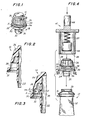
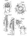
- the reference numeral 10 deontes the corking means of the present invention.
- the corking means 10 is used to stopper bottles 12 with pressurized, carbonated, water-based liquid contents.
- the bottles 12 are discussed in detail hereinafter but generally consist of a body portion (not pictured); an elongated neck portion 14 with two annular flanges 16, 18 thereon; and a mouth portion 20, the flanges being parallel to one another, close to one another and near the mouth portion.
- the corking means 10 is a one-piece moulded plastic unit constructed of elastomeric material.
- the corking means is constructed of a high density polyethylene, but any other appropriate elastomeric material may be used.
- the corking means includes an elongated stopper 22.
- the stopper 22 is capable of being inserted with frictional engagement into the mouth portion 20 of the bottle 12.
- the stopper 22 is generally cylindrical.
- the stopper portion has on it a plurality of integral concentric annular ribs 24. The ribs 24 increase the amount of friction between the stopper 22 and the mouth portion 20 thereby providing a tighter closure for the bottle 12. They also improve the seal effected by the stopper.
- the corking means 10 also has an enlarged head portion 26 which is integral to the stopper 22.
- the head is provided with evenly spaced longitudinal wedges 28.
- the wedges 28 provide a user with a better grip on the head portion 26 at the time the corking means 10 is removed from the bottle 12.
- the corking means 10 is further provided with an annular circumferential ring 30.
- the annular circumferential ring 30 is dimensioned and shaped for snug reception between the two annular flanges 16, 18 of the neck portion 14 of the bottle 12.
- the annular circumferential ring is positioned and spaced below the head portion 26 and is concentric with the stopper 22; it is parallel to the lower surface of the head portion and perpendicular to the longitudinal axis of the stopper.
- the corking means 10 has a flexible, slender elongated tether 32.
- One end 34 of the tether 32 is integrally connected to the bottom of the head portion 26 and the other end 36 of the tether 32 is integrally connected to the top of the annular circumferential ring 30.
- the tether 32 is in a folded state before the corking means 10 is inserted in the bottle 12. In other words, the length of the folded tether 32 is substantially greater than the distance between ends 34 and 36.
- the tether 32 serves to join the head 26 to the ring 30.
- the reaches of the folded tether are disposed in the space between the head and the ring and are oriented circumferentially of the longitudinal axis of the stopper at a radius approximately to that of the ring.
- the corking means Prior to insertion in the bottle, the corking means includes a plurality of frangible bridges 38 which connect the bottom of the head 26 to the top of the ring 30.
- the frangible bridges break when the annular ring 30 is forced between the two flanges 16, 18 as best shown in FIGs. 5, 6, 7, and 9.
- the bottle 12 whose contents are pressurized and carbonated as mentioned heretofore has a mouth portion 20, a body portion (not depicted) and a neck portion 14 with two annular flanges 16 and 18 thereon.
- the two annular flanges 16 and 18 are relatively axially proximate. Further, flanges 16 and 18 are circumferential and squat. The flanges 16 and 18 are spaced apart longitudinally of the neck portion 14 and lie adjacent to the mouth portion 20.
- the bottle 12 may be made of any appropriate material. As the bottle will contain pressurized, carbonated contents, the bottle 12 must be constructed so that it can withstand the pressure of the contents. Further as the contents of the bottle will usually be champagne, the bottle in a preferred embodiment is made of a coloured glass and is shaped and constructed to augment the feelings of celebration and wealth that people usually associate with champagne consumption.
- the diameter of the upper annular neck flange 16 is slightly greater than the diameter of the lower annular neck flange 18. Further, the inner diameter of the annular ring 30 is slightly smaller than the outer diameter of the upper annular neck flange 16. In a preferred embodiment the outer diameter of the upper annular neck flange 16 is about one millimeter more than the outer diameter of the lower annular neck flange 18 and the inner diameter of the annular ring 30 is about 1.5 millimeters less than the outer diameter of the upper annular neck flange 16. The inner diameter of the annular ring 30 is slightly smaller than the outer diameter of the lower annular neck flange 16.
- this respective dimensioning of the two annular neck flanges 16 and 18 and the annular ring 30 permits the annular ring 30 to be pushed down mechanically over the upper neck flange, expanding as it does so, and then constrict and come to rest between the two neck flanges 16 and 18 and further permits the annular ring 30 to be reversibly releasable from its position between the two flanges 16 and 18 by manual pressure in a downward direction to expand over the lower neck flange. This is desirable to facilitate pouring of the bottle contents after removal of the stopper from the bottle 12.
- the neck portion 14 of the bottle 12 is straight in shape for a few inches and then flares outwardly at a small angle. In a preferred embodiment the neck portion 14 is straight for approximately two to three inches below the mouth and then flares outwardly approximately 2 0- 3 0.
- the flexible tether 32 is approximately 1/16 of an inch (1.6 mm) to a side in square cross- section providing a proper amount of flexibility for said tether to perform all of the functions required of it.
- the frangible bridges 38 are broken when the corking means is assembled with the bottle.
- the frangible bridges will stretch and break when the annular ring 30 is forced down between the two annular flanges 16 and 18 inasmuch as the axial distance between the head and ring of the corking means as moulded is less than the distance between these elements as mounted on the bottle. This leaves the flexible tether 32 as the sole connection between the annular ring 30 and the head portion 26.
- the flexible tether 32 partially unfolds.
- the flexible tether 32 is capable of additional unfolding when the corking means 10 is removed from the bottle 12 prior to pouring of the contents of the bottle. In this manner the flexible tether 32 continuously provides a means for joining together the head portion 26 and the annular ring 30. The flexible tether retains the corking means 10 attached to the bottle 12 when the bottle is open and thus prevents the injuries that might occur when the cork of the bottle with pressurized contents is propelled from such a bottle..
- the flexible tether 32 in its unfolded condition is of sufficient length to allow the corking means 10 to be so placed in relationship to the bottle that the corking means 10 does not interfere with the decanting of the bottle contents.
- the flexible tether 32 In its folded and also in its partially unfolded condition, the flexible tether 32 extends circumferentially below the head 26 and does not extend beyond the external peripheries of said head 26 and said annular ring 30. This is particularly advantageous in that it prevents interference by the tether 32 with the wire 40 that is wrapped about the bottle 12 after the corking means is positioned therein.
- the corking means 10 may, in addition to the parts heretofore described, contain at least one frangible connecting element (E) for connecting the flexible tether 32 to at least one other element of the corking means 10.
- the corking means has three such frangible connecting elements, connecting the tether 32 to the annular ring 30, the frangible bridges 38 and the head 26.
- the frangible connecting elements provide, if desired, extra stability to the corking means 10 and further provide additional means to keep all other elements of said corking means in proper alignment to one another prior to assembly with the bottle.
- the present invention provides both a method of and apparatus for stoppering bottles 12 with pressurized, carbonated, water-based contents.
- the bottle provided in the method of this invention is the bottle 12, heretofore described.
- the corking means 10 heretofore described is also provided, as moulded, for stoppering the bottle.
- the stopper portion 22 of the corking means is inserted into the mouth portion 20 of the bottle 12, and the annular ring 30 is concomitantly forced downward until it engages the neck of the bottle between the two annular flanges 16, 18.
- the wire 40 then is wrapped around the corking means and the bottle.
- the wire contains a seal (not depicted) to indicate that the bottle has not been opened previously.
- the corked and wired bottle may be wrapped with a foil-type paper (not depicted).
- the wire 40 used for wrapping the corked bottle is a thin soft steel wire which is standard in the art.
- An apparatus 41 to stoppering the bottle 12 with the corking means 10 also is provided.
- the apparatus includes a locating means 42 for holding the as-moulded corking means 10 in proper position and orientation above an open bottle 12 with the stopper directed downwardly directly above the bottle mouth.
- the locating means may be any appropriate means for so holding the corking means in place. Appropriately it may include plates capable of moving outwardly away from the centre of the corking means 10 to allow the corking means to be positioned in the bottle.
- the apparatus 41 further includes a ram 44 for driving the stopper portion 22 into the mouth portion 20 of the bottle 12 and for concomitantly forcing the annular ring 30 between the two annular flanges 16, 18.
- a ram 44 for driving the stopper portion 22 into the mouth portion 20 of the bottle 12 and for concomitantly forcing the annular ring 30 between the two annular flanges 16, 18.
- the plunger 48 is attached to the ram by a resilient lost motion means 50 which in a preferred embodiment is a compressible spring for yieldingly driving the stopper portion 22 into the mouth portion 20 of the bottle.
- the spring is used because after the stopper portion 22 is driven into the mouth 20 by the plunger 48, the sleeve 46 continues to move downwardly, forcing the annular ring 30 between and over the annular flange 16 to come to rest between the flanges 16, 18.
- the plunger 48 drives the stoppering portion 22 into the mouth portion 20 a split-second before the sleeve 46 forces the annular ring 30 between the flanges 16, 18.
- the frangible bridges 38 and elements E break as the sleeve forces the annular ring between the annular flanges 16, 18.
- the sleeve 46 is dimensioned, shaped and guided to accurately drive the annular ring 30 into position, and the plunger 48 is dimensioned, shaped and guided for accurate driving of the stoppering portion 22 into the mouth portion 20.
Landscapes
- Engineering & Computer Science (AREA)
- Mechanical Engineering (AREA)
- Closures For Containers (AREA)
Claims (13)
Applications Claiming Priority (2)
| Application Number | Priority Date | Filing Date | Title |
|---|---|---|---|
| US22389481A | 1981-01-09 | 1981-01-09 | |
| US223894 | 1981-01-09 |
Publications (2)
| Publication Number | Publication Date |
|---|---|
| EP0056320A1 EP0056320A1 (de) | 1982-07-21 |
| EP0056320B1 true EP0056320B1 (de) | 1984-07-25 |
Family
ID=22838405
Family Applications (1)
| Application Number | Title | Priority Date | Filing Date |
|---|---|---|---|
| EP19820300107 Expired EP0056320B1 (de) | 1981-01-09 | 1982-01-08 | Verfahren und Vorrichtung zum Verschliessen von geänderten Flaschen mit einem aus einem einzigen Stück hergestellten Stöpselelement |
Country Status (5)
| Country | Link |
|---|---|
| EP (1) | EP0056320B1 (de) |
| CA (1) | CA1170214A (de) |
| DE (1) | DE3260407D1 (de) |
| ES (4) | ES270947Y (de) |
| PT (1) | PT74258B (de) |
Families Citing this family (5)
| Publication number | Priority date | Publication date | Assignee | Title |
|---|---|---|---|---|
| US4513870A (en) * | 1981-01-09 | 1985-04-30 | Monarch Wine Co., Inc. | Bottle with a one-piece corking means |
| DE59102589D1 (de) * | 1990-02-23 | 1994-09-29 | Alexander Kau | Korken. |
| IT226094Y1 (it) * | 1990-12-07 | 1997-04-18 | Walter Cananzi | Paraturacciolo |
| CA3022700A1 (en) | 2017-11-27 | 2019-05-27 | Nova Chemicals Corporation | Bottle closure assembly comprising a polyethylene composition having good dimensional stability |
| IT202300019383A1 (it) * | 2023-09-21 | 2025-03-21 | Marco Moroni Sagl | Sistema di sicurezza per l’espulsione di tappi di bottiglia |
Family Cites Families (5)
| Publication number | Priority date | Publication date | Assignee | Title |
|---|---|---|---|---|
| FR1013222A (fr) * | 1950-02-23 | 1952-07-24 | Capsule pour bouteilles | |
| US3145872A (en) * | 1960-10-07 | 1964-08-25 | American Can Co | Captive cap for container |
| DE1200857B (de) * | 1963-06-25 | 1965-09-16 | Linke Hofmann Busch | Eisenbahnkesselwagen fuer den Transport tiefsiedender verfluessigter Gase |
| DE1232494B (de) * | 1964-06-19 | 1967-01-12 | Mauser Kg | Behaelterverschluss |
| FR2329536A1 (fr) * | 1973-07-02 | 1977-05-27 | Somepla Sa | Nouvelle capsule a vis inviolable et imperdable |
-
1982
- 1982-01-08 ES ES1982270947U patent/ES270947Y/es not_active Expired
- 1982-01-08 EP EP19820300107 patent/EP0056320B1/de not_active Expired
- 1982-01-08 DE DE8282300107T patent/DE3260407D1/de not_active Expired
- 1982-01-08 PT PT7425882A patent/PT74258B/pt unknown
- 1982-01-08 CA CA000393806A patent/CA1170214A/en not_active Expired
- 1982-08-10 ES ES1982266863U patent/ES266863Y/es not_active Expired
- 1982-08-10 ES ES514872A patent/ES8308285A1/es not_active Expired
- 1982-08-10 ES ES514871A patent/ES8308284A1/es not_active Expired
Also Published As
| Publication number | Publication date |
|---|---|
| ES514871A0 (es) | 1983-08-16 |
| PT74258A (en) | 1982-02-01 |
| ES266863U (es) | 1983-10-16 |
| ES8308284A1 (es) | 1983-08-16 |
| ES514872A0 (es) | 1983-08-16 |
| CA1170214A (en) | 1984-07-03 |
| DE3260407D1 (en) | 1984-08-30 |
| ES270947Y (es) | 1984-03-01 |
| ES8308285A1 (es) | 1983-08-16 |
| ES266863Y (es) | 1984-04-01 |
| EP0056320A1 (de) | 1982-07-21 |
| PT74258B (en) | 1983-08-23 |
| ES270947U (es) | 1983-08-16 |
Similar Documents
| Publication | Publication Date | Title |
|---|---|---|
| US4564114A (en) | Molded safety closure device | |
| US4583652A (en) | Safety closure device | |
| US4442735A (en) | Champagne cork puller | |
| US5038951A (en) | Closure for monodose bottles and the like, comprising a reservoir provided with a breakable bottom | |
| ES291780U (es) | Un dispositivo de cierre de seguridad con atadura, moldeado que comprende un elemento de cierre destinado a cerrar la boca de una botella. | |
| US8573424B2 (en) | Container, particularly a beverage bottle | |
| US4513870A (en) | Bottle with a one-piece corking means | |
| US4573602A (en) | Molded safety closure device and method for making same | |
| EP0356758A1 (de) | Verschluss für Flaschen und dergleichen, der einen Behälter mit durchstossbarem Boden enthält | |
| US4568004A (en) | Container allowing drop by drop dispensing of a dose of a fluid substance | |
| US4889251A (en) | Cork stopper for bottles of wine | |
| US5025940A (en) | Bottle holder | |
| US5114655A (en) | Method and apparatus for injection molding | |
| IE821327L (en) | Medicine bottle closure | |
| EP0056320B1 (de) | Verfahren und Vorrichtung zum Verschliessen von geänderten Flaschen mit einem aus einem einzigen Stück hergestellten Stöpselelement | |
| US4429799A (en) | Bottle with a one-piece corking means | |
| MX2007008523A (es) | Tapa roscada para botella con anillo no deslizante. | |
| US4435942A (en) | Method and apparatus for stoppering modified bottles with a one-piece corking means | |
| JPH02109866A (ja) | 容器をこじあけできないように密閉するための密閉手段 | |
| US20080197100A1 (en) | Stopper device for a receptacle neck, a receptacle fitted with such a device, and a method of fabricating such a device | |
| US4437291A (en) | Method and apparatus for stoppering modified bottles with a one-piece corking means | |
| AU2006293821A2 (en) | Device for closing a container neck, container equipped with same and method for making same | |
| EP0242453A2 (de) | Metallkappe mit Mitteln um sie teilweise oder gänzlich zu entfernen, insbesondere für Behälter medizinischer Produkte | |
| US2774499A (en) | Bottle stopper | |
| Rizzardi | Plastics Closure for Single-Dose Bottle |
Legal Events
| Date | Code | Title | Description |
|---|---|---|---|
| PUAI | Public reference made under article 153(3) epc to a published international application that has entered the european phase |
Free format text: ORIGINAL CODE: 0009012 |
|
| AK | Designated contracting states |
Designated state(s): DE FR GB IT |
|
| 17P | Request for examination filed |
Effective date: 19830118 |
|
| ITF | It: translation for a ep patent filed | ||
| GRAA | (expected) grant |
Free format text: ORIGINAL CODE: 0009210 |
|
| AK | Designated contracting states |
Designated state(s): DE FR GB IT |
|
| REF | Corresponds to: |
Ref document number: 3260407 Country of ref document: DE Date of ref document: 19840830 |
|
| ET | Fr: translation filed | ||
| PGFP | Annual fee paid to national office [announced via postgrant information from national office to epo] |
Ref country code: DE Payment date: 19850122 Year of fee payment: 4 |
|
| PLBE | No opposition filed within time limit |
Free format text: ORIGINAL CODE: 0009261 |
|
| STAA | Information on the status of an ep patent application or granted ep patent |
Free format text: STATUS: NO OPPOSITION FILED WITHIN TIME LIMIT |
|
| 26N | No opposition filed | ||
| PG25 | Lapsed in a contracting state [announced via postgrant information from national office to epo] |
Ref country code: GB Effective date: 19890108 |
|
| GBPC | Gb: european patent ceased through non-payment of renewal fee | ||
| PG25 | Lapsed in a contracting state [announced via postgrant information from national office to epo] |
Ref country code: FR Free format text: LAPSE BECAUSE OF NON-PAYMENT OF DUE FEES Effective date: 19890929 |
|
| PG25 | Lapsed in a contracting state [announced via postgrant information from national office to epo] |
Ref country code: DE Effective date: 19891003 |
|
| REG | Reference to a national code |
Ref country code: FR Ref legal event code: ST |