EP0056328B1 - Wiederherstellung einer Schaufel - Google Patents
Wiederherstellung einer Schaufel Download PDFInfo
- Publication number
- EP0056328B1 EP0056328B1 EP82300128A EP82300128A EP0056328B1 EP 0056328 B1 EP0056328 B1 EP 0056328B1 EP 82300128 A EP82300128 A EP 82300128A EP 82300128 A EP82300128 A EP 82300128A EP 0056328 B1 EP0056328 B1 EP 0056328B1
- Authority
- EP
- European Patent Office
- Prior art keywords
- blade
- lacing wire
- turbine blade
- heat treatment
- turbine
- Prior art date
- Legal status (The legal status is an assumption and is not a legal conclusion. Google has not performed a legal analysis and makes no representation as to the accuracy of the status listed.)
- Expired
Links
- 230000008439 repair process Effects 0.000 title description 18
- 238000000034 method Methods 0.000 claims abstract description 48
- 238000010438 heat treatment Methods 0.000 claims abstract description 30
- 239000000463 material Substances 0.000 claims abstract description 30
- 238000003466 welding Methods 0.000 claims abstract description 26
- 239000002184 metal Substances 0.000 claims abstract description 17
- 238000003754 machining Methods 0.000 claims abstract description 9
- 239000007787 solid Substances 0.000 claims description 3
- 238000002407 reforming Methods 0.000 claims description 2
- 230000003628 erosive effect Effects 0.000 description 9
- 229910000669 Chrome steel Inorganic materials 0.000 description 6
- 239000002245 particle Substances 0.000 description 6
- 229910001347 Stellite Inorganic materials 0.000 description 4
- AHICWQREWHDHHF-UHFFFAOYSA-N chromium;cobalt;iron;manganese;methane;molybdenum;nickel;silicon;tungsten Chemical compound C.[Si].[Cr].[Mn].[Fe].[Co].[Ni].[Mo].[W] AHICWQREWHDHHF-UHFFFAOYSA-N 0.000 description 4
- 230000015572 biosynthetic process Effects 0.000 description 2
- 230000007797 corrosion Effects 0.000 description 2
- 238000005260 corrosion Methods 0.000 description 2
- 238000005336 cracking Methods 0.000 description 2
- VYZAMTAEIAYCRO-UHFFFAOYSA-N Chromium Chemical compound [Cr] VYZAMTAEIAYCRO-UHFFFAOYSA-N 0.000 description 1
- 229910000760 Hardened steel Inorganic materials 0.000 description 1
- 238000005452 bending Methods 0.000 description 1
- 238000005219 brazing Methods 0.000 description 1
- 230000001419 dependent effect Effects 0.000 description 1
- 238000005553 drilling Methods 0.000 description 1
- 238000012423 maintenance Methods 0.000 description 1
- 238000011179 visual inspection Methods 0.000 description 1
- XLYOFNOQVPJJNP-UHFFFAOYSA-N water Substances O XLYOFNOQVPJJNP-UHFFFAOYSA-N 0.000 description 1
Images


Classifications
-
- B—PERFORMING OPERATIONS; TRANSPORTING
- B23—MACHINE TOOLS; METAL-WORKING NOT OTHERWISE PROVIDED FOR
- B23P—METAL-WORKING NOT OTHERWISE PROVIDED FOR; COMBINED OPERATIONS; UNIVERSAL MACHINE TOOLS
- B23P6/00—Restoring or reconditioning objects
- B23P6/002—Repairing turbine components, e.g. moving or stationary blades, rotors
-
- B—PERFORMING OPERATIONS; TRANSPORTING
- B23—MACHINE TOOLS; METAL-WORKING NOT OTHERWISE PROVIDED FOR
- B23P—METAL-WORKING NOT OTHERWISE PROVIDED FOR; COMBINED OPERATIONS; UNIVERSAL MACHINE TOOLS
- B23P15/00—Making specific metal objects by operations not covered by a single other subclass or a group in this subclass
- B23P15/02—Making specific metal objects by operations not covered by a single other subclass or a group in this subclass turbine or like blades from one piece
-
- F—MECHANICAL ENGINEERING; LIGHTING; HEATING; WEAPONS; BLASTING
- F01—MACHINES OR ENGINES IN GENERAL; ENGINE PLANTS IN GENERAL; STEAM ENGINES
- F01D—NON-POSITIVE DISPLACEMENT MACHINES OR ENGINES, e.g. STEAM TURBINES
- F01D5/00—Blades; Blade-carrying members; Heating, heat-insulating, cooling or antivibration means on the blades or the members
- F01D5/005—Repairing methods or devices
-
- Y—GENERAL TAGGING OF NEW TECHNOLOGICAL DEVELOPMENTS; GENERAL TAGGING OF CROSS-SECTIONAL TECHNOLOGIES SPANNING OVER SEVERAL SECTIONS OF THE IPC; TECHNICAL SUBJECTS COVERED BY FORMER USPC CROSS-REFERENCE ART COLLECTIONS [XRACs] AND DIGESTS
- Y10—TECHNICAL SUBJECTS COVERED BY FORMER USPC
- Y10T—TECHNICAL SUBJECTS COVERED BY FORMER US CLASSIFICATION
- Y10T29/00—Metal working
- Y10T29/49—Method of mechanical manufacture
- Y10T29/49316—Impeller making
- Y10T29/49318—Repairing or disassembling
-
- Y—GENERAL TAGGING OF NEW TECHNOLOGICAL DEVELOPMENTS; GENERAL TAGGING OF CROSS-SECTIONAL TECHNOLOGIES SPANNING OVER SEVERAL SECTIONS OF THE IPC; TECHNICAL SUBJECTS COVERED BY FORMER USPC CROSS-REFERENCE ART COLLECTIONS [XRACs] AND DIGESTS
- Y10—TECHNICAL SUBJECTS COVERED BY FORMER USPC
- Y10T—TECHNICAL SUBJECTS COVERED BY FORMER US CLASSIFICATION
- Y10T29/00—Metal working
- Y10T29/49—Method of mechanical manufacture
- Y10T29/49718—Repairing
- Y10T29/49746—Repairing by applying fluent material, e.g., coating, casting
-
- Y—GENERAL TAGGING OF NEW TECHNOLOGICAL DEVELOPMENTS; GENERAL TAGGING OF CROSS-SECTIONAL TECHNOLOGIES SPANNING OVER SEVERAL SECTIONS OF THE IPC; TECHNICAL SUBJECTS COVERED BY FORMER USPC CROSS-REFERENCE ART COLLECTIONS [XRACs] AND DIGESTS
- Y10—TECHNICAL SUBJECTS COVERED BY FORMER USPC
- Y10T—TECHNICAL SUBJECTS COVERED BY FORMER US CLASSIFICATION
- Y10T29/00—Metal working
- Y10T29/49—Method of mechanical manufacture
- Y10T29/49718—Repairing
- Y10T29/49748—Repairing by shaping, e.g., bending, extruding, turning, etc.
- Y10T29/4975—Repairing by shaping, e.g., bending, extruding, turning, etc. including heating
Definitions
- the present invention relates to a method of repairing turbine blades.
- the type of turbine blade assembly which may comprise a rotor or a stator, in which a repair by welding has been found to be not satisfactory is that in which adjacent blades are interconnected, usually in the region of their outer ends by snubbers, lacing wires or other members requiring a hole or other discontinuity to be formed in the turbine blade (all such members being hereinafter referred to for convenience as lacing wires and the discontinuities as lacing wire holes).
- lacing wires are to prevent excessive relative movement between the blades and to generally dampen any vibration during operation of the turbine. Such lacing wires therefore render the turbine structure more rigid but do not prevent all relative movement between the blades.
- the outer end of the turbine blade in a rotor assembly is the part which has the greatest linear speed in use, it is the outer end that is most prone to erosion. Erosion generally occurs because of contact between the turbine blades with particles carried by the steam and also with the steam itself.
- the blades are generally subjected to damage from particles of solid matter carried by the steam due to contact between the blades and the particles, and since the rate of erosion will be dependent on relative speeds between the blades and particles, it is generally the leading edge at the outer end of each blade that is most prone to erosion by impact between the particles and said edges.
- the steam At the low pressure end of the turbine, the steam is at a lower temperature having been cooled during passage through the turbine and water condenses therefrom more readily.
- the steam is therefore wetter and the transfer of energy by impact on the turbine blade of the steam itself is greater at the low pressure end of the turbine than that at the high pressure end.
- it is predominantly the outer ends of the blades which are especially subject to erosion.
- Turbine blades are often made from a chrome steel and the insert may be made from stellite or a suitable hardened steel, in which case the insert may be brazed to the blade. If the blade has not originally been formed with such an insert and is subsequently required to be repaired, the turbine blade may then have such an insert introduced. In which case, the insert may be secured to the remainder of the turbine blade by welding process, the blade end being subsequently machined to restore it to its original form.
- the filling of the lacing wire holes may be effected at any stage of the repairing method prior to heat treatment process and, is preferably carried out at the same time as the addition of metal by welding.
- plugs have only a temporary function to perform, it is contemplated that they need not always be made of the same material as that of which the blade itself is made. Such plugs do, however, have to be capable of performing the required function, namely maintenance of the condition of the metal of the blade around the holes during the heat treatment in a state such as to avoid the tendency to local crack formation in subsequent service.
- compatible is used herein to identify such other material.
- Machining of the blade may be carried out before or after the heat treatment process provided the machining does not generate heat in sufficient quantities to bring about residual stress in the turbine blade.
- the blade may therefore after the addition of metal be subjected to mechanical forces to return the blade to its original shape.
- Said subjecting of the blade to mechanical forces preferably takes place before said heat treatment process such that the heat treatment is effective to eliminate any stress in the turbine blade and is preferably carried out after filling of the lacing wire holes in order to eliminate the possibility of causing damage in the region of the lacing wire holes by the application of mechanical forces.
- lacing wire holes may be in an area which is eroded and hence in an area which as such is in need of repair, the heating and consequent stressing of the turbine blade caused by the repair in other adjacent areas, and subsequent heat treatment and possible mechanical stressing, affects the structure of the material in the vicinity of or around the lacing wire holes and thus increases the risk of crack formation leading to subsequent failure of the turbine blade.
- the phenomenon of "stress corrosion cracking" occurring in use around the lacing wire holes may be due to concentration of residual stress in the region of the lacing wire holes during application of mechanical forces to the turbine blade, it being necessary to maintain or return the blade to its correct shape after repair.
- the lacing wire holes may be filled by introduction of the welding metal itself or introduction of a new piece of solid state material welded into the hole. In both cases the lacing wire holes will be filled at least before heat treatment.
- FIG. 1 and 1A three turbine blades are shown 10, 11 and 12, each turbine blade having through bores 13 and 14 through which pass respective lacing wires 15 and 16.
- the lacing wires 15 and 16 can pass either with clearance through their respective through bores 13 and 14 in the turbine blades, or may be joined to each turbine blade by welding for example.
- Figure 1A illustrates an example of a rotor from a turbine, the three turbine blades 10, 11 and 12 shown in Figure 1 being three of a considerable number of blades forming the complete array in the rotor.
- the turbine blades such as those shown at 10, 11, 12, can be made from a variety of materials depending on the function and operating conditions of the turbine.
- a typical material from which a blade in a steam turbine may be manufactured is chrome steel being approximately 12% chrome.
- the area of the turbine blade which is most prone to erosion is illustrated, this being the leading edge 17 of the outer end of the turbine blade since it is this part of the blade which "collides” with the steam or particles carried thereby during use of the turbine, and which also has the greatest linear speed being the radially outermost point from the axis of rotation.
- the leading edge 17 is the edge which is nearest the steam inlet end of the turbine.
- Figure 3 illustfates the area where erosion is most likely to occur on the leading edge 17 of the turbine blade 10, and which erosion even though it may be severe, is not normally so extensive as to reach as far as the nearest lacing hole 13.
- a piece of material is cut out from the margin bordering the leading edge 17 and a new piece 18 of hard material, such as Stellite, is welded to the remainder of the turbine blade 10.
- the material used for welding is one able to form a welded function with the material from which the blade is made, for example, 12% chrome steel and the material, i.e. Stellite, which is to be welded to the turbine blade 10.
- a suitable welding material is 12% chrome steel.
- the lacing wire holes 13 and 14 are filled by welding in plugs 20 and 21 which may be of the same material from which the turbine blade is made, i.e. 12% chrome steel, and once again a suitable welding metal will be used to secure these plugs in position.
- the excess material may at this stage be machined to restore the blade to its proper shape or provided that the machining does not unduly raise the temperature of the turbine blade, the machining can be carried out at a later stage in the repair process.
- the next stage in the repair process is to heat the blade to a predetermined temperature to relieve any residual stress in the blade.
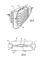
- the heat treatment may be carried out in any suitable oven 60, the temperature to which the blade is heated and the time to which it is subjected to such heat, depending on the size of the turbine blade and the material from which it is made.
- a typical heat treatment for a blade made from a 12% chrome steel being 1 hour at 660°C.
- the reforming of the blade may involve the step of causing a twisting of the blade between its ends and a simple apparatus for carrying out such twisting is illustrated in Figure 10.
- the root end 24 is held in a vice 25 and the other end 26 is held in a second vice 27 which is pivotally mounted about an axis 28.
- the vice 27 carries a lever arm 29 having a helically threaded through bore 30 into which extends a helically threaded member 31, which also extends through a helically threaded nut part 32 secured to base member 33.
- the helically threaded member 31 is provided with a handle 34 by means of which the helically threaded member 31 may be rotated causing pivotal movement of the second vice 26. Since the root end 24 of the turbine blade 20 is held in the vice 25, the turbine blade 10 will be twisted about its longitudinal axis and sufficient mechanical force is used to twist the turbine blade 10 until it has the correct form after having been released from the vices 25 and 27.
- a modified apparatus may be provided in which the vices 25 and 27 are movable towards and away from each other along an axis parallel with the turbine blade longitudinally, thereby enabling the blade 10 to be gripped at any two positions along its length.
- the blade is subjected to heat treatment, for example as in the oven 60 shown in Figure 11, and then the form and shape of the blade may be checked by a gauge such as that shown in Figures 12 and 13.
- the gauge shown in Figures 12 and 13 comprises a base member 40 having a pair of upwardly extending support members 41 and 42, each of the members 41 and 42 being provided with horizontally aligned slots 43 and 44 respectively.
- each pair of horizontally opposed slots 43 and 44 Extending between and located in each pair of horizontally opposed slots 43 and 44 are a pair of gauge members 45 and 46.
- Each of the gauge members 45 and 46 which comprise metal plates have a cut-out 47 and 48 respectively which corresponds to half the desired cross-sectional profile of the turbine blade 10 at a distance from the base member 40 determined by the distance from the base of the respective horizontally opposed channels 42 and 43.
- the turbine blade 10 In order to check if the turbine blade 10 is of the correct form and shape, it is carefully positioned on the base member 40 and the gauge plates 45 and 46 inserted into their respective channels 42 and 43 and moved into contact with the turbine blade 10. If the gauge plates 45 and 46 do not fit around the turbine blade perfectly, i.e. there is a gap at any position between a gauge plate and the turbine blade, either the form or shape of the blade requires some correction, the form being corrected by imparting a twisting force to the blade as aforedescribed, and the shape being corrected by the addition or removal of material by welding or grinding respectively for example.
- the lacing wire holes 13 and 14 are reformed, for example by drilling. However, in normal circumstances the lacing wire holes will not be reformed until the turbine blade has been gauged and found correct in form and shape, since if it is not correct and further reshaping and re-forming is necessary.
- the turbine blade 10 will be subjected to heat treatment and if the form and shape is not correct, it will be subjected to mechanical forces to twist the turbine blade to the correct form and/or machining, after which heat treatment will follow and the cycle of application of mechanical forces, heat treatment and measuring by the gauge will be continued until the gauged turbine blade is found to be correct.
Landscapes
- Engineering & Computer Science (AREA)
- Mechanical Engineering (AREA)
- General Engineering & Computer Science (AREA)
- Turbine Rotor Nozzle Sealing (AREA)
- Coating By Spraying Or Casting (AREA)
Claims (8)
dadurch gekennzeichnet, daß das Verfahren vor dem Wärmebehandlungsprozeß weiter den Schritt aufweist:
Priority Applications (1)
| Application Number | Priority Date | Filing Date | Title |
|---|---|---|---|
| AT82300128T ATE24138T1 (de) | 1981-01-12 | 1982-01-11 | Wiederherstellung einer schaufel. |
Applications Claiming Priority (2)
| Application Number | Priority Date | Filing Date | Title |
|---|---|---|---|
| GB8100780 | 1981-01-12 | ||
| GB8100780 | 1981-01-12 |
Publications (3)
| Publication Number | Publication Date |
|---|---|
| EP0056328A2 EP0056328A2 (de) | 1982-07-21 |
| EP0056328A3 EP0056328A3 (en) | 1984-03-28 |
| EP0056328B1 true EP0056328B1 (de) | 1986-12-10 |
Family
ID=10518919
Family Applications (1)
| Application Number | Title | Priority Date | Filing Date |
|---|---|---|---|
| EP82300128A Expired EP0056328B1 (de) | 1981-01-12 | 1982-01-11 | Wiederherstellung einer Schaufel |
Country Status (8)
| Country | Link |
|---|---|
| US (1) | US4866828A (de) |
| EP (1) | EP0056328B1 (de) |
| AT (1) | ATE24138T1 (de) |
| AU (1) | AU546843B2 (de) |
| CA (1) | CA1189692A (de) |
| DE (1) | DE3274629D1 (de) |
| GB (1) | GB2091139B (de) |
| ZA (1) | ZA82174B (de) |
Cited By (1)
| Publication number | Priority date | Publication date | Assignee | Title |
|---|---|---|---|---|
| CN103753098A (zh) * | 2013-12-31 | 2014-04-30 | 上海彩石激光科技有限公司 | 涡轮发动机叶片自动化修复设备及其修复方法 |
Families Citing this family (49)
| Publication number | Priority date | Publication date | Assignee | Title |
|---|---|---|---|---|
| ZA831106B (en) * | 1982-02-20 | 1983-11-30 | Refurbished Turbine Components | Method of repairing turbine blade |
| GB2198667B (en) * | 1986-12-20 | 1991-08-07 | Refurbished Turbine Components | Parts for and methods of repairing machines |
| US4793043A (en) * | 1987-07-07 | 1988-12-27 | Cummins Engine Company, Inc. | Fuel pump distribution assembly salvage method |
| US5048183A (en) * | 1988-08-26 | 1991-09-17 | Solar Turbines Incorporated | Method of making and repairing turbine blades |
| GB8821812D0 (en) * | 1988-09-16 | 1988-10-19 | Refurbished Turbine Components | Turbine blade repair |
| GB2227191B (en) * | 1988-09-16 | 1993-03-03 | Refurbished Turbine Components | Turbine blade repair |
| GB2227190B (en) * | 1989-01-24 | 1992-12-16 | Refurbished Turbine Components | Turbine blade repair |
| GB8906929D0 (en) * | 1989-03-28 | 1989-05-10 | Refurbished Turbine Components | Method of repairing turbine blades |
| ATE167418T1 (de) * | 1989-03-28 | 1998-07-15 | Refurbished Turbine Components | Reparaturverfahren für turbinenschaufeln |
| US5235745A (en) * | 1989-06-20 | 1993-08-17 | Refurbished Turbine Components Limited | Method of repairing turbine blades on a rotor |
| GB8929005D0 (en) * | 1989-12-22 | 1990-02-28 | Refurbished Turbine Components | Turbine blade repair |
| GB2244943B (en) * | 1990-06-12 | 1994-03-30 | Turbine Blading Ltd | Method of repair of turbines |
| US5193736A (en) * | 1991-03-01 | 1993-03-16 | Interturbine Corporation | Method for repairing turbine vanes |
| GB9109016D0 (en) * | 1991-04-26 | 1991-06-12 | Turbine Blading Ltd | Turbine blade repair |
| US5248241A (en) * | 1991-10-21 | 1993-09-28 | Southern California Edison Co. | Components made of hardenable and non-hardenable materials |
| DE4226272C1 (de) * | 1992-08-08 | 1994-02-10 | Mtu Muenchen Gmbh | Verfahren zur Behandlung von MCrAlZ-Schichten und mit dem Verfahren hergestellte Bauteile |
| US5285572A (en) * | 1992-08-12 | 1994-02-15 | General Electric Company | Method and system for machining contoured parts |
| US20030088980A1 (en) * | 1993-11-01 | 2003-05-15 | Arnold James E. | Method for correcting defects in a workpiece |
| GB2284367B (en) * | 1993-12-02 | 1997-02-26 | Turbine Blading Ltd | Turbine blade repair |
| US20040018299A1 (en) * | 1996-12-23 | 2004-01-29 | Arnold James E. | Method of forming a diffusion coating on the surface of a workpiece |
| BR9714974A (pt) * | 1996-12-23 | 2000-10-03 | James E Arnold | Método de tratamento dos componentes metálicos |
| US6003755A (en) * | 1997-02-20 | 1999-12-21 | Lockheed Martin Corp. | Method for repair welding aluminum-lithium alloys |
| US6454156B1 (en) * | 2000-06-23 | 2002-09-24 | Siemens Westinghouse Power Corporation | Method for closing core printout holes in superalloy gas turbine blades |
| US6606541B2 (en) * | 2001-04-30 | 2003-08-12 | United Technologies Corporation | Automated system for repairing components |
| US6792655B2 (en) * | 2001-11-09 | 2004-09-21 | General Electric Company | Apparatus for correcting airfoil twist |
| DE10200401A1 (de) * | 2002-01-08 | 2003-07-24 | Aloys Wobben | Vorrichtung zum Handhaben von Stückgütern |
| JP4028442B2 (ja) | 2002-06-26 | 2007-12-26 | 株式会社東芝 | ガスタービン翼の変形修正装置及び方法 |
| GB2397544B (en) * | 2003-01-23 | 2006-02-22 | Innogy Plc | Turbine refurbishment |
| US7051435B1 (en) | 2003-06-13 | 2006-05-30 | General Electric Company | Process for repairing turbine components |
| US8844090B2 (en) | 2005-06-17 | 2014-09-30 | United Technologies Corporation | Tool for filling voids in turbine vanes and other articles |
| US7503113B2 (en) * | 2005-10-13 | 2009-03-17 | Siemens Energy, Inc. | Turbine vane airfoil reconfiguration system |
| US7536783B2 (en) * | 2005-10-13 | 2009-05-26 | Siemens Energy, Inc. | Turbine vane airfoil reconfiguration method |
| US20090178278A1 (en) * | 2008-01-16 | 2009-07-16 | Quinn Daniel E | Method of reverse engineering |
| SG155788A1 (en) * | 2008-03-18 | 2009-10-29 | Turbine Overhaul Services Pte | Methods and apparatuses for correcting twist angle in a gas turbine engine blade |
| US8122601B2 (en) * | 2008-04-15 | 2012-02-28 | United Technologies Corporation | Methods for correcting twist angle in a gas turbine engine blade |
| US8127581B2 (en) * | 2008-04-15 | 2012-03-06 | United Technologies Corporation | Turbine blade twist angle correction tooling |
| US7970555B2 (en) * | 2008-04-15 | 2011-06-28 | United Technologies Corporation | Method for developing a repair process to correct a deformed gas turbine engine component |
| US8523525B2 (en) * | 2010-02-05 | 2013-09-03 | Siemens Energy, Inc. | Snubber assembly for turbine blades |
| US8684692B2 (en) * | 2010-02-05 | 2014-04-01 | Siemens Energy, Inc. | Cooled snubber structure for turbine blades |
| KR101530121B1 (ko) | 2010-04-07 | 2015-06-18 | 보벤 프로퍼티즈 게엠베하 | 풍력 발전소의 회전자 블레이드 및/또는 타워 세그먼트용 운반 차량 및 운반 차량용 운반 랙 |
| US9018560B2 (en) * | 2011-02-28 | 2015-04-28 | General Electric Company | Repair alignment method and apparatus for turbine components |
| DE102012211877B4 (de) | 2012-07-06 | 2016-09-29 | Wobben Properties Gmbh | Vorrichtung zum Handhaben eines Windenergieanlagen-Rotorblattes |
| US9435212B2 (en) * | 2013-11-08 | 2016-09-06 | Siemens Energy, Inc. | Turbine airfoil with laterally extending snubber having internal cooling system |
| US9506365B2 (en) | 2014-04-21 | 2016-11-29 | Honeywell International Inc. | Gas turbine engine components having sealed stress relief slots and methods for the fabrication thereof |
| US20150314403A1 (en) * | 2014-05-01 | 2015-11-05 | Siemens Energy, Inc. | Arrangement for laser processing of turbine component |
| JP6508568B2 (ja) * | 2015-03-26 | 2019-05-08 | 日立金属株式会社 | タービンブレード用素材の形状矯正方法及びタービンブレード用素材の製造方法 |
| CN106216937B (zh) * | 2016-08-16 | 2018-11-27 | 贵州安吉航空精密铸造有限责任公司 | 一种zl114a铝合金铸件内部冶金缺陷的修复方法 |
| CN109955026B (zh) * | 2017-12-22 | 2020-08-21 | 中核核电运行管理有限公司 | 一种用于核级闸阀阀板密封面修复工艺 |
| FR3081733B1 (fr) * | 2018-06-05 | 2020-12-11 | Safran Aircraft Engines | Outillage de vrillage d'une aube de turbomachine |
Family Cites Families (12)
| Publication number | Priority date | Publication date | Assignee | Title |
|---|---|---|---|---|
| GB309235A (en) * | 1928-01-11 | 1929-04-11 | Charles Algernon Parsons | Improvements in and relating to turbines |
| US1751570A (en) * | 1928-03-21 | 1930-03-25 | Westinghouse Electric & Mfg Co | Turbine blading |
| US2632944A (en) * | 1950-09-18 | 1953-03-31 | Engineering Dev Corp | Process for controlling warpage in iron castings during welding |
| US3449816A (en) * | 1967-04-24 | 1969-06-17 | Dwain K Swick | Method of repairing screw-in precombustion chamber type openings in cylinder heads |
| AT275283B (de) * | 1967-05-26 | 1969-10-27 | Boehler & Co Ag Geb | Verfahren zur Herstellung von Turbinenschaufeln |
| US3528200A (en) * | 1968-06-17 | 1970-09-15 | Chromalloy American Corp | Apparatus for contour grinding of vanes and blades |
| US3574924A (en) * | 1968-10-28 | 1971-04-13 | North American Rockwell | Solid state repair method and means |
| GB1233730A (de) * | 1968-12-11 | 1971-05-26 | ||
| AT293148B (de) * | 1969-04-28 | 1971-09-27 | Boehler & Co Ag Geb | Verfahren zur Herstellung von Turbinenschaufeln |
| DE2054549A1 (de) * | 1970-11-05 | 1972-05-10 | North American Rockwell | Verfahren und Vorrichtung zur Wiederinstandsetzung eines festen Körpers |
| US4028787A (en) * | 1975-09-15 | 1977-06-14 | Cretella Salvatore | Refurbished turbine vanes and method of refurbishment thereof |
| US4155152A (en) * | 1977-12-12 | 1979-05-22 | Matthew Bernardo | Method of restoring the shrouds of turbine blades |
-
1982
- 1982-01-11 DE DE8282300128T patent/DE3274629D1/de not_active Expired
- 1982-01-11 EP EP82300128A patent/EP0056328B1/de not_active Expired
- 1982-01-11 AU AU79425/82A patent/AU546843B2/en not_active Expired
- 1982-01-11 AT AT82300128T patent/ATE24138T1/de not_active IP Right Cessation
- 1982-01-11 GB GB8200688A patent/GB2091139B/en not_active Expired
- 1982-01-12 CA CA000393940A patent/CA1189692A/en not_active Expired
- 1982-01-12 ZA ZA82174A patent/ZA82174B/xx unknown
-
1984
- 1984-06-08 US US06/618,318 patent/US4866828A/en not_active Expired - Lifetime
Cited By (1)
| Publication number | Priority date | Publication date | Assignee | Title |
|---|---|---|---|---|
| CN103753098A (zh) * | 2013-12-31 | 2014-04-30 | 上海彩石激光科技有限公司 | 涡轮发动机叶片自动化修复设备及其修复方法 |
Also Published As
| Publication number | Publication date |
|---|---|
| ATE24138T1 (de) | 1986-12-15 |
| GB2091139B (en) | 1984-05-23 |
| AU7942582A (en) | 1982-07-22 |
| AU546843B2 (en) | 1985-09-26 |
| EP0056328A3 (en) | 1984-03-28 |
| DE3274629D1 (en) | 1987-01-22 |
| CA1189692A (en) | 1985-07-02 |
| US4866828A (en) | 1989-09-19 |
| GB2091139A (en) | 1982-07-28 |
| EP0056328A2 (de) | 1982-07-21 |
| ZA82174B (en) | 1982-12-29 |
Similar Documents
| Publication | Publication Date | Title |
|---|---|---|
| EP0056328B1 (de) | Wiederherstellung einer Schaufel | |
| EP0359585B1 (de) | Reparatur einer Turbinenschaufel | |
| EP0101164B1 (de) | Verfahren zum Reparieren von Turbinenschaufeln | |
| US5914055A (en) | Rotor repair system and technique | |
| CA1289890C (en) | Parts for and methods of repairing turbine blades | |
| CN1100642C (zh) | 焊接修复工艺及用此工艺修复的制品 | |
| JPH0333402A (ja) | タービンブレードの修理方法又は改善方法 | |
| US4896408A (en) | Method of repairing turbine blades | |
| EP0087279B1 (de) | Verfahren zum Reparieren einer Turbinenschaufel | |
| EP0558053A1 (de) | Reparaturmethode für Turbinenschaufeln | |
| US5831241A (en) | Optimized welding technique for NiMoV rotors for high temperature applications | |
| EP0359586B1 (de) | Reparatur einer Turbinenschaufel | |
| EP0462487B1 (de) | Reparaturweise von Turbinenschaufeln | |
| WO2009005721A1 (en) | Turbine vane restoration system | |
| US5755030A (en) | Turbine blade repair | |
| CN106808121B (zh) | 用于在薄壁零件补焊修复过程中防止薄壁零件变形的方法 | |
| GB2091140A (en) | Turbine blades repair | |
| US5012800A (en) | Mechanical-metallurgic process for repairing machines or machine components damaged by cracks, fissures, wearings or squashes made of metallic material difficult to weld and of any forms | |
| GB2255920A (en) | "parts for and methods of repairing turbine blades" | |
| KR20230036876A (ko) | 터빈의 버켓 커버 용접 방법 및 회전체 구조물의 정비 신뢰성 평가 방법 | |
| WO2004065051A1 (en) | Turbine refurbishment | |
| Hendelman et al. | The refurbishment of rotating steam turbine blades |
Legal Events
| Date | Code | Title | Description |
|---|---|---|---|
| PUAI | Public reference made under article 153(3) epc to a published international application that has entered the european phase |
Free format text: ORIGINAL CODE: 0009012 |
|
| AK | Designated contracting states |
Designated state(s): AT BE CH DE FR IT LU NL SE |
|
| PUAL | Search report despatched |
Free format text: ORIGINAL CODE: 0009013 |
|
| AK | Designated contracting states |
Designated state(s): AT BE CH DE FR IT LI LU NL SE |
|
| 17P | Request for examination filed |
Effective date: 19840924 |
|
| GRAA | (expected) grant |
Free format text: ORIGINAL CODE: 0009210 |
|
| ITF | It: translation for a ep patent filed | ||
| AK | Designated contracting states |
Kind code of ref document: B1 Designated state(s): AT BE CH DE FR IT LI LU NL SE |
|
| PG25 | Lapsed in a contracting state [announced via postgrant information from national office to epo] |
Ref country code: LI Effective date: 19861210 Ref country code: CH Effective date: 19861210 Ref country code: BE Effective date: 19861210 Ref country code: AT Effective date: 19861210 |
|
| REF | Corresponds to: |
Ref document number: 24138 Country of ref document: AT Date of ref document: 19861215 Kind code of ref document: T |
|
| PG25 | Lapsed in a contracting state [announced via postgrant information from national office to epo] |
Ref country code: SE Effective date: 19861231 |
|
| REF | Corresponds to: |
Ref document number: 3274629 Country of ref document: DE Date of ref document: 19870122 |
|
| PG25 | Lapsed in a contracting state [announced via postgrant information from national office to epo] |
Ref country code: LU Free format text: LAPSE BECAUSE OF NON-PAYMENT OF DUE FEES Effective date: 19870131 |
|
| REG | Reference to a national code |
Ref country code: CH Ref legal event code: PL |
|
| ET | Fr: translation filed | ||
| PLBE | No opposition filed within time limit |
Free format text: ORIGINAL CODE: 0009261 |
|
| STAA | Information on the status of an ep patent application or granted ep patent |
Free format text: STATUS: NO OPPOSITION FILED WITHIN TIME LIMIT |
|
| 26N | No opposition filed | ||
| BERE | Be: lapsed |
Owner name: REFURBISHED TURBINE COMPONENTS LIMITED Effective date: 19880131 |
|
| ITTA | It: last paid annual fee | ||
| PGFP | Annual fee paid to national office [announced via postgrant information from national office to epo] |
Ref country code: FR Payment date: 20010226 Year of fee payment: 20 |
|
| PGFP | Annual fee paid to national office [announced via postgrant information from national office to epo] |
Ref country code: NL Payment date: 20010227 Year of fee payment: 20 |
|
| PGFP | Annual fee paid to national office [announced via postgrant information from national office to epo] |
Ref country code: DE Payment date: 20010306 Year of fee payment: 20 |
|
| PG25 | Lapsed in a contracting state [announced via postgrant information from national office to epo] |
Ref country code: FR Free format text: LAPSE BECAUSE OF NON-PAYMENT OF DUE FEES Effective date: 20010928 |
|
| REG | Reference to a national code |
Ref country code: FR Ref legal event code: ST |
|
| PG25 | Lapsed in a contracting state [announced via postgrant information from national office to epo] |
Ref country code: NL Free format text: LAPSE BECAUSE OF EXPIRATION OF PROTECTION Effective date: 20020111 |
|
| REG | Reference to a national code |
Ref country code: FR Ref legal event code: D3 |
|
| NLV7 | Nl: ceased due to reaching the maximum lifetime of a patent |
Effective date: 20020111 |