EP0056419A1 - Sicherheitsmechanismus für industrielle roboter - Google Patents
Sicherheitsmechanismus für industrielle roboter Download PDFInfo
- Publication number
- EP0056419A1 EP0056419A1 EP81902242A EP81902242A EP0056419A1 EP 0056419 A1 EP0056419 A1 EP 0056419A1 EP 81902242 A EP81902242 A EP 81902242A EP 81902242 A EP81902242 A EP 81902242A EP 0056419 A1 EP0056419 A1 EP 0056419A1
- Authority
- EP
- European Patent Office
- Prior art keywords
- robot
- industrial robot
- movable part
- lock plate
- male
- Prior art date
- Legal status (The legal status is an assumption and is not a legal conclusion. Google has not performed a legal analysis and makes no representation as to the accuracy of the status listed.)
- Withdrawn
Links
Images

Classifications
-
- B—PERFORMING OPERATIONS; TRANSPORTING
- B25—HAND TOOLS; PORTABLE POWER-DRIVEN TOOLS; MANIPULATORS
- B25J—MANIPULATORS; CHAMBERS PROVIDED WITH MANIPULATION DEVICES
- B25J19/00—Accessories fitted to manipulators, e.g. for monitoring, for viewing; Safety devices combined with or specially adapted for use in connection with manipulators
- B25J19/06—Safety devices
Definitions
- the present invention relates to an industrial robot used so as to cooperate with machines, such as automatic machine tools, and more particularly relates to a safeguard mechanism of an industrial robot provided in order to prevent accidents, such as collision of a movable part of the robot with a machine or machines located around the robot or injury to the operator resulting from the operator being struck by a movable part of the robot, which might occur when the movable part of the robot is moved by the generation of erroneous control signals or by the application of noise signals from outside the industrial robot, the mechanism being capable of enhancing the operational safety of the industrial robot.
- industrial robots have been used so as to cooperate with machines, such as automatic machine tools, for the purpose of promoting automatic operation of the machine tools.
- the manipulating operations of the industrial robots are adapted to the machining operation of the machine tools so that the transferring of a workpiece to and from the machine tools or the loading of a workpiece to or the unloading of a workpiece from the machine tool is automatically carried out.
- the operation of the industrial robot is controlled by a separate robot controller in which prescribed instructions for accomodating the operation of the robot to the operation of the machine tool are preliminarily stored.
- a movable part of the industrial robot it is possible for a movable part of the industrial robot to perform an erroneous movement in the case where the prescribed instructions include any erroneous instructions or in the case where noise signals are applied from outside the robot when the robot is not operating.
- conventional safeguard methods have been employed, such as a method of providing an emergency stop means for the robot, a method of limiting the movable range of the movable part of the robot by the employment of some hardware or some software means, or a method of interlocking the robot and the machine tool so that the movable part of the robot is permitted to move only when a predetermined condition signal from the robot controller and a predetermined condition signal from the controller of the machine tool are simultaneously issued.
- an object of the present invention is to provide a safeguard machanism of an industrial robot which is provided with means for mechanically and tightly locking a movable part of the robot as required for the purpose of mechanically preventing the occurrence of any uncontrolled erroneous movement of the movable part of the robot.
- a safeguard mechanism of an industrial robot for mechanically locking a movable part of the industrial robot and thereby preventing the occurrence of any uncontrolled movement of the movable part comprises a locking mechanism including a pair of male and female engagement means provided between the movable part of the industrial robot and a separately disposed lock plate.
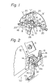
- Figure 1 is a perspective view of an industrial robot provided with a safeguard mechanism according to the present invention
- Fig. 2 is a perspective view of an important portion of the safeguard mechanism according to an embodiment of the present invention.
- the industrial robot has a robot body 10 having a robot casing 12 and a robot base 14.
- the robot casing 12 is pivotable with respect to the robot base 14, as will be described later.
- the industrial robot per se can be mounted on the sides of machines, such as machine tools, by means of the robot base 14. It should therefore be understood that the robot casing 12 is a part of a movable part of the industrial robot.
- On the robot casing 12 is slidably mounted a robot manipulating shaft 16 by means of a slide block 22 so that the robot manipulating shaft 16 is slidable in the direction shown by the arrow "C".
- the robot manipulating shaft 16 is comprised of a robot wrist 18, of which the innermost end is connected to the slide block 22, and a robot hand 20 attached to the outermost end of the robot wrist 18.
- the robot manipulating shaft 16 and the slide block 22 form a part of the movable part of the robot.
- Reference numerals 24, 26, and 28 designate drive motors, respectively, for driving the manipulating operation of the above-mentioned robot movable part, and the drive motors 24, 26, and 28 are driven by command signals fed from a separate robot controller (not illustrated in Fig. 1) so that a controlled manipulating operation of the movable part of the robot is conducted.
- the robot casing 12 is turnable about the axis "A".
- the turning motion of the robot casing 12 is automatically accompanied by the turning motion of the robot manipulating shaft 16 in the direction shown by the arrow "a" between a standing position as shown by the dotted lines and a falling position as shown by the solid lines.
- the industrial robot can perform, for example, the attaching of a workpiece to or the detaching of a workpiece from the machine tool.
- the robot casing 12 is also turnable about the axis "B".
- This turning motion of the robot casing 12 about the axis "B” is automatically accompanied by the turning motion of the robot manipulating shaft 16 in the direction shown by the arrow "b" between the two falling positions shown by the solid lines.
- the industrial robot can, for example, place a workpiece onto a workpiece table (not illustrated in Fig. 1) or remove a workpiece from a workpiece table.
- the robot manipulating shaft 16 is capable of sliding in the direction shown by the arrow "c" when the shaft 16 is in any one of the standing positions or the falling positions.
- the industrial robot can perform diverse kinds of manipulating operations required by machines, such as machine tools.
- machines such as machine tools.
- an operator approaches or comes within the movable range of the movable part of the robot.
- the operator might come close to the spindle of the machine tool for the purpose of setting up the machine tool for work to be subsequently done.
- the operation of the industrial robot is electrically interrupted in the state where the robot manipulating shaft 16 remains in a standing position as shown in Fig. 1.
- the supply of electric power from the elctric power source to the robot is not discontinued.
- a safeguard mechanism capable of mechanically locking the movable part of the industrial robot when an operator approaches or comes within the movable range of the movable part of the robot.
- Figure 2 is a perspective view of the safeguard mechanism according to an embodiment of the present invention and is an important part of the industrial robot.
- the same reference numbers as those in Fig. 1 designate similar robot parts.
- the industrial robot per se is mounted on a stationary base member 50 at a position opposite to a spindle portion S of an associated machine tool M by means of the stationary robot base 14.
- the safeguard mechanism of the embodiment of Fig. 2 is comprised of a rigid pin 30 projecting from a side 12a of the robot casing 12, and a lock plate 40 having a receipt hole 42 into which the rigit pin 30 is engaged when the lock plate 40 is appropriately positioned onto the stationary base member 50.
- the lock plate 40 forms a lock table
- the rigid pin 30 and the receipt hole 42 of the lock plate 40 form a mechanical lock mechanism comprising a pair of male and female engagement means.
- Figure 2 illustrates a state where the male and female engagement means are engaged with one another so as to provide a mechanical lock condition for the movable part of the industrial robot.
- the lock plate 40 may be attached to the stationary base member 50, as required, by means of screw bolt means 44 at the position where the receipt hole 42 is engaged with the rigid pin 30.
- the lock plate 40 may be fixed to a predetermined position on the stationary base member 50 so that the receipt hole 42 of the lock plate 40 is coaxial with the rigid pin 30.
- the lock plate 40 may be arranged so as to be slid on the stationary base member 50 along an appropriate guide until the receipt hole 42 of the lock plate 40 is engaged with the rigid pin 30.
- the L-shaped lock plate 40 is formed as a folding member which can be collapsed at the corner, it will be possible to erect the collapsed lock plate before the receipt hole 42 of the lock plate 40 engages with the rigid pin 30 of the industrial robot.
- the rigid pin 30 is fixedly attached to the movable part of the industrial robot, and the lock plate 40 arranged on the stationary base member 50 is formed with the receipt hole 42.
- the rigid pin 30 may be attached to the lock plate 40, and the side 12a of the robot casing 12 forming a part of the movable part of-the industrial robot may be formed with the receipt hole with which the rigid pin 30 of the lock plate 40 engages as required.
Landscapes
- Engineering & Computer Science (AREA)
- Robotics (AREA)
- Mechanical Engineering (AREA)
- Numerical Control (AREA)
- Manipulator (AREA)
Applications Claiming Priority (2)
| Application Number | Priority Date | Filing Date | Title |
|---|---|---|---|
| JP101225/80 | 1980-07-25 | ||
| JP10122580A JPS5912435B2 (ja) | 1980-07-25 | 1980-07-25 | 工業用ロボットの安全機構 |
Publications (2)
| Publication Number | Publication Date |
|---|---|
| EP0056419A1 true EP0056419A1 (de) | 1982-07-28 |
| EP0056419A4 EP0056419A4 (de) | 1982-11-25 |
Family
ID=14294948
Family Applications (1)
| Application Number | Title | Priority Date | Filing Date |
|---|---|---|---|
| EP19810902242 Withdrawn EP0056419A4 (de) | 1980-07-25 | 1981-07-24 | Sicherheitsmechanismus für industrielle roboter. |
Country Status (3)
| Country | Link |
|---|---|
| EP (1) | EP0056419A4 (de) |
| JP (1) | JPS5912435B2 (de) |
| WO (1) | WO1982000431A1 (de) |
Cited By (1)
| Publication number | Priority date | Publication date | Assignee | Title |
|---|---|---|---|---|
| EP0045513B1 (de) * | 1980-08-05 | 1985-07-24 | Fanuc Ltd. | Industrieroboter mit Sicherheitsmechanismus |
Families Citing this family (1)
| Publication number | Priority date | Publication date | Assignee | Title |
|---|---|---|---|---|
| US4778332A (en) * | 1987-02-09 | 1988-10-18 | The Perkin-Elmer Corporation | Wafer flip apparatus |
Family Cites Families (4)
| Publication number | Priority date | Publication date | Assignee | Title |
|---|---|---|---|---|
| JPS444193Y1 (de) * | 1965-05-19 | 1969-02-17 | ||
| JPS5228881Y2 (de) * | 1972-03-16 | 1977-07-01 | ||
| DE2642910C2 (de) * | 1976-09-24 | 1984-04-26 | Blohm + Voss Ag, 2000 Hamburg | Niederlegbarer Bord-Drehkran |
| JPS5451172A (en) * | 1977-09-29 | 1979-04-21 | Kobe Steel Ltd | Actuator for robot |
-
1980
- 1980-07-25 JP JP10122580A patent/JPS5912435B2/ja not_active Expired
-
1981
- 1981-07-24 WO PCT/JP1981/000168 patent/WO1982000431A1/ja not_active Ceased
- 1981-07-24 EP EP19810902242 patent/EP0056419A4/de not_active Withdrawn
Non-Patent Citations (2)
| Title |
|---|
| None * |
| See also references of WO8200431A1 * |
Cited By (1)
| Publication number | Priority date | Publication date | Assignee | Title |
|---|---|---|---|---|
| EP0045513B1 (de) * | 1980-08-05 | 1985-07-24 | Fanuc Ltd. | Industrieroboter mit Sicherheitsmechanismus |
Also Published As
| Publication number | Publication date |
|---|---|
| JPS5727696A (en) | 1982-02-15 |
| WO1982000431A1 (en) | 1982-02-18 |
| EP0056419A4 (de) | 1982-11-25 |
| JPS5912435B2 (ja) | 1984-03-23 |
Similar Documents
| Publication | Publication Date | Title |
|---|---|---|
| EP0289614B1 (de) | Gerät zur abstimmung der drehungszone von einer drehbaren trommel eines industrieroboters | |
| US4406576A (en) | Industrial robot with a safeguard mechanism | |
| EP0063161A1 (de) | Industrieller roboter | |
| DE102016200887A1 (de) | Werkzeugmaschine | |
| KR102046011B1 (ko) | 다기능 용접 지그 시스템 | |
| KR100264642B1 (ko) | 터릿장치 | |
| EP0044886B1 (de) | Werkzeugmaschine mit automatischer Werkzeugwechselfunktion | |
| EP0868963B1 (de) | Mit dem Werkzeugschlitten einer Werkzeugmaschine wahlweise kuppelbare Kontrolleinheit | |
| KR101675172B1 (ko) | 매니퓰레이터 시스템을 제어하기 위한 방법 및 장치 | |
| EP0056419A1 (de) | Sicherheitsmechanismus für industrielle roboter | |
| EP0254043B1 (de) | Einrichtung und Verfahren zum Bearbeiten von Werkstücken | |
| EP0343315B1 (de) | Sicherheitsvorrichtung für Werkzeuge und Verfahren zum Zusammensetzen | |
| US11806922B2 (en) | CNC machining centre | |
| JP2002187040A (ja) | ローダ制御装置 | |
| EP0066629A1 (de) | Sicherheitsmechanismus für industrielle roboter | |
| EP1157779B1 (de) | Drehantriebssystem für Werkzeugmaschinen | |
| WO2018066590A1 (ja) | ワーク搬送用エンドエフェクタ及びワーク搬送装置 | |
| JP2001246528A (ja) | 工作システム | |
| JP3194219B2 (ja) | トランスファフィーダ装置の同期ズレ解除方法及びその装置 | |
| EP1217479A2 (de) | Steuerungseinheit für Ladung | |
| JPH01205946A (ja) | 数値制御自動旋盤の安全装置 | |
| CN115194807B (zh) | 一种机械手撞击保护系统及方法 | |
| KR100402406B1 (ko) | 안전성을 고려한 축 이송 제어장치 | |
| JPH04105847A (ja) | Nc工作機械の制御装置 | |
| JPH077045Y2 (ja) | 工作機械 |
Legal Events
| Date | Code | Title | Description |
|---|---|---|---|
| PUAI | Public reference made under article 153(3) epc to a published international application that has entered the european phase |
Free format text: ORIGINAL CODE: 0009012 |
|
| 17P | Request for examination filed |
Effective date: 19820322 |
|
| AK | Designated contracting states |
Designated state(s): DE FR GB |
|
| RAP1 | Party data changed (applicant data changed or rights of an application transferred) |
Owner name: FANUC LIMITED |
|
| STAA | Information on the status of an ep patent application or granted ep patent |
Free format text: STATUS: THE APPLICATION IS DEEMED TO BE WITHDRAWN |
|
| 18D | Application deemed to be withdrawn |
Effective date: 19840229 |
|
| RIN1 | Information on inventor provided before grant (corrected) |
Inventor name: SAKAKIBARA, SHINSUKE Inventor name: INABA, HAJIMU Inventor name: NIHEI, RYO Inventor name: KITA, MASAO |