EP0056433B1 - Circuit de lecture pour une mémoire monolithique intégrée semiconductrice - Google Patents
Circuit de lecture pour une mémoire monolithique intégrée semiconductrice Download PDFInfo
- Publication number
- EP0056433B1 EP0056433B1 EP81108510A EP81108510A EP0056433B1 EP 0056433 B1 EP0056433 B1 EP 0056433B1 EP 81108510 A EP81108510 A EP 81108510A EP 81108510 A EP81108510 A EP 81108510A EP 0056433 B1 EP0056433 B1 EP 0056433B1
- Authority
- EP
- European Patent Office
- Prior art keywords
- transistor
- transistors
- flip
- flop
- channel type
- Prior art date
- Legal status (The legal status is an assumption and is not a legal conclusion. Google has not performed a legal analysis and makes no representation as to the accuracy of the status listed.)
- Expired - Lifetime
Links
- 239000004065 semiconductor Substances 0.000 title claims description 3
- 230000005669 field effect Effects 0.000 claims description 9
- 230000000295 complement effect Effects 0.000 claims description 4
- 230000008878 coupling Effects 0.000 claims description 3
- 238000010168 coupling process Methods 0.000 claims description 3
- 238000005859 coupling reaction Methods 0.000 claims description 3
- 230000015572 biosynthetic process Effects 0.000 claims 1
- 230000002123 temporal effect Effects 0.000 claims 1
- 230000015654 memory Effects 0.000 description 38
- 239000011159 matrix material Substances 0.000 description 12
- 230000004888 barrier function Effects 0.000 description 2
- 239000003990 capacitor Substances 0.000 description 2
- 238000010586 diagram Methods 0.000 description 2
- 230000000694 effects Effects 0.000 description 2
- 238000005516 engineering process Methods 0.000 description 2
- 230000004044 response Effects 0.000 description 2
- 230000035945 sensitivity Effects 0.000 description 2
- 230000008901 benefit Effects 0.000 description 1
- 238000006880 cross-coupling reaction Methods 0.000 description 1
- 230000001419 dependent effect Effects 0.000 description 1
- 238000011161 development Methods 0.000 description 1
- 230000018109 developmental process Effects 0.000 description 1
- 238000004519 manufacturing process Methods 0.000 description 1
- 230000008520 organization Effects 0.000 description 1
Images

Classifications
-
- G—PHYSICS
- G11—INFORMATION STORAGE
- G11C—STATIC STORES
- G11C11/00—Digital stores characterised by the use of particular electric or magnetic storage elements; Storage elements therefor
- G11C11/21—Digital stores characterised by the use of particular electric or magnetic storage elements; Storage elements therefor using electric elements
- G11C11/34—Digital stores characterised by the use of particular electric or magnetic storage elements; Storage elements therefor using electric elements using semiconductor devices
- G11C11/40—Digital stores characterised by the use of particular electric or magnetic storage elements; Storage elements therefor using electric elements using semiconductor devices using transistors
- G11C11/401—Digital stores characterised by the use of particular electric or magnetic storage elements; Storage elements therefor using electric elements using semiconductor devices using transistors forming cells needing refreshing or charge regeneration, i.e. dynamic cells
- G11C11/4063—Auxiliary circuits, e.g. for addressing, decoding, driving, writing, sensing or timing
- G11C11/407—Auxiliary circuits, e.g. for addressing, decoding, driving, writing, sensing or timing for memory cells of the field-effect type
- G11C11/409—Read-write [R-W] circuits
- G11C11/4091—Sense or sense/refresh amplifiers, or associated sense circuitry, e.g. for coupled bit-line precharging, equalising or isolating
Definitions
- the invention relates to a reading shaft in a monolithically integrated semiconductor memory according to the preamble of claim 1.
- a read circuit is known from JP-A-5 354 430, which is constructed as a pure n-channel circuit. It contains two cross-coupled transistors, two clocked shaft devices for supplying supply potentials, two barrier transistors for coupling the read circuit to bit line sections and a transistor for charge equalization between the bit line sections.
- the switching devices for supplying the supply potentials are activated at different times.
- the transistor for charge equalization is activated precisely when the one supply potential is applied to the read circuit.
- the gates of the barrier transistors are obviously connected to a fixed potential.
- each column of the memory matrix is assigned a comparator which acts as a differential amplifier and is located in the middle of the column in question and is given by a bistable flip-flop.
- One half of the one-transistor memory cells provided for each column is connected with its drain connection to one input and the other half in the same way to the other input of the comparator.
- two comparison cells, so-called dummy cells are provided in each column, which are connected to one of the two inputs of the associated comparator in the same way as the actual memory cells.
- each bit line BL of the memory matrix is halved and half is connected to one signal input and the other half to the other signal input of the respective comparator K .
- the number of one-transistor memory cells provided per column is accordingly also halved, with one half lying on one and the other half on the other signal input of the comparator K, as can also be seen from FIG. 1, which will still be described.
- the voltage-carrying connection of the MOS transistor of the individual one-transistor memory cell facing away from the relevant bit line BL is connected to the reference potential (ground) via the storage capacitor of the relevant cell or instead to the other operating potential (Vcc).
- Such a memory circuit is e.g. B. in "1978 IEEE International Solid-State Circuits Conference", pp. 156 and 157, (see, for example, Fig. 1 in this reference).
- the comparator K is generally made up of transistors of the same type as is used for the transistors of the one-transistor memory cells.
- the comparator K can therefore be produced together with the other transistors of the memory without additional doping.
- CMOS memories were known (cf. proc. IEEE (July 1971), pp. 1044-1058; in particular pp. 1054, Fig. 17), which use so-called six-transistor cells as memory cells.
- These memory cells are each composed of two inverters designed using CMOS technology, which in turn consist of the series shading of a p-channel transistor and an n-channel transistor (both of the enhancement type).
- the gates of these two complementary MOS transistors of the individual inverter together form the signal input of the inverter, while its signal output is given by a circuit point between the series-source-drain paths of the two transistors of the inverter.
- the two inverters are now z. B.
- the two gates of the first inverter are at the signal output of the second inverter and the two gates of the second inverter of the memory cell are at the signal output of the first inverter, as a result of which the desired flip-flop effect and thus the storage capacity of the cell are determined.
- connections of the cell given by the outputs of the two inverters via the source-drain path each of an n-channel MOS field-effect transistor of the enhancement type are connected to one of the bit lines controlling the flip-flop memory cell in question is, while the gates of these two field effect transistors are controlled via the word line assigned to the relevant memory cell.
- the object of the present invention is to be seen in improving the dynamic matrix memories based on one-transistor memory cells with regard to the sensitivity of the response by increasing the efficiency of its comparators.
- FIGS. 1 to 3. show two preferred embodiments to be used and in FIG. 3 the associated time diagram.
- the one-transistor memory cells used in the configurations in FIGS. 1 and 2 consist, as already indicated, of a transfer transistor t s , the drain of which is connected to the reference potential via the storage capacitor C s assigned to the memory cell in question, while its source connection is connected to the bit line BL assigned to the respective matrix column and thus to the respective memory cell.
- the charge transistors or transfer transistors t s usually consist of mutually identical n-channel MOS-FETs of the enhancement type and are therefore self-blocking. The latter incidentally applies to all field effect transistors used in the memory matrix including the comparators K.
- the number of memory cells assigned to the individual matrix spaces is halved, so that one half of these memory cells t s , C s via one half of the respectively assigned Birt réelle BL with the information-carrying connection a and the other half of these memory cells via the other Half of the bit line BL is connected to the other information-carrying connection b of the comparator K.
- the gates of the one-transistor memory cells respectively assigned to the individual matrix row, ie their transistors t s are each connected to a common word line WL and are addressed via this. In contrast to the bit lines BL, the word lines WL are not halved for obvious reasons.
- each half of the bit lines BL is provided with a comparison cell or dummy cell to, C D which corresponds to the individual one-transistor memory cells t s , Cs, and which is connected to the associated bit line half BL in the same way as the actual memory cells.
- C D is located at each of the two information-carrying connections a and b of the comparators K provided.
- the comparison cells connected to the connections a of the comparators K can be addressed via a first dummy line DL corresponding to the word lines in the actual memory cells t s , Cs, and the comparison cells connected to the connections b of the comparators K can be addressed by an analog second dummy line DL .
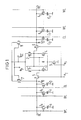
- the source-drain path of an n-channel field-effect transistor 5 or 6 leads into the interior of the comparator K.
- the other current-carrying connection of these two n-channel transistors 5 and 6 is connected to the output of the CMOS inverter 1, 3 and the input of the CMOS inverter 2, 4 or to the output of the CMOS inverter 2, 4 and the input of the CMOS inverter 1, 3.
- the two MOS field-effect transistors 5 and 6 are controlled by a common clock signal ⁇ and can optionally also be implemented as p-channel MOS-FETs.
- the structure of the two inverters 1, 3 and 2, 4 corresponds to the known CMOS memory cells, the two transistors 1 and 2 being of the p-channel type and the two transistors 3 and 4 being of the n-channel type in the example. Both transistors 1 and 2 on the one hand and both transistors 3 and 4 are each connected to one another via their source connections and are acted upon via these by one of the two operating potentials Vcc or the reference potential (ground) provided for the circuit.
- the drains of the two transistors 1 and 3 are connected on the one hand via the n-channel transistor 5 to the information-carrying connection a and the drains of the two transistors 2 and 4 on the other hand via the n-channel transistor to the information-carrying connection b of the comparator K.
- cross-coupling is provided in that the drains of transistors 2 and 4 are connected to the gates of transistors 1 and 3 and the drains of transistors 1 and 3 are connected to the gates of transistors 2 and 4.
- FIG. 1 and FIG. 2 still have in common that between the supply connection supplying the reference potential, that is to say the source connections of the two n-channel transistors 3 and 4 of the comparator K, the source-drain path of a further n-channel MOS-FET 9 is laid. This is controlled by a further clock signal ⁇ s .
- the two information-carrying connections a and B of the comparator K are connected to one another via the series connection of two p-channel MOS-FETs 7 and 8.
- the gates of these two transistors 7 and 8 are controlled together by a third clock signal p.
- the supply terminal supplying the first operating potential Vcc is located both at the source terminals of the two p-channel transistors 1 and 2 of the flip-flop of the comparator K and also at a circuit point between the source-drain paths of the two p-channel transistors 7 and 8 connected in series, as can be seen from Fig. 1.
- bit lines BL are obviously precharged to the Vcc potential.
- an embodiment can also be of interest in which the bit lines are precharged to the potential 1 / 2Vcc.
- the switching mode shown in FIG. 2 is the case with the switching mode shown in FIG. 2.
- a single MOS-FET 11 is provided in the connection between the two information-carrying connections a and b of the comparator K, which is also of the p-channel type and has a clock signal ⁇ p , is controlled, which corresponds to the clock signal ⁇ p to be used for controlling the p-channel transistors 7 and 8 in a circuit according to FIG. 1.
- the first operating potential Vcc is also not applied directly to the flip-flop 1, 2, 3 and 4 forming the comparator K. Rather, in deviation from FIG.
- a switching transistor 10 is also provided here corresponding to the switching transistor 9, which, however, in contrast to the switching transistor 9, is of the p-channel type and is controlled by a clock signal which inverts to the clock signal ⁇ s controlling the transistor 9 and therefore is denoted by ⁇ s .
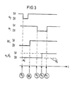
- the timing diagram for the clock control of the comparator K is shown in FIG.
- the pulses ⁇ S , ⁇ T , ⁇ P and WL are clock pulses that are also used in the operation of the known dynamic RAM memories.
- the pulse train ⁇ s is used to activate the comparator K and the pulse train ⁇ T to disconnect or connect the bit lines BL to the comparator K, the pulse train ⁇ P to precharge the bit lines BL and the pulse train WL to control the word lines.
- the signal ⁇ s provided in a circuit according to FIG. 2 for controlling the switching transistor 10 and inverted to signal ⁇ s.
- the two switching transistors 9 and 10 can simultaneously be assigned to a plurality of comparators K and thus to matrix columns at the same time, so that simplification and thus space saving is also possible in this regard. It should also be noted that, in an arrangement according to the invention, the totality of the memory cells t s , Cs provided per column only at the same input of the comparator K, e.g. B. can be switched on at input a, so that only the dummy cell assigned to the relevant column is connected to the other input b.
Landscapes
- Engineering & Computer Science (AREA)
- Microelectronics & Electronic Packaging (AREA)
- Computer Hardware Design (AREA)
- Static Random-Access Memory (AREA)
- Read Only Memory (AREA)
- Dram (AREA)
Claims (3)
Applications Claiming Priority (2)
| Application Number | Priority Date | Filing Date | Title |
|---|---|---|---|
| DE3101520 | 1981-01-19 | ||
| DE19813101520 DE3101520A1 (de) | 1981-01-19 | 1981-01-19 | Monolithisch integrierter halbleiterspeicher |
Publications (3)
| Publication Number | Publication Date |
|---|---|
| EP0056433A2 EP0056433A2 (fr) | 1982-07-28 |
| EP0056433A3 EP0056433A3 (en) | 1985-10-30 |
| EP0056433B1 true EP0056433B1 (fr) | 1990-01-17 |
Family
ID=6122891
Family Applications (1)
| Application Number | Title | Priority Date | Filing Date |
|---|---|---|---|
| EP81108510A Expired - Lifetime EP0056433B1 (fr) | 1981-01-19 | 1981-10-19 | Circuit de lecture pour une mémoire monolithique intégrée semiconductrice |
Country Status (5)
| Country | Link |
|---|---|
| US (1) | US4441171A (fr) |
| EP (1) | EP0056433B1 (fr) |
| JP (1) | JPS57138090A (fr) |
| DE (2) | DE3101520A1 (fr) |
| HK (1) | HK76192A (fr) |
Families Citing this family (17)
| Publication number | Priority date | Publication date | Assignee | Title |
|---|---|---|---|---|
| JPS57186289A (en) * | 1981-05-13 | 1982-11-16 | Hitachi Ltd | Semiconductor memory |
| US5119332A (en) * | 1981-05-13 | 1992-06-02 | Hitachi, Ltd. | Semiconductor memory |
| FR2528613B1 (fr) * | 1982-06-09 | 1991-09-20 | Hitachi Ltd | Memoire a semi-conducteurs |
| JPS5956292A (ja) * | 1982-09-24 | 1984-03-31 | Hitachi Ltd | 半導体記憶装置 |
| US4572506A (en) * | 1983-06-03 | 1986-02-25 | Commodore Business Machines | Raster line comparator circuit for video game |
| JPS6010495A (ja) * | 1983-06-30 | 1985-01-19 | Fujitsu Ltd | センスアンプ |
| US4551641A (en) * | 1983-11-23 | 1985-11-05 | Motorola, Inc. | Sense amplifier |
| JPS6122494A (ja) * | 1984-07-10 | 1986-01-31 | Nec Corp | アクテイブプルアツプ回路 |
| US4656612A (en) * | 1984-11-19 | 1987-04-07 | Inmos Corporation | Dram current control technique |
| JPS61158094A (ja) * | 1984-12-28 | 1986-07-17 | Toshiba Corp | ダイナミツク型メモリのセンスアンプ駆動回路 |
| US4651305A (en) * | 1985-02-11 | 1987-03-17 | Thomson Components-Mostek Corporation | Sense amplifier bit line isolation scheme |
| US4791616A (en) * | 1985-07-10 | 1988-12-13 | Fujitsu Limited | Semiconductor memory device |
| JPH0642537B2 (ja) * | 1985-11-15 | 1994-06-01 | 株式会社東芝 | 半導体装置 |
| JPS63146612A (ja) * | 1986-12-10 | 1988-06-18 | Mitsubishi Electric Corp | トグルフリツプフロツプ回路 |
| JPH0799627B2 (ja) * | 1987-01-23 | 1995-10-25 | 松下電器産業株式会社 | 半導体メモリの書き込み読み出し回路 |
| US4804871A (en) * | 1987-07-28 | 1989-02-14 | Advanced Micro Devices, Inc. | Bit-line isolated, CMOS sense amplifier |
| JPH02312097A (ja) * | 1989-05-26 | 1990-12-27 | Nec Corp | センスアンプ駆動方式 |
Family Cites Families (8)
| Publication number | Priority date | Publication date | Assignee | Title |
|---|---|---|---|---|
| US3879621A (en) * | 1973-04-18 | 1975-04-22 | Ibm | Sense amplifier |
| DE2634089C3 (de) * | 1975-08-11 | 1988-09-08 | Nippon Telegraph And Telephone Corp., Tokio/Tokyo | Schaltungsanordnung zum Erfassen schwacher Signale |
| JPS52113131A (en) * | 1975-09-08 | 1977-09-22 | Toko Inc | Sensing amplifier for one transistor |
| JPS54112131A (en) * | 1978-02-23 | 1979-09-01 | Nec Corp | Sense amplifier circuit of mos memory |
| US4169233A (en) * | 1978-02-24 | 1979-09-25 | Rockwell International Corporation | High performance CMOS sense amplifier |
| US4195357A (en) * | 1978-06-15 | 1980-03-25 | Texas Instruments Incorporated | Median spaced dummy cell layout for MOS random access memory |
| US4255679A (en) * | 1978-10-30 | 1981-03-10 | Texas Instruments Incorporated | Depletion load dynamic sense amplifier for MOS random access memory |
| JPS5694574A (en) * | 1979-12-27 | 1981-07-31 | Toshiba Corp | Complementary mos sense circuit |
-
1981
- 1981-01-19 DE DE19813101520 patent/DE3101520A1/de not_active Withdrawn
- 1981-10-19 EP EP81108510A patent/EP0056433B1/fr not_active Expired - Lifetime
- 1981-10-19 DE DE8181108510T patent/DE3177149D1/de not_active Expired - Lifetime
-
1982
- 1982-01-13 JP JP57003977A patent/JPS57138090A/ja active Pending
- 1982-01-13 US US06/339,156 patent/US4441171A/en not_active Expired - Lifetime
-
1992
- 1992-10-01 HK HK761/92A patent/HK76192A/xx not_active IP Right Cessation
Also Published As
| Publication number | Publication date |
|---|---|
| EP0056433A3 (en) | 1985-10-30 |
| DE3177149D1 (de) | 1990-02-22 |
| US4441171A (en) | 1984-04-03 |
| DE3101520A1 (de) | 1982-08-26 |
| JPS57138090A (en) | 1982-08-26 |
| EP0056433A2 (fr) | 1982-07-28 |
| HK76192A (en) | 1992-10-09 |
Similar Documents
| Publication | Publication Date | Title |
|---|---|---|
| EP0056433B1 (fr) | Circuit de lecture pour une mémoire monolithique intégrée semiconductrice | |
| DE2912320C2 (de) | Leseverstärker | |
| DE2650479C2 (de) | Speicheranordnung mit Ladungsspeicherzellen | |
| DE3882278T2 (de) | MOS-Speicher. | |
| DE68917609T2 (de) | Schaltung zum Treiben eines Dekodierers für Programmierung von hochkapazitiven Zeilen. | |
| DE69819278T2 (de) | Integrierte Halbleiterschaltung mit logischem Gatter mit drei Betriebszuständen | |
| DE3942386C2 (de) | Zeitgabeschaltung für einen Halbleiterspeicher | |
| DE2548564A1 (de) | Halbleiterspeicher mit wahlfreiem zugriff | |
| DE2324965A1 (de) | Schaltungsanordnung zum auslesen eines kapazitiven datenspeichers | |
| DE4036091A1 (de) | Halbleiterspeicheranordnung mit einem in eine anzahl von zellenbloecken unterteilten zellenarray | |
| DE2324769C3 (de) | Steuerschaltung für einen Datenspeicher mit IG-FET's | |
| DE69123409T2 (de) | Halbleiterspeicherschaltung | |
| DE2556831A1 (de) | Matrixspeicher und verfahren zu seinem betrieb | |
| DE3206507C2 (fr) | ||
| DE2608119A1 (de) | Schaltkreis zum abtasten und auffrischen eines halbleiterspeichers | |
| DE3236729C2 (fr) | ||
| DE69112692T2 (de) | Dynamische Direktzugriffspeicheranordnung mit verbesserter Speisespannung für eine beschleunigte Wiedereinschreibung von von Speicherzellen gelesenen Informationsbits. | |
| DE3514252A1 (de) | Halbleiterspeichervorrichtung | |
| DE3786382T2 (de) | Halbleiterspeicheranordnung mit Datenbusrücksetzungsschaltungen. | |
| DE2845100A1 (de) | Speicherschaltung | |
| DE4211843C2 (de) | Halbleiterspeichervorrichtung | |
| DE3430145C2 (de) | Halbleiter-Speichereinrichtung | |
| DE2128792A1 (de) | Schaltungsanordnung mit mindestens einem Feldeffekttransistor | |
| DE3430144A1 (de) | Halbleiter-speichereinrichtung | |
| EP0045020A2 (fr) | Amplificateur de lecture dynamique pour des mémoires à semiconducteur MOS |
Legal Events
| Date | Code | Title | Description |
|---|---|---|---|
| PUAI | Public reference made under article 153(3) epc to a published international application that has entered the european phase |
Free format text: ORIGINAL CODE: 0009012 |
|
| 17P | Request for examination filed |
Effective date: 19811019 |
|
| AK | Designated contracting states |
Designated state(s): DE FR GB |
|
| PUAL | Search report despatched |
Free format text: ORIGINAL CODE: 0009013 |
|
| AK | Designated contracting states |
Designated state(s): DE FR GB |
|
| 17Q | First examination report despatched |
Effective date: 19870514 |
|
| GRAA | (expected) grant |
Free format text: ORIGINAL CODE: 0009210 |
|
| AK | Designated contracting states |
Kind code of ref document: B1 Designated state(s): DE FR GB |
|
| REF | Corresponds to: |
Ref document number: 3177149 Country of ref document: DE Date of ref document: 19900222 |
|
| ET | Fr: translation filed | ||
| GBT | Gb: translation of ep patent filed (gb section 77(6)(a)/1977) | ||
| PLBE | No opposition filed within time limit |
Free format text: ORIGINAL CODE: 0009261 |
|
| STAA | Information on the status of an ep patent application or granted ep patent |
Free format text: STATUS: NO OPPOSITION FILED WITHIN TIME LIMIT |
|
| 26N | No opposition filed | ||
| PGFP | Annual fee paid to national office [announced via postgrant information from national office to epo] |
Ref country code: GB Payment date: 20001012 Year of fee payment: 20 |
|
| PGFP | Annual fee paid to national office [announced via postgrant information from national office to epo] |
Ref country code: FR Payment date: 20001027 Year of fee payment: 20 |
|
| PGFP | Annual fee paid to national office [announced via postgrant information from national office to epo] |
Ref country code: DE Payment date: 20001218 Year of fee payment: 20 |
|
| PG25 | Lapsed in a contracting state [announced via postgrant information from national office to epo] |
Ref country code: GB Free format text: LAPSE BECAUSE OF EXPIRATION OF PROTECTION Effective date: 20011018 |
|
| REG | Reference to a national code |
Ref country code: GB Ref legal event code: PE20 Effective date: 20011018 |