EP0056478A1 - Process for electrolytically colouring a piece of aluminium or aluminium alloy - Google Patents
Process for electrolytically colouring a piece of aluminium or aluminium alloy Download PDFInfo
- Publication number
- EP0056478A1 EP0056478A1 EP81110658A EP81110658A EP0056478A1 EP 0056478 A1 EP0056478 A1 EP 0056478A1 EP 81110658 A EP81110658 A EP 81110658A EP 81110658 A EP81110658 A EP 81110658A EP 0056478 A1 EP0056478 A1 EP 0056478A1
- Authority
- EP
- European Patent Office
- Prior art keywords
- colouring
- phase
- conduction
- piece
- alternating current
- Prior art date
- Legal status (The legal status is an assumption and is not a legal conclusion. Google has not performed a legal analysis and makes no representation as to the accuracy of the status listed.)
- Granted
Links
- 238000000034 method Methods 0.000 title claims abstract 9
- 238000004040 coloring Methods 0.000 title claims abstract 7
- 229910000838 Al alloy Inorganic materials 0.000 title claims abstract 4
- 239000004411 aluminium Substances 0.000 title claims abstract 4
- 229910052782 aluminium Inorganic materials 0.000 title claims abstract 4
- XAGFODPZIPBFFR-UHFFFAOYSA-N aluminium Chemical compound [Al] XAGFODPZIPBFFR-UHFFFAOYSA-N 0.000 title claims abstract 4
- 229910052751 metal Inorganic materials 0.000 claims abstract 6
- 239000002184 metal Substances 0.000 claims abstract 6
- 150000003839 salts Chemical class 0.000 claims abstract 6
- 230000000694 effects Effects 0.000 claims abstract 4
- 239000003792 electrolyte Substances 0.000 claims abstract 4
- 239000002253 acid Substances 0.000 claims abstract 2
- 238000004090 dissolution Methods 0.000 claims abstract 2
- 239000000126 substance Substances 0.000 claims abstract 2
- 230000001960 triggered effect Effects 0.000 claims 2
- 238000002048 anodisation reaction Methods 0.000 claims 1
- 230000002457 bidirectional effect Effects 0.000 claims 1
- 230000003647 oxidation Effects 0.000 claims 1
- 238000007254 oxidation reaction Methods 0.000 claims 1
- QAOWNCQODCNURD-UHFFFAOYSA-N Sulfuric acid Chemical compound OS(O)(=O)=O QAOWNCQODCNURD-UHFFFAOYSA-N 0.000 abstract 1
- 230000001747 exhibiting effect Effects 0.000 abstract 1
- 235000011149 sulphuric acid Nutrition 0.000 abstract 1
Images


Classifications
-
- C—CHEMISTRY; METALLURGY
- C25—ELECTROLYTIC OR ELECTROPHORETIC PROCESSES; APPARATUS THEREFOR
- C25D—PROCESSES FOR THE ELECTROLYTIC OR ELECTROPHORETIC PRODUCTION OF COATINGS; ELECTROFORMING; APPARATUS THEREFOR
- C25D11/00—Electrolytic coating by surface reaction, i.e. forming conversion layers
- C25D11/02—Anodisation
- C25D11/04—Anodisation of aluminium or alloys based thereon
- C25D11/18—After-treatment, e.g. pore-sealing
- C25D11/20—Electrolytic after-treatment
- C25D11/22—Electrolytic after-treatment for colouring layers
-
- Y—GENERAL TAGGING OF NEW TECHNOLOGICAL DEVELOPMENTS; GENERAL TAGGING OF CROSS-SECTIONAL TECHNOLOGIES SPANNING OVER SEVERAL SECTIONS OF THE IPC; TECHNICAL SUBJECTS COVERED BY FORMER USPC CROSS-REFERENCE ART COLLECTIONS [XRACs] AND DIGESTS
- Y10—TECHNICAL SUBJECTS COVERED BY FORMER USPC
- Y10S—TECHNICAL SUBJECTS COVERED BY FORMER USPC CROSS-REFERENCE ART COLLECTIONS [XRACs] AND DIGESTS
- Y10S204/00—Chemistry: electrical and wave energy
- Y10S204/09—Wave forms
-
- Y—GENERAL TAGGING OF NEW TECHNOLOGICAL DEVELOPMENTS; GENERAL TAGGING OF CROSS-SECTIONAL TECHNOLOGIES SPANNING OVER SEVERAL SECTIONS OF THE IPC; TECHNICAL SUBJECTS COVERED BY FORMER USPC CROSS-REFERENCE ART COLLECTIONS [XRACs] AND DIGESTS
- Y10—TECHNICAL SUBJECTS COVERED BY FORMER USPC
- Y10S—TECHNICAL SUBJECTS COVERED BY FORMER USPC CROSS-REFERENCE ART COLLECTIONS [XRACs] AND DIGESTS
- Y10S205/00—Electrolysis: processes, compositions used therein, and methods of preparing the compositions
- Y10S205/917—Treatment of workpiece between coating steps
Definitions
- the present invention relates to an electrolitic colouring process for the production of coloured aluminium or aluminium alloy pieces useful in architecture and provided with a surface coating which conforms to the regulations for granting the quality mark EURAS EWAA (European Anodizers and European Wrought Aluminium Association).
- EURAS EWAA European Anodizers and European Wrought Aluminium Association
- the formation of the porous aluminium oxide film on the said metal and its alloys is due to the simultaneous oxidation and dissolution action of the electrolyte. It is also known that the oxidation is conditioned by the electric parameters and by the conductivity of the electrolyte, whilst the dissolution is directly related with the concentration and the temperature of the elctrolyte, which temperature depends, in its turn, on the electric energy generated by the Joule effect.
- the values of said parameters such as: concentration, current density, voltage, conductivity, temperature,efficiency of the dissipation of the heat produced by the Joule effect, uniformity of the distribution of the current on the charge to be anodized, etc., have to be maintained within within precise limits.
- an electrolyte is used, preferably an acid which contains one or more metal salts similar to those used in the electrolytes used in the electrodeposition processes.
- an alternating current By applying an alternating current a deposition of the metal corresponding to the cation(s) of the salts present in the electrolyte is produced.
- These deposited metal particles are the cause of the subsequent colouring. Said deposition takes place under a surprising form, because, as is known, if an alternating current is emplyed in a conventional electrideposition process, the electrodeposition will not be achieved because, obviously, the deposition produced during the phase in which the piece has a negative polarity will dissolve in the phase of opposite polarity.
- the non porous layer 6f the anodic film (commonly called barrier layer or dielect ric layer) is of semiconductor nature, in the sense that it allows a greater passage of current when the polarity of the piece of aluminium is nagative. This enhances the effect of deposition relative to the effect of dissolution, the result being the production of a deposit of metal particles.
- the process would require an increase of the voltage applied in order to enhance the deposition in said more remote portions.
- protons having the same charge as the metal cations and with a greater mobility than these latter.
- the deposition of said protons gives rise to the formation of nascent hydrogen which tends to dissolve the barrier layer thus reducing its thickness with the resulting danger of weakening also the anchorage of the anodic film on the base metal, even up to such limits which may give rise to the spalling of the anodic layer.
- the present invention provides another electric diagram representative for the piece to be coloured, which wiring diagram is shown in Fig. 1 of the accompanying drawings.
- R e indicates the- electric resistance of the electrolyte
- C is the capacity due to the barrier film
- R p is the electric resistance imputable to the porosity of the anodic fil
- R A and R B represent the electric resistances to the passage of the current through the barrier layer in both directions of circulation of the current, these resistances being different owing to the semiconductor nature of the barrier layer.
- anodization phase a) any of the usual techinques may be used, without any limitation. It will be appreciated that said anodization phase a) does not form part of the novelty characteristics recited in the annexed Claims.
- an electrolyte of low dissolution capacity substantially formed by sulphuric acid at a concentration of less than 4 g/1 or by another acid which provides an equivalent - concentration of protons H + for the case of the electrolyte utilized in the subsequent colouring phase c) being incompatible with the sulphuric acid.
- a measure of the impedance of the charge is obtained, which serves as reference for determining the conditions of the current to be applied in the subsequent colouring phase. This refernce is applied automatically in the colouring phase, in the case of using a programming by means of a microprocessor.
- Another characteristic of the pre-colouring phase b) of the process according to the present invention consists in . carrying out these phasesby means of an alternating current with a peak voltage from 55 to 85 volt and a current density of less than 0,3 Amp/dm 2 .
- the last phase c) of the process of the present invention consists in carrying out the colouring of pieces previously treated in the phase b), by means of electrodeposition in an electrolyte formed by a sulphuric acid electrolyte and a compound of a metal selected from nickel, cobalt, copper, tin,cadmium or their alloys, by application of an alternating current with a peak voltage of the same range as that applied in the pre-colouring phase, i.e; from to 55 to 85 volts.
- alternating supply source of the electrolytic vessel in this or other similar process a polyphase network is used which is connected directly or through a transformer to an electronic device which controls the conducting periods.
- the electronic device used as compared with the known devices, has the advantage of absorbing energy equally for each of the phases of the polyphase system, so that the electric supply network remains equilibrated.
- the prior art processes utilize as alternating voltage source a one-phase line, a phase of. a polyphase system, a polyphase line with a transformer polyphase in the primary and one-phase in the depoty or other more sophisticatedprocesses, but with the disadvantage, except the one-phase network, of giving rise to considerable unbalances in the phases of the energy distribution systems, so that the advantages which a polyphase network offers to each user of electric energy are reduced and the saving possibilities obtainable by a polyphase supply are not achieved by the conventional supply systems.
- the present inventiobn by using practically the same means which are utilized in the conventional methods, ensures the obtainement from a polyphase electric supply a source of alternating supply with a control of the angle of conduction, which charges equally the three phases of the polyphase system, no matter how many phases it is made of, not only maintaining the possibilities of the conventional systems, but also permitting all the modalities which are offered by control of the division of the phases.
- Fig. 2 shows on a diagram of waves of a six-phase system the cycles of conduction to which the present invention relates; the first, second and third phases are indicated by A, B and C rispectively, whilst the cycles of conduction of the fourth, fifth and sixth phases are not shown, their representation being unnecessary.
- Fig. 2 there is indicated the angle of non-conduction , which is a secondary consequence of the process.
- the value of t is 360/n; the higher the number of phases of the system, the smaller is ; accordingly, in a system with a high number of phases the resulting wave is the most similar to that which is produced by a one-phase system, but with the advantage of utilizing as electric energy source a polyphase system.
- Fig. 3 shows shows on the same six-phase diagram of waves shown in Fig. 2, the result of controlling the angle conduction ⁇ in order to obtain an alternating voltage with effective value as a function of the said angle ⁇ .
- Figures 6, 7, 8 and 9 represent the symbols of the devices E shown in Figures 4 and 5:, which symbols indicate the tyristors, the triac and the combination of rectifiers and transistors, respectively.
- thyristors or controlled rectifiers connected in parallel and with inverted polarity allows, by acting on tha gates of both components, to select the necessary cycle of conduction and the angle of conduction for obtaining the division of the charges in the polyphase system and the angle of conduction corresponding to the efficient value of the alternating voltage applied in the electro-chemical process.
- triacs allcws the same operating operations as the thyristors, but the instruction of control of the cycle and the angle of conduction is supplied to a single gate, this being is the characteristic of this component.
- transistors allow, besides the possibilities mentioned for the thyristors and the triacs, to control an angle of conduction with completely determined beginning and end as shown in Fig. 10, but obviously with trigger circuits different from those for the thyristors and the triacs; in this way an optimization of the efficiency is obtained when using the wave zone of maximum energy.
- the thyristors in parallel and inverted connection, the triac and the assembly of transistors and rectifiers operate by means of suitable instructions from control trigger circuits, as rectifier assemblies with control of the angle of conduction; in this way, onto the electrolytic vessel there is applied a pulsating direct voltage of variable efficient value, which is utilized to achieve an electrolytic decolorization in case an excess of colouring has been produced in the preceding process.
- Fig. 11 The rectifier wave in the cases of control by thyristors in antiparallel or triacs is shown in Fig. 11 on a diagram, as those shown in the preceding Figures, of a six-phase system.
- Fig. 12 represents the waveform when using transistors; in this case the transistor T2 shown in Fig. 8 would cease conducting,as well as the transistors TR1 and TR2 shown in Fig. 9, for attaining this purpose.
- the processing of the trigger instructions S .shown in Figures 4 and 5 for controlling the commutation.-of the phase circulation,the angles of circulation and the operation of the source as a rectifier; is obtainable by known multiple 'electronic means.
- the use of microprocessors allows, by means of some programs to be utilized in each electrochemical proces, to make the source operate in any of the ways indicated, in a completely automatic manner and with a with a control of the commutation of the phases and very precise angles of conduction.
- the programms-necessary in each process are registered in the memory of the microprocessor which allows a very large variety of the same.
- the electronic device described hereinabove in relation to the electrolytic - colouring of pieces of aluminium or aluminium alloys may be applied in other industrial fields in which an unbalancing of phases is produced, as for example in the distribution of current for electric illumination, systems of electric supply for railway, etc.
- An aluminium section is submitted to preliminary anodization by means of a bath of sulphuric acid having a concentration of 180 g/l, at a temperature of 20°C, under a current density of -1,5 Amp/dm 2 and for a period of time of 35 minutes.
- the resulting anodized piece is submitted to the phases of the porcesso of the present invention, in the following way:
- the anodized piece is treated in a bath composed of sulphuric acid (2 g/1) and citric acid (13 g/1), by applying an alternating current with a peak voltage of 62 volt for 3 minutes, with a current density of 0,25 A mp/dm 2 .
- the piece resulting from the preceding operation is submitte to electrolitic colouring in a bath composed of: by applying an alternating current with a peak voltage of 65 volt and a current density of 0,25 Amp/dm 2 ; in order to obtain the following colours in the indicated periods of time:
- Example 1 The preliminary anodization of Example 1 is repeated and thereafter the anodized piece is submitted to the phases of pre-colouring and colouring according to the present invention, under the following conditions:
- the pre-colouring bath is composed of sulphuric acid having a concentration of 4 g/l.
- the alternating current is applied with a peak voltage of 65 volts, at a current density of 0,28 Amp/dm 2 , for two minutes.
- 2.- Colouring phase :
- the colouring bath is composed of CuSO 4 with a concentration of 20 g/l of H 2 SO 4 in a quantity sufficient for maintaining in the bath a pH of 1,1. Alternating current is applied at a peak voltage of 70 volts at a current density of 0,32 Amp/dm 2 , to obtain the following colours in the indicated periods of time:
- Example 1 The preliminary anodization of Example 1 is repeated and thereafter the anodized piece is submitted to the phases of pre-colouring and colouring according to the present invention:
- the piece is treated in a bath composed of sulphuric acid (3 g/1) and citric acid (20 g/l), by applying an alternating current at a peak voltage of 70 volts, at a current density of 0,27 Amp/dm 2 , for 2,5 minutes.
- the treatment bath is composed of:
- Alternating current is applied at peak voltage of 70 volts at a current density of 0,34 Amp/dm 2 , to obtain the following colours in the indicated periods of time:
Landscapes
- Chemical & Material Sciences (AREA)
- Engineering & Computer Science (AREA)
- Chemical Kinetics & Catalysis (AREA)
- Electrochemistry (AREA)
- Materials Engineering (AREA)
- Metallurgy (AREA)
- Organic Chemistry (AREA)
- Prevention Of Electric Corrosion (AREA)
- Printing Plates And Materials Therefor (AREA)
- Electroplating Methods And Accessories (AREA)
- Electrochromic Elements, Electrophoresis, Or Variable Reflection Or Absorption Elements (AREA)
- Electrochemical Coating By Surface Reaction (AREA)
- Laminated Bodies (AREA)
- Forging (AREA)
- Sealing Material Composition (AREA)
- Lubricants (AREA)
Abstract
Description
- The present invention relates to an electrolitic colouring process for the production of coloured aluminium or aluminium alloy pieces useful in architecture and provided with a surface coating which conforms to the regulations for granting the quality mark EURAS EWAA (European Anodizers and European Wrought Aluminium Association).
- As is already known in the anodizing technique in general of aluminium and its alloys, the formation of the porous aluminium oxide film on the said metal and its alloys, is due to the simultaneous oxidation and dissolution action of the electrolyte. It is also known that the oxidation is conditioned by the electric parameters and by the conductivity of the electrolyte, whilst the dissolution is directly related with the concentration and the temperature of the elctrolyte, which temperature depends, in its turn, on the electric energy generated by the Joule effect.
- Accordingly, the values of said parameters, such as: concentration, current density, voltage, conductivity, temperature,efficiency of the dissipation of the heat produced by the Joule effect, uniformity of the distribution of the current on the charge to be anodized, etc., have to be maintained within within precise limits.
- French Patent No. 1.399.797 granted on April 12th, 1965 to D. Dionisio Rodriguez Martinez describes and claims a process for the anodic oxidation of aluminium and its alloys, wherein chromic acid is used as the electrolyte. This prior art technique leads to important improvements in the anodization process, such as: substantial saving pf energy, decrease of the ratio volume/treated surface, reduction of the necessity of electric contacts, possibility of anodizing the pieces in bulk; etc.
- As is known in the electrolitic colouring of anodized aluminium, an electrolyte is used, preferably an acid which contains one or more metal salts similar to those used in the electrolytes used in the electrodeposition processes. By applying an alternating current a deposition of the metal corresponding to the cation(s) of the salts present in the electrolyte is produced. These deposited metal particles are the cause of the subsequent colouring. Said deposition takes place under a surprising form, because, as is known, if an alternating current is emplyed in a conventional electrideposition process, the electrodeposition will not be achieved because, obviously, the deposition produced during the phase in which the piece has a negative polarity will dissolve in the phase of opposite polarity. However, this does not happen in the case of said alternating current being applied when the process is carried out on aluminium pieces which have been anodized previously. This is due to the fact that the non porous layer 6f the anodic film (commonly called barrier layer or dielect ric layer) is of semiconductor nature, in the sense that it allows a greater passage of current when the polarity of the piece of aluminium is nagative. This enhances the effect of deposition relative to the effect of dissolution, the result being the production of a deposit of metal particles.
- In the conventional technique of electrolytic colouring, the following disadvantages arise:
- 1) The uniformoty of the color is intimately related with the quantity of metal particles deposited, and the smaller the difference of structure and electric characteristics of the anodic film corresponding to the more accessible and the more remote portions of the piece, the higher the degree of uniformity.
- In practice, a reduction of said differences is obtained by conveniently separating the pieces to be treated, in order that the dissolution effect of the anodization bath be as uniform as possible. This, in turn, gives rise to a reduction of the quantity of pieces to be treated in the colouring process in respect of the capacity of the true anodizing.
- most remote portions, the process would require an increase of the voltage applied in order to enhance the deposition in said more remote portions. On the other hand, since preferably acid electrolytes are used, owing to the dissociation of said,acids there are present protons having the same charge as the metal cations and with a greater mobility than these latter. The deposition of said protons gives rise to the formation of nascent hydrogen which tends to dissolve the barrier layer thus reducing its thickness with the resulting danger of weakening also the anchorage of the anodic film on the base metal, even up to such limits which may give rise to the spalling of the anodic layer.
- For the same reason as in the preceding case, said phenomena would compel to provide a greater separation of the pieces in order not to be compelled to increase the voltage applied. Similarly, in practice this disadvantage results in a reduction of the productivity of the colouring line.
- On the other hand, and with reference to the electric diagram shown in the Spanish Patent No. 437.604; the present invention provides another electric diagram representative for the piece to be coloured, which wiring diagram is shown in Fig. 1 of the accompanying drawings.
- In the diagram shown in Fig. 1, R e indicates the- electric resistance of the electrolyte; C is the capacity due to the barrier film; Rp is the electric resistance imputable to the porosity of the anodic fil; and RA and RB represent the electric resistances to the passage of the current through the barrier layer in both directions of circulation of the current, these resistances being different owing to the semiconductor nature of the barrier layer.
- From the electric diagram shown in Fig. 1 it can be seen that a way for obtaining the uniformity of the color in the more remote portions of the piece to be coloured consists in making the electric resistance Re, wich correspond to the more and the less accessible regions of the piece, to be cinsiderably lower than the resistance than the resistance which represents (Rp + RA) or R + RB). In practice, in order to increase Rp two ways may be followed:
- - producing a film of high thickness, in the order from 20 to 25-micron, with the porosity corresponding to the conventional conditions of anodization in a sulphuric medium, or
- - producing films of lower thicknesses, but reducing the porosity by modifying the anodization conditions and using electrolytes having a lower dissolution capacity.
- In spite of the foregoing, the values of (Rp + RA) or (Rp + RB) may be very different between the more accessible and the less accessible portions of the piece to be coloured, which, during the the electrolytic colouring process, gives rise to color differences. These differences in the color will be the smaller, the higher the uniformity of the anodic film on the different pieces of a charge and on different surfaces of a piece. This is obtained, as said before, by separating the pieces to be anodized, with the consequent disadvantage of reducing the productivity.
- A way for redusing the differences between the values of (R + RA) or (Rp + RB) between the various more and less accessible parts of the anodized charge consists in utilizing the process described in the Japanese Patent No. 101740-1976, by applying a direct current to the same electrolyte of metal salts which later will serve for the electrolytic colouring process utilizing alternating current. Obviously, such treatment prior to the colouring process results in an equalization of the values of RA and RB between the more accessible and the less accessible parts of the charge, but does not modify the values of R P by which it is aimed to reduce the differences between the values of (Rp + RA) or (Rp + RB) between said more accessible and less accessible parts and consequently achieve a higher uniformity. However, the process proposed by said japanese patent has the disadvantages that it destroys part of the components of the electrolyte and at the same time consumes the cations of the metal saltsn because these latter deposit in the electrode which act as cathodes.
- 3) The technology of the electrolytic colouring which, - as said before, consits in applying the conventional electrodeposition electrolytes, is limited to thos electrolytes which owing to their conductivity and acidity do not require the application of high voltages, because of the disadvantages in the preceding paragraph.
- According to the present invention,.the disadvantages of the prior art are overcome by the provision of the colouring process comprising the following phases:
- a) anodization of the aluminium;
- b) electrolytic treatment,as preparation for the colouring, by alternating current, which treatment will be called "pre-colouring";
- c) electrolytic colouring,
- For the anodization phase a) any of the usual techinques may be used, without any limitation. It will be appreciated that said anodization phase a) does not form part of the novelty characteristics recited in the annexed Claims.
- For the "precolouring" phase b) there is used an electrolyte of low dissolution capacity, substantially formed by sulphuric acid at a concentration of less than 4 g/1 or by another acid which provides an equivalent - concentration of protons H+ for the case of the electrolyte utilized in the subsequent colouring phase c) being incompatible with the sulphuric acid. In this phase b) of the process of the present invention, not only an equalization of the values of RA and RB between the more accessible and the less accessible regions of the piece to be coloured is achieved, but also, in the phase in which the aluminium is negative, the action of the formed nascent hydrogen achieves, in a controlled manner, the reduction and equalization of the values of Rp, whereby the values of (Rp + RA) or (Rp + RB) between said more accessible and lesse accessible regions of the piece to be coloured come nearer to one another as compared with the case of the technique utilized in japanese patent mentioned hereinabove. On the other hand, the mentioned disadvantage of destroying the components of the colouring electrolyte is avoided.
- During the pre-colouring phase a mesure of the impedance of the charge is obtained, which serves as reference for determining the conditions of the current to be applied in the subsequent colouring phase.This refernce is applied automatically in the colouring phase, in the case of using a programming by means of a microprocessor.
- Another characteristic of the pre-colouring phase b) of the process according to the present invention consists in . carrying out these phasesby means of an alternating current with a peak voltage from 55 to 85 volt and a current density of less than 0,3 Amp/dm2 .
- As explained in the foregoing, the application of an alternating current in the pre-colouring phase of the process of the invention results in an additional advantage consisting in that in the colouring phase a larger variety of electrolytes can be used which for the conventional systems of colouring could not be utilized in this field, which advantage opens for the future a possibility of achieving new colors.
- The last phase c) of the process of the present invention consists in carrying out the colouring of pieces previously treated in the phase b), by means of electrodeposition in an electrolyte formed by a sulphuric acid electrolyte and a compound of a metal selected from nickel, cobalt, copper, tin,cadmium or their alloys, by application of an alternating current with a peak voltage of the same range as that applied in the pre-colouring phase, i.e; from to 55 to 85 volts.
- As alternating supply source of the electrolytic vessel in this or other similar process a polyphase network is used which is connected directly or through a transformer to an electronic device which controls the conducting periods.
- The electronic device used, as compared with the known devices, has the advantage of absorbing energy equally for each of the phases of the polyphase system, so that the electric supply network remains equilibrated.
- The prior art processes utilize as alternating voltage source a one-phase line, a phase of. a polyphase system, a polyphase line with a transformer polyphase in the primary and one-phase in the secundary or other more sophisticatedprocesses, but with the disadvantage, except the one-phase network, of giving rise to considerable unbalances in the phases of the energy distribution systems, so that the advantages which a polyphase network offers to each user of electric energy are reduced and the saving possibilities obtainable by a polyphase supply are not achieved by the conventional supply systems.
- The present inventiobn, by using practically the same means which are utilized in the conventional methods, ensures the obtainement from a polyphase electric supply a source of alternating supply with a control of the angle of conduction, which charges equally the three phases of the polyphase system, no matter how many phases it is made of, not only maintaining the possibilities of the conventional systems, but also permitting all the modalities which are offered by control of the division of the phases.
- For achieving the balance between the phases, which is the object of the invention, in a polyphase system of n phases, only one phase,.which we will consider as the first, is made to conduct, during only a complete cycle; thereafter, the subsequent phase nearest in time to the first is insulated and made to conduct during the nearest cycle not simultaneous with the prior conductive cycle; thereafter,the third phase is left insulated and made to conduct during the successive cycle nearest to that of the second phase and not simultaneous with the preceding cycle, and so on until the n phases are completed, starting then again from the first phase. Such simultaneity, obviously, relates to the coexistence of voltage in two consecutive phases at the same time.
- During the complete cycle of conduction of each phase the angle of conduction required by the chemical process is controlled simultaneously.
- Fig. 2 shows on a diagram of waves of a six-phase system the cycles of conduction to which the present invention relates; the first, second and third phases are indicated by A, B and C rispectively, whilst the cycles of conduction of the fourth, fifth and sixth phases are not shown, their representation being unnecessary.
- In Fig. 2 there is indicated the angle of non-conduction, which is a secondary consequence of the process. The value of t is 360/n; the higher the number of phases of the system, the smaller is ; accordingly, in a system with a high number of phases the resulting wave is the most similar to that which is produced by a one-phase system, but with the advantage of utilizing as electric energy source a polyphase system.

- Fig. 3 shows shows on the same six-phase diagram of waves shown in Fig. 2, the result of controlling the angle conduction α in order to obtain an alternating voltage with effective value as a function of the said angle α.
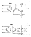
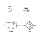
- There are various electronic components which are able to allow the passage of the current in the conditions mentioned herein, among which components we mention the thyristors in inverted and parallel connection, the triacs and the transistors combined with rectifiers. These electronic devices are intercalated in each branch of the polyphase supply system according to various circuits as may be thos shown in Figures 4 and 5 for three-phase systems, where E indicates these devices and S indicates the control instructions for the activation of said devices, which instructions will come from a programming circuit; it is possible to use any other circuit which will allow the successive circulation of cycles as described in the present description. ,
- Figures 6, 7, 8 and 9 represent the symbols of the devices E shown in Figures 4 and 5:, which symbols indicate the tyristors, the triac and the combination of rectifiers and transistors, respectively.
- The use of thyristors or controlled rectifiers connected in parallel and with inverted polarity allows, by acting on tha gates of both components, to select the necessary cycle of conduction and the angle of conduction for obtaining the division of the charges in the polyphase system and the angle of conduction corresponding to the efficient value of the alternating voltage applied in the electro-chemical process.
- The use of triacs allcws the same operating operations as the thyristors, but the instruction of control of the cycle and the angle of conduction is supplied to a single gate, this being is the characteristic of this component.
- The use of transistors allows, besides the possibilities mentioned for the thyristors and the triacs, to control an angle of conduction with completely determined beginning and end as shown in Fig. 10, but obviously with trigger circuits different from those for the thyristors and the triacs; in this way an optimization of the efficiency is obtained when using the wave zone of maximum energy.
- The thyristors in parallel and inverted connection, the triac and the assembly of transistors and rectifiers operate by means of suitable instructions from control trigger circuits, as rectifier assemblies with control of the angle of conduction; in this way, onto the electrolytic vessel there is applied a pulsating direct voltage of variable efficient value, which is utilized to achieve an electrolytic decolorization in case an excess of colouring has been produced in the preceding process.
- The rectifier wave in the cases of control by thyristors in antiparallel or triacs is shown in Fig. 11 on a diagram, as those shown in the preceding Figures, of a six-phase system. Fig. 12 represents the waveform when using transistors; in this case the transistor T2 shown in Fig. 8 would cease conducting,as well as the transistors TR1 and TR2 shown in Fig. 9, for attaining this purpose.
- The processing of the trigger instructions S .shown in Figures 4 and 5 for controlling the commutation.-of the phase circulation,the angles of circulation and the operation of the source as a rectifier; is obtainable by known multiple 'electronic means. The use of microprocessors allows, by means of some programs to be utilized in each electrochemical proces, to make the source operate in any of the ways indicated, in a completely automatic manner and with a with a control of the commutation of the phases and very precise angles of conduction. The programms-necessary in each process are registered in the memory of the microprocessor which allows a very large variety of the same.
- The electronic device described hereinabove in relation to the electrolytic - colouring of pieces of aluminium or aluminium alloys, as will be appreciated, may be applied in other industrial fields in which an unbalancing of phases is produced, as for example in the distribution of current for electric illumination, systems of electric supply for railway, etc.
- Examples of practical embodiments of the present invention will now be described in detail by way of illustration only and in no way limiting the scope of the invention.
- An aluminium section is submitted to preliminary anodization by means of a bath of sulphuric acid having a concentration of 180 g/l, at a temperature of 20°C, under a current density of -1,5 Amp/dm 2 and for a period of time of 35 minutes.
- The resulting anodized piece is submitted to the phases of the porcesso of the present invention, in the following way:
- The anodized piece is treated in a bath composed of sulphuric acid (2 g/1) and citric acid (13 g/1), by applying an alternating current with a peak voltage of 62 volt for 3 minutes, with a current density of 0,25 Amp/dm2.
- The piece resulting from the preceding operation is submitte to electrolitic colouring in a bath composed of:


- The preliminary anodization of Example 1 is repeated and thereafter the anodized piece is submitted to the phases of pre-colouring and colouring according to the present invention, under the following conditions:
- In this Example, the pre-colouring bath is composed of sulphuric acid having a concentration of 4 g/l. The alternating current is applied with a peak voltage of 65 volts, at a current density of 0,28 Amp/dm2, for two minutes. 2.- Colouring phase:
- The colouring bath is composed of CuSO4 with a concentration of 20 g/l of H2SO4 in a quantity sufficient for maintaining in the bath a pH of 1,1. Alternating current is applied at a peak voltage of 70 volts at a current density of 0,32 Amp/dm2, to obtain the following colours in the indicated periods of time:

- The preliminary anodization of Example 1 is repeated and thereafter the anodized piece is submitted to the phases of pre-colouring and colouring according to the present invention:
- The piece is treated in a bath composed of sulphuric acid (3 g/1) and citric acid (20 g/l), by applying an alternating current at a peak voltage of 70 volts, at a current density of 0,27 Amp/dm2, for 2,5 minutes.
- In this phase the treatment bath is composed of:

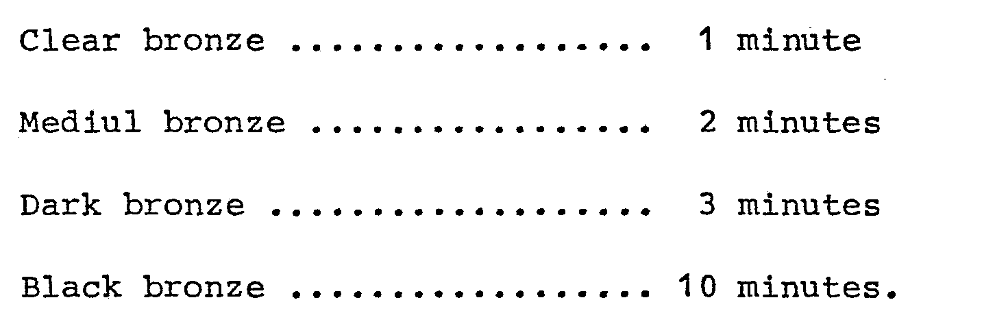
- Alternating current is applied at peak voltage of 70 volts at a current density of 0,34 Amp/dm2 , to obtain the following colours in the indicated periods of time:
- After having described to a sufficient extent the nature of the inventiin, as well as the way of carrying it out practically, it has to be pointed out that the dispositions described hereinaboveare susceptible of modifications of their details, without altering the basic -principle of the invention.
Claims (3)
Priority Applications (1)
| Application Number | Priority Date | Filing Date | Title |
|---|---|---|---|
| AT81110658T ATE15701T1 (en) | 1981-01-16 | 1981-12-21 | PROCESS FOR THE ELECTROLYTIC COLORING OF A WORKPIECE MADE OF ALUMINUM OR AN ALUMINUM ALLOY. |
Applications Claiming Priority (2)
| Application Number | Priority Date | Filing Date | Title |
|---|---|---|---|
| ES498578A ES498578A0 (en) | 1981-01-16 | 1981-01-16 | ELECTROLYTIC COLORING PROCEDURE OF AN ALUMINUM PART OR ALUMINUM ALLOY |
| ES498578 | 1981-01-16 |
Publications (2)
| Publication Number | Publication Date |
|---|---|
| EP0056478A1 true EP0056478A1 (en) | 1982-07-28 |
| EP0056478B1 EP0056478B1 (en) | 1985-09-18 |
Family
ID=8481708
Family Applications (1)
| Application Number | Title | Priority Date | Filing Date |
|---|---|---|---|
| EP81110658A Expired EP0056478B1 (en) | 1981-01-16 | 1981-12-21 | Process for electrolytically colouring a piece of aluminium or aluminium alloy |
Country Status (10)
| Country | Link |
|---|---|
| US (1) | US4421610A (en) |
| EP (1) | EP0056478B1 (en) |
| JP (1) | JPS5834197A (en) |
| AT (1) | ATE15701T1 (en) |
| BR (1) | BR8200132A (en) |
| CA (1) | CA1212351A (en) |
| DE (1) | DE3172388D1 (en) |
| ES (1) | ES498578A0 (en) |
| MX (1) | MX156527A (en) |
| PT (1) | PT74278B (en) |
Cited By (1)
| Publication number | Priority date | Publication date | Assignee | Title |
|---|---|---|---|---|
| GB2237817A (en) * | 1989-11-08 | 1991-05-15 | Sandoz Ltd | Electrolytic colouring of anodized aluminium |
Families Citing this family (9)
| Publication number | Priority date | Publication date | Assignee | Title |
|---|---|---|---|---|
| JPS61113793A (en) * | 1984-11-07 | 1986-05-31 | Okinawa Pref Gov | Electrolytic coloring method of aluminum material |
| DE3530934C1 (en) * | 1985-08-29 | 1987-04-16 | Chemal Gmbh & Co Kg | Process for the uniform electrolytic coloring of anodized aluminum or aluminum alloys |
| US4704559A (en) * | 1986-02-25 | 1987-11-03 | Seiko Instruments & Electronics Ltd. | Matrix type multi-color display device |
| DE3718741A1 (en) * | 1986-07-23 | 1988-02-04 | Henkel Kgaa | METHOD AND CIRCUIT FOR THE ELECTROLYTIC COLORING OF ANODIZED ALUMINUM SURFACES |
| DE3743113A1 (en) * | 1987-12-18 | 1989-06-29 | Gartner & Co J | METHOD FOR ELECTROLYTICALLY CARBONIZING ANODICALLY PRODUCED OXIDIVE LAYERS ON ALUMINUM AND ALUMINUM ALLOYS |
| US4931151A (en) * | 1989-04-11 | 1990-06-05 | Novamax Technologies Holdings Inc. | Method for two step electrolytic coloring of anodized aluminum |
| US5674371A (en) * | 1989-11-08 | 1997-10-07 | Clariant Finance (Bvi) Limited | Process for electrolytically treating aluminum and compositions therefor |
| ES2052455B1 (en) * | 1992-12-31 | 1994-12-01 | Novamax Tech Holdings | PROCEDURE FOR ELECTROLYTICALLY OBTAINING ON ANODIZED ALUMINUM OF A COLOR RANGE OF VISIBLE SPECTRUM. |
| CN105177666B (en) * | 2015-09-23 | 2017-09-15 | 浙江鑫祥新能源科技股份有限公司 | A kind of Aluminum Coloring technique |
Citations (5)
| Publication number | Priority date | Publication date | Assignee | Title |
|---|---|---|---|---|
| GB1267235A (en) * | 1969-05-06 | 1972-03-15 | ||
| GB1301577A (en) * | 1969-05-09 | 1972-12-29 | ||
| GB1440733A (en) * | 1973-08-24 | 1976-06-23 | Sumitomo Chemical Co | Electrolytic colouration of anodic oxide film on aluminium |
| US4011152A (en) * | 1975-03-12 | 1977-03-08 | Empresa Nacional Del Aluminio, S.A. | System for autocontrolling and regulating the average value of the voltage applied to processes for the electrolytic coloring of anodized aluminum |
| GB1489482A (en) * | 1974-05-22 | 1977-10-19 | Riken Light Metal Ind Co | Method of forming coloured oxide film on aluminium or its alloy by anodizing |
Family Cites Families (9)
| Publication number | Priority date | Publication date | Assignee | Title |
|---|---|---|---|---|
| US3634208A (en) * | 1968-09-26 | 1972-01-11 | Aiden Kk | Coloring method of aluminum anodic oxide coating film |
| JPS547267B2 (en) * | 1973-09-21 | 1979-04-05 | ||
| CH601502A5 (en) * | 1974-07-31 | 1978-07-14 | Alusuisse | |
| JPS5129328A (en) * | 1974-08-29 | 1976-03-12 | Sumitomo Chemical Co | Aruminiumu mataha aruminiumugokin no hyomenniseiseisaseta yokyokusankahimaku no denkaichakushokuhoho |
| JPS5423664B2 (en) * | 1975-03-06 | 1979-08-15 | ||
| JPS52148442A (en) * | 1976-02-18 | 1977-12-09 | Riken Keikinzoku Kogyo Kk | Colored oxide coating for aluminum material and method of forming the same |
| US4022671A (en) * | 1976-04-20 | 1977-05-10 | Alcan Research And Development Limited | Electrolytic coloring of anodized aluminum |
| JPS548131A (en) * | 1977-06-22 | 1979-01-22 | Mitsui Keikinzoku Kako | Method of electrolytically coloring aluminum and aluminum alloys |
| JPS5471735A (en) * | 1977-11-21 | 1979-06-08 | Nitsutetsu Kaatenooru Kk | Surface treating of aluminium and aluminium alloy |
-
1981
- 1981-01-16 ES ES498578A patent/ES498578A0/en active Granted
- 1981-04-16 US US06/254,589 patent/US4421610A/en not_active Expired - Fee Related
- 1981-12-21 AT AT81110658T patent/ATE15701T1/en not_active IP Right Cessation
- 1981-12-21 DE DE8181110658T patent/DE3172388D1/en not_active Expired
- 1981-12-21 EP EP81110658A patent/EP0056478B1/en not_active Expired
-
1982
- 1982-01-04 MX MX190735A patent/MX156527A/en unknown
- 1982-01-12 BR BR8200132A patent/BR8200132A/en unknown
- 1982-01-13 PT PT74278A patent/PT74278B/en unknown
- 1982-01-14 JP JP57004777A patent/JPS5834197A/en active Granted
- 1982-01-18 CA CA000394317A patent/CA1212351A/en not_active Expired
Patent Citations (6)
| Publication number | Priority date | Publication date | Assignee | Title |
|---|---|---|---|---|
| GB1267235A (en) * | 1969-05-06 | 1972-03-15 | ||
| GB1301577A (en) * | 1969-05-09 | 1972-12-29 | ||
| GB1440733A (en) * | 1973-08-24 | 1976-06-23 | Sumitomo Chemical Co | Electrolytic colouration of anodic oxide film on aluminium |
| GB1489482A (en) * | 1974-05-22 | 1977-10-19 | Riken Light Metal Ind Co | Method of forming coloured oxide film on aluminium or its alloy by anodizing |
| US4011152A (en) * | 1975-03-12 | 1977-03-08 | Empresa Nacional Del Aluminio, S.A. | System for autocontrolling and regulating the average value of the voltage applied to processes for the electrolytic coloring of anodized aluminum |
| GB1552609A (en) * | 1975-05-12 | 1979-09-19 | Empresa Nacional Aluminio | Voltage regulation for electrolytic colouring |
Cited By (4)
| Publication number | Priority date | Publication date | Assignee | Title |
|---|---|---|---|---|
| GB2237817A (en) * | 1989-11-08 | 1991-05-15 | Sandoz Ltd | Electrolytic colouring of anodized aluminium |
| DE4034854A1 (en) * | 1989-11-08 | 1991-05-16 | Sandoz Ag | METHOD FOR ELECTROLYTICALLY CRYING ALUMINUM AND ALUMINUM ALLOYS |
| GB2237817B (en) * | 1989-11-08 | 1994-03-02 | Sandoz Ltd | Process for electrolytically treating aluminium and aluminium alloys |
| DE4034854C2 (en) * | 1989-11-08 | 2000-08-17 | Clariant Finance Bvi Ltd | Process for the electrolytic dyeing of aluminum and aluminum alloys |
Also Published As
| Publication number | Publication date |
|---|---|
| ATE15701T1 (en) | 1985-10-15 |
| MX156527A (en) | 1988-09-07 |
| PT74278A (en) | 1982-02-01 |
| JPH028038B2 (en) | 1990-02-22 |
| BR8200132A (en) | 1982-11-03 |
| CA1212351A (en) | 1986-10-07 |
| ES8201232A1 (en) | 1981-12-01 |
| PT74278B (en) | 1983-06-27 |
| US4421610A (en) | 1983-12-20 |
| DE3172388D1 (en) | 1985-10-24 |
| ES498578A0 (en) | 1981-12-01 |
| EP0056478B1 (en) | 1985-09-18 |
| JPS5834197A (en) | 1983-02-28 |
Similar Documents
| Publication | Publication Date | Title |
|---|---|---|
| EP0056478B1 (en) | Process for electrolytically colouring a piece of aluminium or aluminium alloy | |
| US3669856A (en) | Process for the production of colored protective coatings on articles of aluminum or aluminum alloys | |
| US3704209A (en) | Method for electrochemical coloring of aluminum and alloys | |
| JP3145117B2 (en) | An improved method of current generation and control system for electrolytic treatment | |
| US4226680A (en) | Process for electrolytic coloration of anodized aluminium | |
| US4798656A (en) | Process for electrolytically dyeing an anodic oxide layer on aluminum or aluminum alloys | |
| RU2181392C1 (en) | Apparatus for micro arc oxidation of metals and alloys thereof | |
| US3788956A (en) | Electrolytic coloring of anodized aluminum | |
| RU2083731C1 (en) | Device for microarc oxidation of metals and alloys | |
| RU2857142C1 (en) | Device for micro-arc and thermo-electrochemical oxidation of products made of valve metals and their alloys | |
| RU2027292C1 (en) | Converter of the alternating voltage into the asymmetric alternating one | |
| JPH0121876B2 (en) | ||
| JPS6345398A (en) | Method for electrolytically coloring aluminum or aluminum alloy | |
| US2651610A (en) | Method of electroplating zinc | |
| SU993417A1 (en) | Contact-free converter for power supply of electroplating bathes with periodic current with back pulse | |
| KR101633222B1 (en) | Power supply apparatus for aluminium anodic oxidation | |
| SU1174498A1 (en) | Device for supplying periodic current with back pulse to electroplating tanks | |
| SU1135821A1 (en) | Arrangement for power supply of electroplating baths | |
| JPS58153797A (en) | Coloration of light metal | |
| JPS621252Y2 (en) | ||
| JPH1096099A (en) | Electrodeposition coating method for aluminum surface treatment | |
| JPH0343235Y2 (en) | ||
| NO119560B (en) | ||
| Rodriguez | Electrolytic Coloring Process | |
| HK1007578B (en) | Improvements to current generation and control systems for electrolytic processes |
Legal Events
| Date | Code | Title | Description |
|---|---|---|---|
| PUAI | Public reference made under article 153(3) epc to a published international application that has entered the european phase |
Free format text: ORIGINAL CODE: 0009012 |
|
| AK | Designated contracting states |
Designated state(s): AT BE CH DE FR GB IT LU NL SE |
|
| 17P | Request for examination filed |
Effective date: 19830117 |
|
| ITF | It: translation for a ep patent filed | ||
| GRAA | (expected) grant |
Free format text: ORIGINAL CODE: 0009210 |
|
| AK | Designated contracting states |
Designated state(s): AT BE CH DE FR GB IT LI LU NL SE |
|
| PG25 | Lapsed in a contracting state [announced via postgrant information from national office to epo] |
Ref country code: AT Effective date: 19850918 |
|
| REF | Corresponds to: |
Ref document number: 15701 Country of ref document: AT Date of ref document: 19851015 Kind code of ref document: T |
|
| PG25 | Lapsed in a contracting state [announced via postgrant information from national office to epo] |
Ref country code: SE Effective date: 19850930 |
|
| REF | Corresponds to: |
Ref document number: 3172388 Country of ref document: DE Date of ref document: 19851024 |
|
| ET | Fr: translation filed | ||
| PG25 | Lapsed in a contracting state [announced via postgrant information from national office to epo] |
Ref country code: LU Free format text: LAPSE BECAUSE OF NON-PAYMENT OF DUE FEES Effective date: 19851231 |
|
| PLBE | No opposition filed within time limit |
Free format text: ORIGINAL CODE: 0009261 |
|
| STAA | Information on the status of an ep patent application or granted ep patent |
Free format text: STATUS: NO OPPOSITION FILED WITHIN TIME LIMIT |
|
| 26N | No opposition filed | ||
| PGFP | Annual fee paid to national office [announced via postgrant information from national office to epo] |
Ref country code: BE Payment date: 19891009 Year of fee payment: 9 |
|
| PGFP | Annual fee paid to national office [announced via postgrant information from national office to epo] |
Ref country code: FR Payment date: 19891020 Year of fee payment: 9 |
|
| PGFP | Annual fee paid to national office [announced via postgrant information from national office to epo] |
Ref country code: CH Payment date: 19891024 Year of fee payment: 9 |
|
| PGFP | Annual fee paid to national office [announced via postgrant information from national office to epo] |
Ref country code: DE Payment date: 19891228 Year of fee payment: 9 |
|
| ITTA | It: last paid annual fee | ||
| PGFP | Annual fee paid to national office [announced via postgrant information from national office to epo] |
Ref country code: NL Payment date: 19891231 Year of fee payment: 9 Ref country code: GB Payment date: 19891231 Year of fee payment: 9 |
|
| PG25 | Lapsed in a contracting state [announced via postgrant information from national office to epo] |
Ref country code: GB Effective date: 19901221 |
|
| PG25 | Lapsed in a contracting state [announced via postgrant information from national office to epo] |
Ref country code: LI Effective date: 19901231 Ref country code: CH Effective date: 19901231 Ref country code: BE Effective date: 19901231 |
|
| BERE | Be: lapsed |
Owner name: RONAIN S.A. Effective date: 19901231 |
|
| PG25 | Lapsed in a contracting state [announced via postgrant information from national office to epo] |
Ref country code: NL Effective date: 19910701 |
|
| NLV4 | Nl: lapsed or anulled due to non-payment of the annual fee | ||
| GBPC | Gb: european patent ceased through non-payment of renewal fee | ||
| PG25 | Lapsed in a contracting state [announced via postgrant information from national office to epo] |
Ref country code: FR Effective date: 19910830 |
|
| REG | Reference to a national code |
Ref country code: CH Ref legal event code: PL |
|
| PG25 | Lapsed in a contracting state [announced via postgrant information from national office to epo] |
Ref country code: DE Effective date: 19910903 |
|
| REG | Reference to a national code |
Ref country code: FR Ref legal event code: ST |