EP0056525A1 - Division system - Google Patents
Division system Download PDFInfo
- Publication number
- EP0056525A1 EP0056525A1 EP81306019A EP81306019A EP0056525A1 EP 0056525 A1 EP0056525 A1 EP 0056525A1 EP 81306019 A EP81306019 A EP 81306019A EP 81306019 A EP81306019 A EP 81306019A EP 0056525 A1 EP0056525 A1 EP 0056525A1
- Authority
- EP
- European Patent Office
- Prior art keywords
- decimal
- digit
- signal
- divisor
- subtraction
- Prior art date
- Legal status (The legal status is an assumption and is not a legal conclusion. Google has not performed a legal analysis and makes no representation as to the accuracy of the status listed.)
- Granted
Links
Images




Classifications
-
- G—PHYSICS
- G06—COMPUTING OR CALCULATING; COUNTING
- G06F—ELECTRIC DIGITAL DATA PROCESSING
- G06F7/00—Methods or arrangements for processing data by operating upon the order or content of the data handled
- G06F7/38—Methods or arrangements for performing computations using exclusively denominational number representation, e.g. using binary, ternary, decimal representation
- G06F7/48—Methods or arrangements for performing computations using exclusively denominational number representation, e.g. using binary, ternary, decimal representation using non-contact-making devices, e.g. tube, solid state device; using unspecified devices
- G06F7/491—Computations with decimal numbers radix 12 or 20.
- G06F7/4915—Multiplying; Dividing
- G06F7/4917—Dividing
Definitions
- This invention relates generally to the execution of decimal arithmetic instructions by a commercial instruction processor of a data processing system, and more specifcally to apparatus which, during the execution of a decimal divide instruction by the successive subtraction method, tests the high order positions of the divisor and the remainder to anticipate a negative result of the next subtration.
- Data processing systems commonly perform the decimal divide instruction by successive subtractions of the dividend by the divisor.
- the subtractions are carried out by aligning the most significant decimal digit positions of the dividend and divisor and subtracting a decimal digit at a time, least significant decimal digit position first.
- the high order quotient decimal digit is generated by counting the number of subtractions of the dividend by the divisor that gives a positive remainder. A negative subtraction result indicates that no further subtractions are needed, the divisor is added back to the remainder, and the unsuccessful subtraction is not counted.
- the divisor is shifted over one digit position to the right and successive subtractions are made of the remainder to generate the .next lower order quotient decimal digit.
- the present invention provides apparatus for performing non-binary division including subtracting means for repeatedly subtracting the contents of a divisor register from the contents of a dividend/partial remainder register, with counter means generating successive quotient digits by counting the number of subtractions resulting in a positive partial remainder, characterized by means for storing the most significant decimal digit of each of the sequence of partial remainders and generating a ZERO signal when its contents are a decimal ZERO, from which a decode signal is generated, the subtracting means including multiplexer means responsive to the decode signal for generating a test signal for determining if the most significant decimal digit of each of the sequence of partial remainders is less than the most significant decimal digit of the divisor for avoiding a subtraction and an add back sequence.
- a commercial instruction processor executes a decimal divide instruction by storing the divisor in an OP1 register and the dividend in an OP2 register.
- the content of an OPlA register points to the position of the least significant divisor decimal digit in OP1.
- the content of an OP2k register points to the decimal digit position in OP2 that aligns the most significant decimal digits of OP1 and OP2.
- An arithmetic logic unit ALUl subtracts each decimal digit in OP1 from the respective decimal digit in OP2 to generate a partial remainder decimal digit which replaces the OP2 decimal digit.
- a test request signal is applied to a multiplexer.
- the multiplexer output signal is applied to ALU1 which subtracts the divisor most significant decimal digit from the most significant partial remainder decimal digit in OP2. If the result of the test subtraction is a positive decimal digit, then the divisor in OP1 is subtracted from the partial remainder in OP2.
- the result of the test subtraction is a negative number indicating that another complete subtraction cycle of the divisor in OP1 from the partial remainder in OP2 would result in a negative remainder and an add back into OP2, then the following steps are taken.
- the most significant partial remainder decimal digit is transferred from OP2 to an MIER register.
- the initial contents of OP2 A are incremented by hexadecimal ONE to essentially shift the divisor in OPI one decimal digit position to the right.
- the quotient digit stored in an ALQR register is stored in a scratchpad memory. The quotient digit stores the number of subtractions of the divisor from the dividend that resulted in a positive partial remainder.
- the test request signal is applied to the multiplexer.
- the multiplexer output conditions the ALU to subtract the most significant divisor decimal digit from the new partial remainder most significant digit. A negative answer indicates that this subtraction sequence is completed, the quotient is stored in scratchpad memory, the new partial remainder decimal digit is transferred from OP2 to MIER, and OP2A is incremented.
- FIG. 1 is an overall block diagram of a data processing system which includes a main memory 4, a plurality of input/output controllers 6 and a cache/memory management unit (C/MMU) 12; all coupled in common to a system bus 14. Coupled to the C/MMU 12 are a central processor unit (CPU) 2, a commercial instruction processor (CIP) 10 and a scientific instruction processor (SIP) 8 via buses 20, 18 and 22 respectively.
- the C/MMU 12, CIP 10, CPU 2 and SIP 8 are coupled in common to a common bus 16. Also, CPU 2 is coupled to the CIP 10 and the SIP 8 via buses 24 and 26 respectively.
- the CIP 10 executes a set of instructions designed to facilitate processing of character strings and decimal data.
- the SIP 8 executes a set of scientific instructions particularly useful for FORTRAN applications. This set includes arithmetic operations on single and double precision floating point operands and single and double word integer operands.
- CPU 2 determines from the operation code of the instructions if the instruction is to be processed by the CPU 2, the CIP 10, or the SIP 8.
- the CPU 2 receives status information from the CIP 10 or SIP 8 over buses 24 and 26 respectively. If the CIP 10 or SIP 3 is available, the CPU 2 sends the necessary information out on common bus 16 and also bus 26 for the SIP 8.
- the CIP 10 or the SIP 8 processes the instruction and is operative with the C/MMU 12 via bus 18 or 22 respectively and bus 16 for processing the instruction.
- the CIP 10 processes instructions which include the following:
- Main memory 4 stores instructions and data and is operative with the C/MMU 12 for the transferring of instructions and data over system bus 14 under control of CPU 2 via bus 20.
- the C/MMU 12 which includes a cache memory stores the instructions and data currently being processed by the CPU 2, CIP 10 and SIP 8.
- the CPU 2 is also operative for initiating transfers of data between the I/O controllers 6 and main memory 4.
- function code register 96 selects a firmware word in a control store 60 via control store addressing logic 58.
- the firmware word is loaded into a control store data register 62 and conditions CIP 10 to receive additional control information from CPU 2.
- a control store decode logic 61 generates control signals by decoding the output signals RD 00-67+ from control store data register 62. Signals RD 52-67+ applied to control store addressing logic 58 results in control store 60 branching to a specified address location.
- the CIP 10 instructions operate on three data types, decimal strings containing binary coded decimal digits, alphanumeric strings containing ASCII characters and binary numbers having 16 or 32 bit precision.
- Decimal data operands are referenced by the location of the most significant digit and length and may have one or two digits in a byte. Packed decimal operands store two digits per byte and string decimal operands store one digit per byte.
- String decimal operands may be unsigned and assumed positive, may have a leading sign byte placed before the most significant decimal byte, a trailing sign byte placed after the least significant decimal byte or a trailing overpunched sign included with the least significant decimal byte.
- Packed decimal operands may be unsigned implying a positive sign or have a trailing sign.
- Binary data operands have the most significant binary bit as a sign bit with the binary point assumed to the right of the least significant binary bit using 2's complement notation.
- the double words received by CIP 10 from CPU 2 following the instruction word specifying a decimal arithmetic operation indicates the decimal type, string or packed, sign information, the length of the operand and tne effective address. This is the address of the byte containing the most significant character (4 or 8 bits/character).
- control store 60 Initially during the processing of a decimal numeric instruction, control store 60 generates signals via control store data register 62 causing the address control unit 82 to send the main memory 4 address of the operand 1 word containing the sign character to C/MMU 12.-
- the operand 1 word containing the sign character is received by common bus data interface 80 and stored in OP1 64 and OP2 66.
- the sign character is selected by selector 70 for transfer to a sign decode overpunch encode logic 74 where it is decoded into status bits indicating an illegal sign or a negative sign.
- the control store addressing logic 58 is responsive to the illegal sign status bit and the negative sign status bit. If the sign is legal, then the negative sign status bit is stored in the microprogram status register 94.
- the operand 2 word containing the sign is processed in a similar manner and stored in OP2 66.
- Selector 70 transfers the sign character to sign decode overpunch encode logic 74 where it is decoded into the illegal sign or the negative sign and stored in the microprogram status register 94. This allows the CIP 10 to abort the instruction and notify the CPU 2 if an illegal sign was detected.
- a decimal add instruction is indicated by an output task function code, 07 16 and the instruction register 96 storing hexadecimal 20 16 .
- operand 1 is added to operand 2 and the result of the addition is stored in the location in main memory 4 that stored operand 2.
- the CIP 10 waits for the CPU 2 to send the additional control information required for the CIP 10 to execute the decimal add instruction.
- Th.e additional control information consists of up to 3 double words describing operand 1 and up to 3 double words describing operand 2.
- the last double word received from the CPU 2 is an output last data descriptor indicated by a function code of 1F 16 .
- the first of the 3 double words for each operand contains the effective virtual byte address of the operand which indicates the start of the operand in main memory 4, that is, the leftmost or lowest addressed byte containing some of the operand.
- the second double word may contain an indirect length.
- the third double word contains the data descriptor which specifies the data type and the position within the initial word received from main memory 4 of the start of the operand.
- the six double words are stored in the address control unit 82.
- the output of instruction register 56 addresses a word in control store 60 to start the CIP 10 execution of the decimal add instruction by sending the main memory 4 address for the low order word of operand 1 containing the least significant decimal digits to the C/ MMU 12 via bus 18.
- the first word of operand 1 is read from main memory 4 or from a cache memory (not shown) in C/MMU 12 and transferred to CIP 10 via common bus 16 and stored in OP1 64.
- the low order word of operand 2 is received by CIP 10 and stored in data scratchpad unit 50 and in OP2 66.
- each data descriptor word describing the characteristics of the two operands (ASCII string or packed) and the computed position of the least significant decimal digit in tneir respective low order words for operands 1 and 2 are stored in OPlA 84 and OP2A 78 respectively.
- the length of operands 1 and 2 is stored in descriptor operand length processing logic 88.
- the O P I A 84 output is applied to a selector 68 and the OP2A 78 output is applied to a selector 70 for selecting the operand 1 and operand 2 decimal digits as they are transferred from OP1 64 and OP2 66 for processing by a decimal/binary ALU 76, one decimal digit at a time.
- the resulting decimal digit of the addition is transferred from ALU 76 to OP2 66 via an internal bus (BI) 100, replacing the operand 2 decimal digit that contributed to this result.
- OP1A 84 keeps track of the number of decimal digits remaining in OP1 64 from the transfer of the low order word.
- OPlA 84 signals the branching logic in control store addressing logic 58 to address a word in control store 60 which fetches the next word of operand 1 from main memory 4 via C/MMU 12.
- the address of the next word of operand 1 is sent from address control unit 82 to C/MMU 12 via bus 18.
- OP2A 78 signals the branching logic in control store addressing logic 58 to enter into a firmware routine to transfer the resulting word of the addition stored in OP2 66 to common bus data interface 80 for transfer to main memory 4 via common bus 16 to C/MMU 12 at the location specified by the address from address control unit 82 over bus 18.
- a copy of the result is stored in data scratchpad unit 50.
- a read cycle is initiated to read the next word of operand 2 by sending the next address from address control unit 82 to C/MMU 12 via bus 18.
- descriptor operand length processing logic 88 controls the filling out of the field of the result in accordance with the remaining decimal digits of the longer operand.
- the entire multiplicand, operand 2 is transferred from main memory 4 to the data scratchpad unit 50 via common bus data interface 80 and BI bus 100.
- a multiplier double word of operand 1 is transferred to OP1 64 via common bus data interface 80 and BI bus 100.
- the least significant multiplier digit is read into a multiply register/counter 52 from OP1 64 via BI bus 100 and is applied to the input address terminals of a multiply programmable read only memory (PROM) 54.
- PROM multiply programmable read only memory
- Each double word of the multiplicand in turn is transferred to OP1 64 from the data scratchpad 50.
- Each multiplicand digit in turn is applied to tne remaining input address terminals of PROM 54 from OP1 64 via selector 68 to generate the partial product digits.
- Each partial product digit is applied to ALU 76 via selector 68 where it is added to a corresponding decimal digit stored in OP2 66 and the resultant partial product stored back in OP2 66.
- the next multiplier digit is read into multiply register/counter 52 and the output applied to PROM 54. Again each multiplicand digit in turn is applied to PROM 54 and the partial product digits are applied to ALU 76 via selector 68 where they are added to the selected partial product digits stored in OP2 66.
- OP2A 78 controls selector 70 to select the partial product digit to be applied to ALU 76.
- the partial product result from ALU 76 is again stored in OP2 66 via BI bus 100.”
- the data scratchpad unit 50 contains the product of the multiplication. This product is written into main memory 4 via OP2 66, common bus data interface 80 and common bus 16.
- a decimal division instruction is executed by receiving the dividend and divisor in common bus data interface 80 from C/MMU 12 via common bus 16 for storage in the data scratchpad unit 50. Portions of the divisor are stored in OP1 64 in turn and portions of the dividend/partial remainder are stored in OP2 66 in turn.
- the CIP 10 executes the decimal divide instruction by a series of successive subtractions and counting the number of successful subtractions in an ALQR register/counter 72.
- a successful subtraction is one in which the result is a positive number.
- the divisor in OP1 64 is applied to ALU 76 through selector 68, a decimal digit at a time, the least significant decimal digit first.
- the dividend in OP2 66 is applied to ALU 76 through selector 70, a decimal digit at a time.
- OP2A 78 controls selector 70 to select the decimal digit from OP2 66 that would cause the most significant decimal digits of the divisor in OP1 64 to be aligned with the most significant decimal digit of the dividend for the subtraction operation.
- the output of ALU 76 is stored in OP2 66 via BI bus 100 and the contents of ALQR 72 are incremented if the result of the subtraction of the high order decimal digits with the divisor is a positive number.
- the divisor in OP1 64 is again subtracted from the result of the previous subtraction which is stored in OP2 66 and the contents of ALQR 72 again are incremented if the result of the subtraction is positive.
- the divisor stored in OP1 64 is then added to OP2 66 and the contents of ALQR 72 containing a quotient digit are transferred to the data scratchpad unit 50.
- OP2 66 and data scratchpad unit 50 now contain the result of the last successful subtraction in the high order decimal digits and the remaining decimal digits are the original low order decimal digits of the dividend.
- the divisor is subtracted from the dividend one digit position to the right of the previous set of subtractions to develop the next quotient digit.
- the subtraction operation is repeated as described above with ALQR 72 being incremented for each positive result of the subtraction.
- the first quotient digit stored in data scratchpad unit 50 is transferred to OP2 66 via BI bus 100.
- the contents of ALQR 72 containing the second quotient digit is transferred to OP2 66 via selector 68, ALU 76 and internal bus 100 where it is appended to the first quotient digit for storage in the data scratchpad unit 50.
- the partial dividend is transferred back to OP2 66 from the data scratcnpad unit 50.
- the shifting of the divisor and subsequent subtraction operations are repeated until after computing a quotient digit with the least significant decimal digit of the divisor aligned with the least significant decimal digit of the dividend.
- the last quotient decimal digit from ALQR 72 is merged with the rest of the quotient in the data scratchpad unit 50 and the portion of the remainder now stored in OP2 66 is stored into the data scratchpad unit 50 via BI bus 100.
- the quotient and remainder in data scratchpad unit 50 are then stored in main memory 4.
- a CIP indicator register 90 is set by the control signals to indicate the status of CIP 10.
- Register 90 includes an overflow indicator which is set during decimal operations when the receiving field cannot store all significant digits of the result or a divide by zero is detected.
- a truncation indicator is set during alphanumeric operations when the receiving field cannot contain all characters of the result.
- a sign fault indicator is set during decimal operations when a negative result is stored in an unsigned field.
- a greater-than indicator is set during the execution of certain decimal and alphanumeric instructions when the result is greater than zero for decimal numeric operations or operand 1 is greater than operand 2 for decimal or arithmetic comparisons.
- a less-than indicator is set during the execution of certain decimal and alphanumeric instructions when the result is less than zero for decimal arithmetic instructions or operand 1 is less than operand 2 for either decimal or alphanumeric comparisons.
- a CIP mode register 92 stores an overflow trap mask and a truncation trap mask which are indications of which special action the CIP 10 and CPU 2 should take when the overflow or truncation condition arises.
- a system clock logic 86 includes a 160 nanosecond four phase clock that provides clock signals to trigger all CIP 10 registers and all test and control flops, stabilize registers after loading, signify that address, data, control and parity are valid allowing initiation of a local bus cycle. In addition, the system clock logic 86 may be stalled when additional time is required to complete certain CIP 10 functions.
- the system clock logic 86 generates a BUSY signal over common bus 16 to indicate to CPU 2 that the CIP 10 is not available, receives a DCN signal from the C/MMU 12 bus to signal the CIP 10 that data for the CIP 10 is on the common bus 8, generates a REQUEST for use of the common bus 16, and waits for a GRANT from the C/MMU 12.
- the microprocessor status register 94 in addition to storing operand sign information also stores an indication if an overflow was detected in executing a decimal numeric instruction, whether an encode or a decode overpunched sign operation is required, and when a decimal add operation is completed.
- the data scratchpad unit 50 includes a register file D (RFD) 50-1, a register/counter (AA) 50-2, a register/counter (AB) 50-3 and a MUX 50-4.
- RFD 50-1 includes 8 4-bit random access memories organized to store 16 32-bit double words.
- RFD 50-1 is addressed from either AA 50-2 via signals RFDAA 0-3+, MUX 50-4 and signals RFDAD 0-3+, or from AB 50-3 via signals RFDAB 0-3+, MUX 50-4 and signals RFDAD 0-3+.
- RFD 50-1 is coupled to BI bus 100 via signals BIDT 00-31-.
- AA 50-2 and AB 50-3 are loaded from BI bus 100 via signals BIDT 8-11+.
- AA 50-2 stores the location in RFD 50-1 of the multiplicand words
- AB 50-3 stores the location of the partial product words.
- the descriptor operand length processing logic 88 includes a counter 1 88-1, a counter 2 88-2 and a counter 3 88-3 coupled to a MUX 88-4 via signals CTR1 0-3+, CTR2 0-3+ and CTR3 0-3+ respectively; and coupled to a MUX 88-5 via signals CTR1 4-7+, CTR2 4-7+ and CTR3 4-7+ respectively.
- Signals RD 16-19+ are applied to MUX 88-4 and signals RD 20-23+ are applied to MUX 88-5 to provide miscellaneous constants for transfer onto BI bus 100.
- Output signals CTKT 0-3+ of MUX 88-4 are coupled to their respective signals CTBI 0-3+.
- Output signals CTKT 4-7+ of MUX 88-5 are coupled to their respective signals CTBI 4-7+.
- Signals CTBI 0-3+ are coupled through MUX 76-11 to BI bus 100 signals BIDT 0-3+, BIDT 8-11+, BIDT 16-19+ and BIDT 24-27+ respectively.
- Signals CTBI 4-7+ are coupled through MUX 76-11 to BI bus 100 signals BIDT 4-7+, BIDT 12-15+, BIDT 20-23+ and BIDT 28-31+ respectively.
- Counter 1 88-1, counter 2 88-2 and counter 3 88-3 are loaded from BI bus 100 via signals BIDT 16-23+.
- counter 1 88-1 stores the number of decimal digits in operand 1
- counter 2 88-2 stores the number of decimal digits in operand 2.
- counter 1 88-1 and counter 2 88-2 store the number of multiplicand decimal digits remaining to be applied to multiply PROM 54 for the multiplier digit stored in multiply register (MIER) 52.
- Counter 3 88-3 may store the number of decimal digits of the multiplier remaining for processing or the effective length of the multiplicand.
- the decimal binary ALU 76 includes a 4-bit arithmetic logic unit (ALU1) 76-2 for processing decimal numeric arithmetic operations and a 4-bit arithmetic logic unit (ALU2) 76-3 for processing alphanumeric operations and code conversions such as binary to decimal and decimal to binary.
- ALU1 output signals ALUDG 0-3+ are applied to a MUX 76-8, a MUX 76-9 and a decimal correction unit 76-7.
- Output signals ALXS 60,61+ and ALUDG2- from decimal correction 76-7 are applied to MUX's 76-8 and 76-9.
- MUX 76-8 output signals CTBI 0-3+ and MUX 76-9 output signals CTSI 4-7+ are applied to MUX 76-11 as previously described.
- the output signals RFDAD 0-3+ of MUX 50-4 are applied to MUX 76-11.
- Output signals OP1X 00-31+ from RFD 50-1 and OP1 64 are applied to MUX 76-11 as are the output signals OP2D 00-31+ from OP2 66.
- the outputs of OP1A 84 and OP2A 78, signals OP1AD 0-2+, OP1TYP+, OP2AD 0-2+ and OP2TYP+, are applied to MUX 76-11 and appear at the MUX 76-11 output as signals BIDT 12-15+. Also applied to MUX 76-11 are signals ALQR+ from ALQR 72 and MIER+ from MIER 52 and appear at the MUX 76-11 output as signal BIDT 28-31+ and BI DT 20-23+.
- a LU2 76-3 signals ALUZN 0-3+
- ALUZN 0-3+ is applied to a MUX 76-10.
- a hexadecimal 3 is applied to MUX 76-10 whose output signals A LZ O N 0-3+ are applied to MUX 75-11.
- a register file C (RFC) 82-1 is coupled to the BI bus 100. Selected signals of BI bus 100, BIDT 00-31+, are stored in positions A,0-23 of RFC 82-1. The logic selecting the input bit positions is not shown since it is not pertinent to the invention. Output signals RFC A,0-23+ from RFC 82-1 are applied to MUX 76-11 and appear on BI bus 100 as signals BIDT 7-31+.
- a units carry 76-5 and a tens carry 76-6 are coupled to ALU1 76-2 via a MUX 76-4.
- the units carry 76-5 is operative when the multiply PROM 54 generates the units position decimal digit
- the tens carry 76-6 is operative when the multiply PROM 54 generates the tens position decimal digit.
- a double word of the partial product is stored in OP2 66 and a double word of the multiplicand is stored in OP1 64.
- the OP2 66 output signals OP2D 00-31+ are applied to selector 70.
- the OP2A 78 output signals OP2AD 0-2+ and OP2TYP+ enable selector 70 to transfer the selected decimal digit to terminal A of ALU1 76-2 via signals AL2DGO+.
- the OP1A 84 output signals OP1AD 0-2+ and OP1TYP+ enable selector 68 to transfer the selected multiplicand digit, received via signals OP1X 00-31+, to multiply PROM 54 via signals OP1DG 0-3+.
- a MUX 68-1 transfers the output of ALQR 72, signals ALQR 0-3+, or the output of selector 68-2, signals OP1DG 0-3+, to terminal B of ALU1 76-2 via signals OP1QD 0-3+ and AL1DG 0-3+.
- an operand 1 decimal digit in OP1 64 or RFD 50-1 and an operand 2 decimal digit in OP2 66 may be combined in ALU1 76-2 or the contents of ALQR 72 may be combined with a selected decimal digit position in OP2 66 during a divide operation.
- RFC 82-1 of the address control unit 82 stores the instruction and the data descriptors describing the characteristics of the operands.
- RFC 82-1 is made up of 6 4-bit random access memories and a portion of a seventh random access memory organized as 16 25-bit words. Certain locations of RFC 82-1 are used as a scratchpad memory to temporarily store the contents of the various register/counters including AA 50-2, AB 50-3, counter 1 88-1, counter 2 88-2 and counter 3 88-3.
- the decimal correction 76-7 is active during the arithmetic operation.
- BCD coded decimal digits are added by first modifying the selected OP2 66 digit in selector 70 by increasing its binary value by 6 (excess 6 code).
- AL2DG 0-3+ the binary carry out of ALU1 76-2 is equivalent to a decimal carry. If a carry out is asserted, then the output of ALU1 76-2 appearing on signals ALUDG 0-3+ is the correct BCD representation of the sum. If carry out is not asserted, then ALUDG 0-3+ is an excess 6 representation of the sum and the decimal correction logic is activated to reduce this sum by 6 to produce the correct BCD representation.
- the multiply PROM 54 includes a read only memory (PROM) 54-1 and a negative logic OR gate 54-2 which enables the PROM 54-1 via signal MULENB-.
- PROM 54-1 has the capacity for storing 512 decimal digits, 256 units position decimal digits and 256 tens position decimal digits.
- the multiply register 52 includes a register/counter 52-1, a negative logic OR gate 52-3 and a not AND gate 52-2.
- the register/counter 52-1 stores each multiplier digits in turn from the least significant multiplier digit to the most significant multiplier digit.
- the register/counter 52-1 is also used as a counter by the CIP 10 during the setup of the decimal multiply operation to store a count of the number of multiplicand double words that remain in main memory 4 prior to transfer to the CIP 10.
- the selector 68-2 includes the MUX 63-1. The selector 68 applies a selected multiplicand digit over signals OP1DG 0-3+ to the 8, 4, 2 and 1 input address terminals of PROM 54-1.
- the register/counter 52-1 applies the multiplier digit over signal lines MIER 0-3+ to the 128, 64, 32 and 16 input address terminals of PROM 54.
- the units position of the product appears on output signals MULDG 0-3+ when the PROM 54-1 is enabled by signal MULENB- at logical ZERO and signal MULUNT- at logical ZERO.
- the tens position of the product appears on the output signals MULDG 0-3+ when PROM 54-1 is enabled and signal MULUNT- is at logical ONE.
- Register/counter 52-1 is operative as a counter when keeping track of the number of double words of the multiplicand remaining in main memory 4 when the CIP 10 is being conditioned to perform the decimal multiply instruction.
- Register/counter 52-1 is decremented at CLOCK2- time when logic signal DCMIER- is at logical ZERO, forcing the output of NOR gate 52-3, enable signal MIERCT-, to logical ZERO and enabling the -1 terminal.
- Register/counter 52-1 is loaded with the number of double words and each multiplier hexadecimal digit in turn from BI bus 100 at CLOCK2- time when signal MIERLD- is at logical ZERO.
- Signal MIERLD- is applied to the LOAD terminal of register/counter 52-1.
- a multiplier digit of hexadecimal ZERO forces signal MIEREO+ to logical ONE which signals the control store addressing logic 58 to bring in the next multiplier hexadecimal digit into register/counter 52-1.
- MUX 76-1 provides a high impedance for signals OP1QD 0-3+ when the enable signal output of an inverter 54-3, MULEN3+, is at logical ONE.
- the PROM 54-1 is enabled since signal MULENB- is at logical ZERO and output signals MULDG 0-3+ appear on signal lines ALlDG0+.
- the hexadecimal digit is transferred from OP1 64 in Figure 3, selector 68, MUX 76-1, ALUl 76-2, MUX 76-9, MUX 76-11 and BI bus 100 signals BIDT 20-23+.
- output signals OPlDG 0-3+ are applied to terminal 1 of MUX 76-1.
- Output signals OP1QD 0-3+ are applied to terminal B of ALUl 76-2 via signals AL1DG 0-3+.
- Signal AQRSEL- is at logical ONE and signal MULENB+ is at logical ZERO.
- the ALQR 72 signals ALQR 0-3+ are applied to the terminal 0 of MUX 76-1.
- Figure 5 shows the detailed carry logic associated with ALU1 76-2 and ALU2 76-3.
- the decimal multiply operation uses the PROM 54-1 of Figure 4 to read out the units digit and the tens digit for each multiplicand and multiplier digit.
- the partial product is developed by adding the units digit to a selected digit of the partial product and setting a units carry flop 76-5 if a carry resulted, and adding the tens digit to a next higher selected digit of the partial product and setting a tens carry flop 76-6 if a carry resulted.
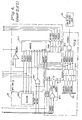
- the output of the units carry flop 76-5, signal CARYFF-, is selected by a MUX 76-40 during the cycle in which the next units digit output of PROM 54-1 is added to the next higher selected digit of the partial product.
- the output of the tens carry flop 76-6, signal TNSCRY-, is selected by MUX 76-40 during the development of the next tens partial product.
- MUX 76-40 selects the units carry output signal CARYFF- when signal CIFRFC- is at logical ONE and signal MULTNS- at logical ONE indicates a units carry, and selects the tens carry output signal TNSCRY- when signal CIFRFC- is at logical ONE and signal MULTNS- at logical ZERO indicates a tens carry.
- the MUX 76-40 output signal ALUCIN- at logical ZERO applied to ALUl 76-2 adds the carry to the arithmetic operation performed by ALUl 76-2.
- a carry output signal ALUCN4- is forced to logical ZERO when a carry results from the arithmetic operation performed on the digits applied to ALUl 76-2.
- Signal ALUCN4- applied to the D terminal conditions flop 76-6 to reset.
- Signal ALUCN4- applied to a NOR gate 76-52 forces signal CRYDEC+ to logical ONE, forcing signal CRYOUT+, the input to terminal D, to logical ONE conditioning flop 76-5 to set.
- Flop 76-5 sets on the rise of clock signal CARYCK- to store the units carry and flop 76-5 resets on the rise of clock signal LDTNSC- to store the tens carry.
- Clock signal CARYCK- the output of negative AND gate 76-64, rises on the rise of clock signal CLOCK2- with signal LDC R YF- at logical ZERO.
- Clock signal LDTNSC- the output of negative AND gate 76-63, rises on the rise of clock signal CLOCK2- with signal MULTNS- at logical ZERO.
- Control store decode logic 61 conditions the setting of units carry flop 76-5 during the processing of a decimal instruction by forcing signal ALUSDO- to logical ZERO, forcing signal CDCRYF- to logical ZERO via a NOR gate 76-62, signal ALSBDO+ and a NAND gate 76-61 with signal MULTNS- at logical ONE. Also, signal ALUSDO+, the output of an inverter 76-66, at logical ONE conditions NOR gate 76-52 to be responsive to carry signal ALUCN4- from ALUl 76-2.
- signal ALUSBO- is forced to logical ZERO to condition the units carry flop 76-5 during the processing of a binary instruction by forcing signal LDCRYF- to logical ZERO and the output of an inverter 76-65, signal ALUSBO+, to logical ONE.
- This conditions a NOR gate 76-51 to be responsive to the ALU2 76-3 carry signal ALUCN8- at logical ZERO to set units carry flop 76-5 via signals CRYOUT+.
- ALU1 76-2 and A LU2 76-3 are coupled together during certain binary instructions and the carry out signal ALUCtN4- of ALU1 76-2 is coupled to the carry in terminal of ALU2 76-3.
- the carry signals CARYFF- and TNSCRY- are applied to input terminals 1 and 3 respectively of MUX 76-40.
- Signal RFCL08- is applied to input terminal 2 from RFC 82-1 when executing the binary hexadecimal conversion to introduce the current binary digit into a decimal doubling algorithm.
- the input terminals are selected by control store decode logic 61 via signals CIFRFC- and MULTNS- applied to select terminals 1 and 2 respectively.
- the units carry signal CARYFF- is selected by forcing signals CIFRFC- and MULTNS- to logical ONE
- the tens carry signal TNSCRY- is selected by forcing signal CIFRFC- to logical ONE and signal MULTNS- to logical ZERO via control store decode logic 61.
- the carry in signal ALUCIN- may be forced to logical ZERO to indicate a carry early in a control cycle by forcing the enable input signal FRCICK+, the output of a NAND gate 76-41, to logical ONE when signal DIROFF- and the clock A+ signals are at logical ZERO. This is required during the divide operation to permit the test if the next subtraction would result in a negative remainder while at the same time the CARYFF+ signal is affecting the next control store address to indicate the success or failure of the previous subtract pass. The test is accomplished by subtracting the most significant digit of the divisor from the most significant digit of the remainder. If the result is negative, then there is no need to go through the full subtraction and add back sequence. During the test, signal ALUCIN- is forced to logical ZERO and forces the ALUl 76-2 resultant output to indicate the subtraction of the terminal B input signals from the terminal A input signals.
- control store decode logic 61 sets tens carry flop 76-6 and resets units carry flop 76-5 to clear the tens and units carry. This occurs near the end of a control cycle -- too late to affect the next control store address if units carry flop 76-5 is being tested and too late to condition ALUl 76-2 reliably for the test described supra.
- OP1A 84 is set to point to the least significant divisor digit in OP1 64 and OP2A 78 is set to point to the decimal digit position that allows the most significant digits of OP1 64 and OP2 66 to be aligned.
- Each divisor digit is subtracted from its respective dividend digit by ALU1 76-2 and the remainder digit is stored back in the dividend digit position in OP2 66.
- the subtraction moves from the least significant digit to the most significant digit as OPlA 84 and OP2A 78 are decremented after each digit subtraction.
- the following simultaneous actions occur:
- the OP2A 78 starting value is incremented by hexadecimal 1 resulting in a one decimal digit position shift. Also, the previous most significant digit of the partial remainder is stored in MIER 52. The contents of ALQR 72 are stored with the rest of the quotient in RFD 50-1 and ALQR 72 is set to decimal ZERO. If another quotient digit is needed, the previous subtraction sequence is repeated. Referring to Figure 5, the test is initiated by forcing signal DIROFF- to logical ZERO. At CLOCKA + time the output of MUX 76-40, signal FRCICK+ at logical ONNE forces the output signal ALUCIN- to logical ZERO, thereby forcing a carry into ALUl 76-2.
- signals AL1DG 0-3+, Figure 3 are applied to terminal B of ALUl 76-2 and the corresponding digit from OP2 66, signals AL2DG 0-3+, is applied to terminal A of ALU1 76-2.
- ALUl 76-2 is programmed to subtract when signals ALUSFO+ and ALUFS3+ are at logical ZERO, signals ALUSFO- and ALUFS1+ are at logical ONE and carry signal ALUCIN- is at logical ZERO. Subtraction is accomplished by the 1's complement addition where the 1's complement of the subtrahend is generated internally in ALUl 76-2.
- the resultant output is A-B-1. Forcing signal ALUCIN- to logical ZERO provides the resultant output of A-B.
- MIER 52 may store the most significant digit of the partial remainder. When the most significant digit of the divisor is subtracted from the next most significant digit of the partial remainder during the full subtraction pass resulting in a negative number, the content of MIER 52 is decremented.
- the divisor is subtracted repeatedly from the partial remainder, decrementing MIER 52 each time a borrow is required.
- MIER 52 stores a decimal ZERO
- the test is made by subtracting the most significant decimal digit of the divisor from the now most significant partial remainder decimal digit to determine if a further subtraction is required to develop the quotient digit stored in ALQR 72.
- step 1 a dividend of 67 is stored in OP2 66 and a divisor of 5 is stored in OP1 64.
- MIER 52 decimal ZERO.
- Flop 76-5 Figure 5
- Terminal 3 of MUX 76-40 is selected since signals CIFRFC- and MULTNS- are at logical ONE and the signal FRCICK+ is at logical ZERO.
- OP1A 84 points to the position of OP1 64 storing the divisor decimal digit 5
- OP2A 78 points to the position of OP2 66 storing the dividend decimal digit 6.
- step 3 the content of ALQR 72 is incremented and stores a quotient digit of decimal 1.
- Test signal FRCICK+ is forced to logical ONE forcing the output signal ALUCIN- to logical ZERO.
- the most significant partial remainder decimal digit 1 is compared with the most significant divisor decimal digit 5 in ALUl 76-2.
- Carry signal ALUCN4- is at logical ONE indicating to the control store addressing logic 78 in step 4 that no further subtractions are required.
- the most significant partial remainder decimal digit 1 is stored in MIER 52 and the initial content of OP2A 78 is incremented to point to the decimal digit 7.
- the quotient decimal digit 1 is stored in ALQR 72 is transferred to scratchpad memory RFD 50-1 during step 5 and ALQR 72 is cleared.
- the state of signal ALUCIN- is immaterial during steps 4 and 5.
- step 6 divisor decimal- digit 5 is subtracted from dividend decimal digit 7.
- the partial remainder decimal digit 2 replaces decimal digit 7 in OP2 66.
- Carry signal ALUCN4- at logical ZERO indicates that the result of the subtraction was a positive number and flop 76-50 remains set.
- step 7 MIER 52 not storing a decimal digit 0 and signal ALUCN4- at logical ZERO in step 6 call for another subtract cycle.
- Signal FRCICK+ forces signal ALUCIN- to logical ZERO.
- ALQR 72 is incremented to store quotient decimal digit 1.
- decimal digit 5 is subtracted from partial remainder decimal digit 2. This results in a partial remainder decimal digit of 7 which replaces the partial remainder decimal digit 2 in OP2 66 and forces signal ALUCN4- to logical ONE, indicating that the subtraction resulted in a negative number.
- Flop 76-50 is reset and signal ALUCIN- is forced to logical ONE.
- step 9 ALQR 72 is incremented and the partial remainder decimal digit 7 is compared with the divisor decimal digit 5.
- Signal FRCICK+ forces signal ALUCIN- to logical ZERO.
- MIER 52 is decremented and stores decimal digit 0.
- Flop 76-50 is set and signal ALUCIN- is forced to logical ZERO.
- the result of the comparison is positive and signal ALUCN4- is at logical ZERO.
- step 11 partial remainder decimal digit 2 replaces decimal digit 7 in OP2 66.
- step 12 ALQR 72 is incremented to store quotient decimal digit 3. Since signal MIEREO+ indicates to control store addressing logic 58, Figure 4, that the content of MIER 52 is decimal ZERO, test signal FRCICK+ is forced to logical ONE, forcing signal ALUCIN- to logical ZERO. Divisor decimal digit 5 is subtracted from partial remainder digit 2. Signal ALUCN4- at logical ONE indicates that the result of the subtraction is a negative number. Signal MIEREO+ at logical ONE and signal ALUCN4- at logical ZERO indicate to control store addressing logic 58 that the divide calculations are completed.
- step 13 the content of ALQR 72, quotient decimal digit 3, is stored in RFD 50-1.
- RFD 50-1 stores the quotient decimal 13 and OP2 66 stores the remainder of decimal 2.
Landscapes
- Engineering & Computer Science (AREA)
- Computing Systems (AREA)
- Physics & Mathematics (AREA)
- General Physics & Mathematics (AREA)
- Theoretical Computer Science (AREA)
- Computational Mathematics (AREA)
- Mathematical Analysis (AREA)
- Mathematical Optimization (AREA)
- Pure & Applied Mathematics (AREA)
- General Engineering & Computer Science (AREA)
- Complex Calculations (AREA)
Abstract
Description
- This invention relates generally to the execution of decimal arithmetic instructions by a commercial instruction processor of a data processing system, and more specifcally to apparatus which, during the execution of a decimal divide instruction by the successive subtraction method, tests the high order positions of the divisor and the remainder to anticipate a negative result of the next subtration.
- Data processing systems commonly perform the decimal divide instruction by successive subtractions of the dividend by the divisor. The subtractions are carried out by aligning the most significant decimal digit positions of the dividend and divisor and subtracting a decimal digit at a time, least significant decimal digit position first. The high order quotient decimal digit is generated by counting the number of subtractions of the dividend by the divisor that gives a positive remainder. A negative subtraction result indicates that no further subtractions are needed, the divisor is added back to the remainder, and the unsuccessful subtraction is not counted.
- The divisor is shifted over one digit position to the right and successive subtractions are made of the remainder to generate the .next lower order quotient decimal digit.
- It was desirable to eliminate the last subtraction and add back steps to reduce the time period for executing the decimal divide instruction.. This was accomplished by comparing the high order decimal digits after a subtraction to anticipate the negative result of the next subtraction. However, this test required a number of steps which reduced the throughput.
- Accordingly, it is a primary object of the present invention to provide a processor having improved apparatus for anticipating the result of a subtraction when executing the decimal divide instruction.
- Accordingly the present invention provides apparatus for performing non-binary division including subtracting means for repeatedly subtracting the contents of a divisor register from the contents of a dividend/partial remainder register, with counter means generating successive quotient digits by counting the number of subtractions resulting in a positive partial remainder, characterized by means for storing the most significant decimal digit of each of the sequence of partial remainders and generating a ZERO signal when its contents are a decimal ZERO, from which a decode signal is generated, the subtracting means including multiplexer means responsive to the decode signal for generating a test signal for determining if the most significant decimal digit of each of the sequence of partial remainders is less than the most significant decimal digit of the divisor for avoiding a subtraction and an add back sequence.
- A data processing system embodying the invention will now be described, by way of example, with reference to the drawings, in which:
- Figure 1 is a block diagram of the overall data processing system.
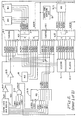
- Figure 2 is a block diagram of the
commercial instruction processor 10. - Figure 3 is a block diagram of that portion of the
CIP 10 that relates to the decimal multiply operation. - Figure 4 is a detailed logic diagram which includes the multiply read only
memory 54 which stores the products and themultiply register 52 which stores the multiplier digit. - Figure 5 is a detailed logic diagram of the carry operation.
- Figure 6 shows the elements of a decimal divide example used to describe the operation of the system.
- A commercial instruction processor executes a decimal divide instruction by storing the divisor in an OP1 register and the dividend in an OP2 register. The content of an OPlA register points to the position of the least significant divisor decimal digit in OP1. The content of an OP2k register points to the decimal digit position in OP2 that aligns the most significant decimal digits of OP1 and OP2.
- An arithmetic logic unit ALUl subtracts each decimal digit in OP1 from the respective decimal digit in OP2 to generate a partial remainder decimal digit which replaces the OP2 decimal digit.
- After the subtraction of the most significant divisor decimal digit in OP1 from the most significant dividend decimal digit in OP2 to generate a most significant partial remainder decimal digit which replaces the most significant dividend decimal digit, a test request signal is applied to a multiplexer. The multiplexer output signal is applied to ALU1 which subtracts the divisor most significant decimal digit from the most significant partial remainder decimal digit in OP2. If the result of the test subtraction is a positive decimal digit, then the divisor in OP1 is subtracted from the partial remainder in OP2. If the result of the test subtraction is a negative number indicating that another complete subtraction cycle of the divisor in OP1 from the partial remainder in OP2 would result in a negative remainder and an add back into OP2, then the following steps are taken. The most significant partial remainder decimal digit is transferred from OP2 to an MIER register. The initial contents of OP2A are incremented by hexadecimal ONE to essentially shift the divisor in OPI one decimal digit position to the right. The quotient digit stored in an ALQR register is stored in a scratchpad memory. The quotient digit stores the number of subtractions of the divisor from the dividend that resulted in a positive partial remainder.
- The divisor in OP1 is now subtracted from the partial remainder in OP2 and the result of the subtraction, the new partial remainder, is stored back in OP2. Each time the result of the subtraction is negative, MIER is decremented by
decimal digit 1. - When MIER stores a
decimal digit 0, then during each subtraction cycle, after the most significant divisor decimal digit in OP1 is subtracted from the most significant partial remainder decimal digit to generate the new most significant partial remainder decimal digit, then the test request signal is applied to the multiplexer. The multiplexer output conditions the ALU to subtract the most significant divisor decimal digit from the new partial remainder most significant digit. A negative answer indicates that this subtraction sequence is completed, the quotient is stored in scratchpad memory, the new partial remainder decimal digit is transferred from OP2 to MIER, and OP2A is incremented. - Figure 1 is an overall block diagram of a data processing system which includes a
main memory 4, a plurality of input/output controllers 6 and a cache/memory management unit (C/MMU) 12; all coupled in common to asystem bus 14. Coupled to the C/MMU 12 are a central processor unit (CPU) 2, a commercial instruction processor (CIP) 10 and a scientific instruction processor (SIP) 8 viabuses MMU 12,CIP 10,CPU 2 andSIP 8 are coupled in common to acommon bus 16. Also,CPU 2 is coupled to theCIP 10 and theSIP 8 viabuses - The
CIP 10 executes a set of instructions designed to facilitate processing of character strings and decimal data. TheSIP 8 executes a set of scientific instructions particularly useful for FORTRAN applications. This set includes arithmetic operations on single and double precision floating point operands and single and double word integer operands. - All instructions in a.program under execution are received by
CPU 2 from C/MMU 12 viabuses CPU 2 determines from the operation code of the instructions if the instruction is to be processed by theCPU 2, theCIP 10, or theSIP 8. TheCPU 2 receives status information from theCIP 10 orSIP 8 overbuses CIP 10 orSIP 3 is available, theCPU 2 sends the necessary information out oncommon bus 16 and alsobus 26 for theSIP 8. The CIP 10 or theSIP 8 processes the instruction and is operative with the C/MMU 12 viabus bus 16 for processing the instruction. - The CIP 10 processes instructions which include the following:
- 1. Decimal arithmetic operations on string and packed numeric data.
- 2. Alphanumeric and decimal move and compare instructions.
- 3. Conversion between binary and decimal numeric representation.
- 4. Edit instructions.
- 5. Arithmetic shift instructions.
-
Main memory 4 stores instructions and data and is operative with the C/MMU 12 for the transferring of instructions and data oversystem bus 14 under control ofCPU 2 viabus 20. - The C/
MMU 12 which includes a cache memory stores the instructions and data currently being processed by theCPU 2,CIP 10 andSIP 8. - The
CPU 2 is also operative for initiating transfers of data between the I/O controllers 6 andmain memory 4. - Referring to Figure 2, all
CIP 10 operations except initialization operations from a console are initiated byCPU 2 writing a 6 bit function code into afunction code register 96 and a 32 bit double word of data into a portion of a commonbus data interface 80 viacommon bus 16. TheCIP 10 when activated transfers thelow order 6 bits of the double word into aninstruction register 56. If the function code register 96 stores an outputtask function code 0716 , then thelow order 16 bits of the double word are stored in a portion of anaddress control unit 82 to allow theCPU 2 to request the previous instruction word at a later time. - The contents of
function code register 96 select a firmware word in acontrol store 60 via controlstore addressing logic 58. The firmware word is loaded into a control store data register 62 and conditions CIP 10 to receive additional control information fromCPU 2. A controlstore decode logic 61 generates control signals by decoding the output signals RD 00-67+ from control store data register 62. Signals RD 52-67+ applied to controlstore addressing logic 58 results incontrol store 60 branching to a specified address location. - The
CIP 10 instructions operate on three data types, decimal strings containing binary coded decimal digits, alphanumeric strings containing ASCII characters and binary numbers having 16 or 32 bit precision. Decimal data operands are referenced by the location of the most significant digit and length and may have one or two digits in a byte. Packed decimal operands store two digits per byte and string decimal operands store one digit per byte. - String decimal operands may be unsigned and assumed positive, may have a leading sign byte placed before the most significant decimal byte, a trailing sign byte placed after the least significant decimal byte or a trailing overpunched sign included with the least significant decimal byte.
- Packed decimal operands may be unsigned implying a positive sign or have a trailing sign.
- Binary data operands have the most significant binary bit as a sign bit with the binary point assumed to the right of the least significant binary bit using 2's complement notation.
- The double words received by
CIP 10 fromCPU 2 following the instruction word specifying a decimal arithmetic operation indicates the decimal type, string or packed, sign information, the length of the operand and tne effective address. This is the address of the byte containing the most significant character (4 or 8 bits/character). - Initially during the processing of a decimal numeric instruction,
control store 60 generates signals via control store data register 62 causing theaddress control unit 82 to send themain memory 4 address of theoperand 1 word containing the sign character to C/MMU 12.- Theoperand 1 word containing the sign character is received by commonbus data interface 80 and stored inOP1 64 andOP2 66. The sign character is selected byselector 70 for transfer to a sign decode overpunch encodelogic 74 where it is decoded into status bits indicating an illegal sign or a negative sign. The controlstore addressing logic 58 is responsive to the illegal sign status bit and the negative sign status bit. If the sign is legal, then the negative sign status bit is stored in themicroprogram status register 94. Theoperand 2 word containing the sign is processed in a similar manner and stored inOP2 66.Selector 70 transfers the sign character to sign decode overpunch encodelogic 74 where it is decoded into the illegal sign or the negative sign and stored in themicroprogram status register 94. This allows theCIP 10 to abort the instruction and notify theCPU 2 if an illegal sign was detected. - A decimal add instruction is indicated by an output task function code, 0716 and the
instruction register 96 storing hexadecimal 2016. During the execution of the decimal add instruction,operand 1 is added tooperand 2 and the result of the addition is stored in the location inmain memory 4 that storedoperand 2. - The
CIP 10 waits for theCPU 2 to send the additional control information required for theCIP 10 to execute the decimal add instruction. Th.e additional control information consists of up to 3 doublewords describing operand 1 and up to 3 doublewords describing operand 2. The last double word received from theCPU 2 is an output last data descriptor indicated by a function code of 1F16. - The first of the 3 double words for each operand contains the effective virtual byte address of the operand which indicates the start of the operand in
main memory 4, that is, the leftmost or lowest addressed byte containing some of the operand. The second double word may contain an indirect length. The third double word contains the data descriptor which specifies the data type and the position within the initial word received frommain memory 4 of the start of the operand. The six double words are stored in theaddress control unit 82. - The output of
instruction register 56 addresses a word incontrol store 60 to start theCIP 10 execution of the decimal add instruction by sending themain memory 4 address for the low order word ofoperand 1 containing the least significant decimal digits to the C/MMU 12 viabus 18. The first word ofoperand 1 is read frommain memory 4 or from a cache memory (not shown) in C/MMU 12 and transferred toCIP 10 viacommon bus 16 and stored inOP1 64. Similarly, the low order word ofoperand 2 is received byCIP 10 and stored indata scratchpad unit 50 and inOP2 66. - The bit of each data descriptor word describing the characteristics of the two operands (ASCII string or packed) and the computed position of the least significant decimal digit in tneir respective low order words for
operands OPlA 84 andOP2A 78 respectively. In addition, the length ofoperands selector 68 and theOP2A 78 output is applied to aselector 70 for selecting theoperand 1 andoperand 2 decimal digits as they are transferred fromOP1 64 andOP2 66 for processing by a decimal/binary ALU 76, one decimal digit at a time. The resulting decimal digit of the addition is transferred fromALU 76 toOP2 66 via an internal bus (BI) 100, replacing theoperand 2 decimal digit that contributed to this result. -
OP1A 84 keeps track of the number of decimal digits remaining inOP1 64 from the transfer of the low order word. When the last decimal digit from the low order word is read fromOP1 64 toALU 76,OPlA 84 signals the branching logic in controlstore addressing logic 58 to address a word incontrol store 60 which fetches the next word ofoperand 1 frommain memory 4 via C/MMU 12. The address of the next word ofoperand 1 is sent fromaddress control unit 82 to C/MMU 12 viabus 18. - Similarly,
OP2A 78 signals the branching logic in controlstore addressing logic 58 to enter into a firmware routine to transfer the resulting word of the addition stored inOP2 66 to common bus data interface 80 for transfer tomain memory 4 viacommon bus 16 to C/MMU 12 at the location specified by the address fromaddress control unit 82 overbus 18. A copy of the result is stored indata scratchpad unit 50. A read cycle is initiated to read the next word ofoperand 2 by sending the next address fromaddress control unit 82 to C/MMU 12 viabus 18. - When the processing of all of the decimal digits from
operand 1 oroperand 2 is completed, descriptor operandlength processing logic 88 controls the filling out of the field of the result in accordance with the remaining decimal digits of the longer operand. Initially during the multiply instruction execution, the entire multiplicand,operand 2, is transferred frommain memory 4 to thedata scratchpad unit 50 via commonbus data interface 80 andBI bus 100. A multiplier double word ofoperand 1 is transferred toOP1 64 via commonbus data interface 80 andBI bus 100. The least significant multiplier digit is read into a multiply register/counter 52 fromOP1 64 viaBI bus 100 and is applied to the input address terminals of a multiply programmable read only memory (PROM) 54. Each double word of the multiplicand in turn is transferred toOP1 64 from thedata scratchpad 50. Each multiplicand digit in turn is applied to tne remaining input address terminals ofPROM 54 fromOP1 64 viaselector 68 to generate the partial product digits. Each partial product digit is applied toALU 76 viaselector 68 where it is added to a corresponding decimal digit stored inOP2 66 and the resultant partial product stored back inOP2 66. - The next multiplier digit is read into multiply register/
counter 52 and the output applied toPROM 54. Again each multiplicand digit in turn is applied toPROM 54 and the partial product digits are applied toALU 76 viaselector 68 where they are added to the selected partial product digits stored inOP2 66. Here again,OP2A 78controls selector 70 to select the partial product digit to be applied toALU 76. The partial product result fromALU 76 is again stored inOP2 66 viaBI bus 100." - When all of the multiplicand digits stored in
data scratchpad unit 50 have been applied to the input address terminals ofPROM 54 along with the most significant multiplier decimal digit output of multiply register/counter 52, thedata scratchpad unit 50 contains the product of the multiplication. This product is written intomain memory 4 viaOP2 66, commonbus data interface 80 andcommon bus 16. - A decimal division instruction is executed by receiving the dividend and divisor in common bus data interface 80 from C/
MMU 12 viacommon bus 16 for storage in thedata scratchpad unit 50. Portions of the divisor are stored inOP1 64 in turn and portions of the dividend/partial remainder are stored inOP2 66 in turn. - The
CIP 10 executes the decimal divide instruction by a series of successive subtractions and counting the number of successful subtractions in an ALQR register/counter 72. A successful subtraction is one in which the result is a positive number. - The divisor in
OP1 64 is applied toALU 76 throughselector 68, a decimal digit at a time, the least significant decimal digit first. The dividend inOP2 66 is applied toALU 76 throughselector 70, a decimal digit at a time.OP2A 78controls selector 70 to select the decimal digit fromOP2 66 that would cause the most significant decimal digits of the divisor inOP1 64 to be aligned with the most significant decimal digit of the dividend for the subtraction operation. - The output of
ALU 76 is stored inOP2 66 viaBI bus 100 and the contents ofALQR 72 are incremented if the result of the subtraction of the high order decimal digits with the divisor is a positive number. The divisor inOP1 64 is again subtracted from the result of the previous subtraction which is stored inOP2 66 and the contents of ALQR 72 again are incremented if the result of the subtraction is positive. - When the result of the subtraction is a negative number, the divisor stored in
OP1 64 is then added toOP2 66 and the contents of ALQR 72 containing a quotient digit are transferred to thedata scratchpad unit 50.OP2 66 anddata scratchpad unit 50 now contain the result of the last successful subtraction in the high order decimal digits and the remaining decimal digits are the original low order decimal digits of the dividend. - The divisor is subtracted from the dividend one digit position to the right of the previous set of subtractions to develop the next quotient digit. The subtraction operation is repeated as described above with
ALQR 72 being incremented for each positive result of the subtraction. - The first quotient digit stored in
data scratchpad unit 50 is transferred toOP2 66 viaBI bus 100. The contents of ALQR 72 containing the second quotient digit is transferred toOP2 66 viaselector 68,ALU 76 andinternal bus 100 where it is appended to the first quotient digit for storage in thedata scratchpad unit 50. The partial dividend is transferred back toOP2 66 from thedata scratcnpad unit 50. - The shifting of the divisor and subsequent subtraction operations are repeated until after computing a quotient digit with the least significant decimal digit of the divisor aligned with the least significant decimal digit of the dividend. The last quotient decimal digit from
ALQR 72 is merged with the rest of the quotient in thedata scratchpad unit 50 and the portion of the remainder now stored inOP2 66 is stored into thedata scratchpad unit 50 viaBI bus 100. The quotient and remainder indata scratchpad unit 50 are then stored inmain memory 4. - A CIP indicator register 90 is set by the control signals to indicate the status of
CIP 10.Register 90 includes an overflow indicator which is set during decimal operations when the receiving field cannot store all significant digits of the result or a divide by zero is detected. A truncation indicator is set during alphanumeric operations when the receiving field cannot contain all characters of the result. A sign fault indicator is set during decimal operations when a negative result is stored in an unsigned field. A greater-than indicator is set during the execution of certain decimal and alphanumeric instructions when the result is greater than zero for decimal numeric operations oroperand 1 is greater thanoperand 2 for decimal or arithmetic comparisons. A less-than indicator is set during the execution of certain decimal and alphanumeric instructions when the result is less than zero for decimal arithmetic instructions oroperand 1 is less thanoperand 2 for either decimal or alphanumeric comparisons. - A CIP mode register 92 stores an overflow trap mask and a truncation trap mask which are indications of which special action the
CIP 10 andCPU 2 should take when the overflow or truncation condition arises. - A
system clock logic 86 includes a 160 nanosecond four phase clock that provides clock signals to trigger allCIP 10 registers and all test and control flops, stabilize registers after loading, signify that address, data, control and parity are valid allowing initiation of a local bus cycle. In addition, thesystem clock logic 86 may be stalled when additional time is required to completecertain CIP 10 functions. Thesystem clock logic 86 generates a BUSY signal overcommon bus 16 to indicate toCPU 2 that theCIP 10 is not available, receives a DCN signal from the C/MMU 12 bus to signal theCIP 10 that data for theCIP 10 is on thecommon bus 8, generates a REQUEST for use of thecommon bus 16, and waits for a GRANT from the C/MMU 12. - The microprocessor status register 94 in addition to storing operand sign information also stores an indication if an overflow was detected in executing a decimal numeric instruction, whether an encode or a decode overpunched sign operation is required, and when a decimal add operation is completed.
- Referring to Figure 3, the
data scratchpad unit 50 includes a register file D (RFD) 50-1, a register/counter (AA) 50-2, a register/counter (AB) 50-3 and a MUX 50-4. RFD 50-1 includes 8 4-bit random access memories organized to store 16 32-bit double words. RFD 50-1 is addressed from either AA 50-2 via signals RFDAA 0-3+, MUX 50-4 and signals RFDAD 0-3+, or from AB 50-3 via signals RFDAB 0-3+, MUX 50-4 and signals RFDAD 0-3+. RFD 50-1 is coupled toBI bus 100 via signals BIDT 00-31-. AA 50-2 and AB 50-3 are loaded fromBI bus 100 via signals BIDT 8-11+. During the decimal multiply operation, AA 50-2 stores the location in RFD 50-1 of the multiplicand words and AB 50-3 stores the location of the partial product words. - The descriptor operand
length processing logic 88 includes acounter 1 88-1, acounter 2 88-2 and acounter 3 88-3 coupled to a MUX 88-4 via signals CTR1 0-3+, CTR2 0-3+ and CTR3 0-3+ respectively; and coupled to a MUX 88-5 via signals CTR1 4-7+, CTR2 4-7+ and CTR3 4-7+ respectively. Signals RD 16-19+ are applied to MUX 88-4 and signals RD 20-23+ are applied to MUX 88-5 to provide miscellaneous constants for transfer ontoBI bus 100. Output signals CTKT 0-3+ of MUX 88-4 are coupled to their respective signals CTBI 0-3+. Output signals CTKT 4-7+ of MUX 88-5 are coupled to their respective signals CTBI 4-7+. Signals CTBI 0-3+ are coupled through MUX 76-11 toBI bus 100 signals BIDT 0-3+, BIDT 8-11+, BIDT 16-19+ and BIDT 24-27+ respectively. Signals CTBI 4-7+ are coupled through MUX 76-11 toBI bus 100 signals BIDT 4-7+, BIDT 12-15+, BIDT 20-23+ and BIDT 28-31+ respectively.Counter 1 88-1,counter 2 88-2 andcounter 3 88-3 are loaded fromBI bus 100 via signals BIDT 16-23+. During a portion of the decimal multiply operation, counter 1 88-1 stores the number of decimal digits inoperand 1, andcounter 2 88-2 stores the number of decimal digits inoperand 2. During another portion of the decimal multiply operation, counter 1 88-1 andcounter 2 88-2 store the number of multiplicand decimal digits remaining to be applied to multiplyPROM 54 for the multiplier digit stored in multiply register (MIER) 52.Counter 3 88-3 may store the number of decimal digits of the multiplier remaining for processing or the effective length of the multiplicand. - The
decimal binary ALU 76 includes a 4-bit arithmetic logic unit (ALU1) 76-2 for processing decimal numeric arithmetic operations and a 4-bit arithmetic logic unit (ALU2) 76-3 for processing alphanumeric operations and code conversions such as binary to decimal and decimal to binary. The ALU1 output signals ALUDG 0-3+ are applied to a MUX 76-8, a MUX 76-9 and a decimal correction unit 76-7. Output signalsALXS OP1 64 are applied to MUX 76-11 as are the output signals OP2D 00-31+ fromOP2 66. The outputs ofOP1A 84 andOP2A 78, signals OP1AD 0-2+, OP1TYP+, OP2AD 0-2+ and OP2TYP+, are applied to MUX 76-11 and appear at the MUX 76-11 output as signals BIDT 12-15+. Also applied to MUX 76-11 are signals ALQR+ fromALQR 72 and MIER+ fromMIER 52 and appear at the MUX 76-11 output as signal BIDT 28-31+ and BIDT 20-23+. - The output of ALU2 76-3, signals ALUZN 0-3+, is applied to a MUX 76-10. Also, a hexadecimal 3 is applied to MUX 76-10 whose output signals ALZON 0-3+ are applied to MUX 75-11.
- A register file C (RFC) 82-1 is coupled to the
BI bus 100. Selected signals ofBI bus 100, BIDT 00-31+, are stored in positions A,0-23 of RFC 82-1. The logic selecting the input bit positions is not shown since it is not pertinent to the invention. Output signals RFC A,0-23+ from RFC 82-1 are applied to MUX 76-11 and appear onBI bus 100 as signals BIDT 7-31+. - A units carry 76-5 and a tens carry 76-6 are coupled to ALU1 76-2 via a MUX 76-4. During the decimal multiply operation, the units carry 76-5 is operative when the multiply
PROM 54 generates the units position decimal digit and the tens carry 76-6 is operative when the multiplyPROM 54 generates the tens position decimal digit. - During the decimal multiply operation, a double word of the partial product is stored in
OP2 66 and a double word of the multiplicand is stored inOP1 64. TheOP2 66 output signals OP2D 00-31+ are applied toselector 70. TheOP2A 78 output signals OP2AD 0-2+ and OP2TYP+ enableselector 70 to transfer the selected decimal digit to terminal A of ALU1 76-2 via signals AL2DGO+. TheOP1A 84 output signals OP1AD 0-2+ and OP1TYP+ enableselector 68 to transfer the selected multiplicand digit, received via signals OP1X 00-31+, to multiplyPROM 54 via signals OP1DG 0-3+. The output of multiplyPROM 54, signals MULDG 0-3+, is applied to terminal B of ALU1 76-2 as signals ALlDG 0-3+. The sum is transferred back toOP2 66 in the selected partial product digit position via MUX's 76-8 or 76-9 and MUX 76-11 viaBI bus 100. - A MUX 68-1 transfers the output of
ALQR 72, signals ALQR 0-3+, or the output of selector 68-2, signals OP1DG 0-3+, to terminal B of ALU1 76-2 via signals OP1QD 0-3+ and AL1DG 0-3+. Typically, anoperand 1 decimal digit inOP1 64 or RFD 50-1 and anoperand 2 decimal digit inOP2 66 may be combined in ALU1 76-2 or the contents of ALQR 72 may be combined with a selected decimal digit position inOP2 66 during a divide operation. - RFC 82-1 of the
address control unit 82 stores the instruction and the data descriptors describing the characteristics of the operands. RFC 82-1 is made up of 6 4-bit random access memories and a portion of a seventh random access memory organized as 16 25-bit words. Certain locations of RFC 82-1 are used as a scratchpad memory to temporarily store the contents of the various register/counters including AA 50-2, AB 50-3,counter 1 88-1,counter 2 88-2 andcounter 3 88-3. - The decimal correction 76-7 is active during the arithmetic operation. BCD coded decimal digits are added by first modifying the selected
OP2 66 digit inselector 70 by increasing its binary value by 6 (excess 6 code). When the modifiedOP2 66 digit (appearing as signals AL2DG 0-3+) is added to the unmodified digit selected fromOP1 64 by the binary ALU1 76-2, the binary carry out of ALU1 76-2 is equivalent to a decimal carry. If a carry out is asserted, then the output of ALU1 76-2 appearing on signals ALUDG 0-3+ is the correct BCD representation of the sum. If carry out is not asserted, then ALUDG 0-3+ is an excess 6 representation of the sum and the decimal correction logic is activated to reduce this sum by 6 to produce the correct BCD representation. - Referring to Figure 4, the multiply
PROM 54 includes a read only memory (PROM) 54-1 and a negative logic OR gate 54-2 which enables the PROM 54-1 via signal MULENB-. PROM 54-1 has the capacity for storing 512 decimal digits, 256 units position decimal digits and 256 tens position decimal digits. - The multiply
register 52 includes a register/counter 52-1, a negative logic OR gate 52-3 and a not AND gate 52-2. The register/counter 52-1 stores each multiplier digits in turn from the least significant multiplier digit to the most significant multiplier digit. The register/counter 52-1 is also used as a counter by theCIP 10 during the setup of the decimal multiply operation to store a count of the number of multiplicand double words that remain inmain memory 4 prior to transfer to theCIP 10. The selector 68-2 includes the MUX 63-1. Theselector 68 applies a selected multiplicand digit over signals OP1DG 0-3+ to the 8, 4, 2 and 1 input address terminals of PROM 54-1. The register/counter 52-1 applies the multiplier digit over signal lines MIER 0-3+ to the 128, 64, 32 and 16 input address terminals ofPROM 54. The units position of the product appears on output signals MULDG 0-3+ when the PROM 54-1 is enabled by signal MULENB- at logical ZERO and signal MULUNT- at logical ZERO. The tens position of the product appears on the output signals MULDG 0-3+ when PROM 54-1 is enabled and signal MULUNT- is at logical ONE. - The Boolean equation for signal MULUNT- at logical ZERO is:

- Either the tens multiplication signal MULTNS- or the units multiplication signal MULUNT- at logical ZERO applied to negative logic OR gate 54-2 enables PROM 54-1 by forcing signal MULENB- to logical ZERO.
- The Boolean equation for signal MULTNS- at logical ZERO is:
-

- Register/counter 52-1 is operative as a counter when keeping track of the number of double words of the multiplicand remaining in
main memory 4 when theCIP 10 is being conditioned to perform the decimal multiply instruction. Register/counter 52-1 is decremented at CLOCK2- time when logic signal DCMIER- is at logical ZERO, forcing the output of NOR gate 52-3, enable signal MIERCT-, to logical ZERO and enabling the -1 terminal. - The Boolean equation for signal DCMIER- at logical ZERO is:

- When register/counter 52-1 is decremented to hexadecimal ZERO, signal MIEREO+ is forced to logical ONE, thereby signalling the control
store addressing logic 58 that the transfer of multiplier double words frommain memory 4 is concluded after the next transfer. - Register/counter 52-1 is loaded with the number of double words and each multiplier hexadecimal digit in turn from
BI bus 100 at CLOCK2- time when signal MIERLD- is at logical ZERO. - Signal MIERLD- is applied to the LOAD terminal of register/counter 52-1.
- The Boolean equation for signal MIERLD- at logical ZERO is:

- A multiplier digit of hexadecimal ZERO forces signal MIEREO+ to logical ONE which signals the control
store addressing logic 58 to bring in the next multiplier hexadecimal digit into register/counter 52-1. - MUX 76-1 provides a high impedance for signals OP1QD 0-3+ when the enable signal output of an inverter 54-3, MULEN3+, is at logical ONE. The PROM 54-1 is enabled since signal MULENB- is at logical ZERO and output signals MULDG 0-3+ appear on signal lines ALlDG0+. During the loading of register/counter 52-1, the hexadecimal digit is transferred from
OP1 64 in Figure 3,selector 68, MUX 76-1, ALUl 76-2, MUX 76-9, MUX 76-11 andBI bus 100 signals BIDT 20-23+. - Referring to Figure 4, output signals OPlDG 0-3+ are applied to
terminal 1 of MUX 76-1. Output signals OP1QD 0-3+ are applied to terminal B of ALUl 76-2 via signals AL1DG 0-3+. Signal AQRSEL- is at logical ONE and signal MULENB+ is at logical ZERO. - The Boolean equation for AQRSEL- at logical ONE is:

- The
ALQR 72 signals ALQR 0-3+ are applied to theterminal 0 of MUX 76-1. - It should be noted that the sequences of operation are controlled by the output signals RD 00-67+ from control store data register 62, Figure 2. The control signals described by the Boolean equations are output signals from control
store decode logic 61. (The Boolean notation [RD08 . (RD09 + RD10)] indicates an output of logical ONE when signal RD08 is at logical ONE and either or both signal RD09 is at logical ZERO or signal RD10 is at logical ONE.) - Figure 5 shows the detailed carry logic associated with ALU1 76-2 and ALU2 76-3. The decimal multiply operation uses the PROM 54-1 of Figure 4 to read out the units digit and the tens digit for each multiplicand and multiplier digit. The partial product is developed by adding the units digit to a selected digit of the partial product and setting a units carry flop 76-5 if a carry resulted, and adding the tens digit to a next higher selected digit of the partial product and setting a tens carry flop 76-6 if a carry resulted. The output of the units carry flop 76-5, signal CARYFF-, is selected by a MUX 76-40 during the cycle in which the next units digit output of PROM 54-1 is added to the next higher selected digit of the partial product. The output of the tens carry flop 76-6, signal TNSCRY-, is selected by MUX 76-40 during the development of the next tens partial product.
- MUX 76-40 selects the units carry output signal CARYFF- when signal CIFRFC- is at logical ONE and signal MULTNS- at logical ONE indicates a units carry, and selects the tens carry output signal TNSCRY- when signal CIFRFC- is at logical ONE and signal MULTNS- at logical ZERO indicates a tens carry. The MUX 76-40 output signal ALUCIN- at logical ZERO applied to ALUl 76-2 adds the carry to the arithmetic operation performed by ALUl 76-2. A carry output signal ALUCN4- is forced to logical ZERO when a carry results from the arithmetic operation performed on the digits applied to ALUl 76-2. Signal ALUCN4- applied to the D terminal conditions flop 76-6 to reset. Signal ALUCN4- applied to a NOR gate 76-52 forces signal CRYDEC+ to logical ONE, forcing signal CRYOUT+, the input to terminal D, to logical ONE conditioning flop 76-5 to set. Flop 76-5 sets on the rise of clock signal CARYCK- to store the units carry and flop 76-5 resets on the rise of clock signal LDTNSC- to store the tens carry.
- Clock signal CARYCK-, the output of negative AND gate 76-64, rises on the rise of clock signal CLOCK2- with signal LDCRYF- at logical ZERO. Clock signal LDTNSC-, the output of negative AND gate 76-63, rises on the rise of clock signal CLOCK2- with signal MULTNS- at logical ZERO.
- Control
store decode logic 61 conditions the setting of units carry flop 76-5 during the processing of a decimal instruction by forcing signal ALUSDO- to logical ZERO, forcing signal CDCRYF- to logical ZERO via a NOR gate 76-62, signal ALSBDO+ and a NAND gate 76-61 with signal MULTNS- at logical ONE. Also, signal ALUSDO+, the output of an inverter 76-66, at logical ONE conditions NOR gate 76-52 to be responsive to carry signal ALUCN4- from ALUl 76-2. Similarly, signal ALUSBO- is forced to logical ZERO to condition the units carry flop 76-5 during the processing of a binary instruction by forcing signal LDCRYF- to logical ZERO and the output of an inverter 76-65, signal ALUSBO+, to logical ONE. This conditions a NOR gate 76-51 to be responsive to the ALU2 76-3 carry signal ALUCN8- at logical ZERO to set units carry flop 76-5 via signals CRYOUT+. Also, ALU1 76-2 and ALU2 76-3 are coupled together during certain binary instructions and the carry out signal ALUCtN4- of ALU1 76-2 is coupled to the carry in terminal of ALU2 76-3. - The carry signals CARYFF- and TNSCRY- are applied to input
terminals - The input terminals are selected by control
store decode logic 61 via signals CIFRFC- and MULTNS- applied to selectterminals store decode logic 61. - The carry in signal ALUCIN- may be forced to logical ZERO to indicate a carry early in a control cycle by forcing the enable input signal FRCICK+, the output of a NAND gate 76-41, to logical ONE when signal DIROFF- and the clock A+ signals are at logical ZERO. This is required during the divide operation to permit the test if the next subtraction would result in a negative remainder while at the same time the CARYFF+ signal is affecting the next control store address to indicate the success or failure of the previous subtract pass. The test is accomplished by subtracting the most significant digit of the divisor from the most significant digit of the remainder. If the result is negative, then there is no need to go through the full subtraction and add back sequence. During the test, signal ALUCIN- is forced to logical ZERO and forces the ALUl 76-2 resultant output to indicate the subtraction of the terminal B input signals from the terminal A input signals.
- The CRYCLR- signal generated by control
store decode logic 61 sets tens carry flop 76-6 and resets units carry flop 76-5 to clear the tens and units carry. This occurs near the end of a control cycle -- too late to affect the next control store address if units carry flop 76-5 is being tested and too late to condition ALUl 76-2 reliably for the test described supra. - The Boolean expressions for the control store decode logic signals are:





- As described supra for the decimal divide instruction, assume initially that the entire divisor is stored in
OP1 64, Figure 3, and that the entire dividend is stored inOP2 66. (The full division algorithm uses RFD 50-1 to hold the operands, each of which may be 31 digits long. The proper moving of operands betweenOP1 64,OP2 66 and RFD 50-1 make a full subtraction pass and an add-back pass very expensive in time.)OP1A 84 is set to point to the least significant divisor digit inOP1 64 andOP2A 78 is set to point to the decimal digit position that allows the most significant digits ofOP1 64 andOP2 66 to be aligned. - Each divisor digit is subtracted from its respective dividend digit by ALU1 76-2 and the remainder digit is stored back in the dividend digit position in
OP2 66. The subtraction moves from the least significant digit to the most significant digit asOPlA 84 andOP2A 78 are decremented after each digit subtraction. At the end of a full subtraction pass, the following simultaneous actions occur: - 1. The success or failure of the full subtract pass which is implied by the final state of the units carry flop 76-5 and whether
MIER 52 does or does not contain decimal ZERO selects one of fourcontrol store 60 addresses indicating the next state of the machine. - 2.
ALQR 72 is incremented -- anticipating that the subtract pass was successful. - 3. Units carry flop 76-5 is set by signal CRYSET- at logical ZERO near the end of the control cycle -- too late for this to affect the
control store 60 address selection. This setting of the units carry flop 76-5 is in anticipation of the need for another full subtract pass. - 4. The most significant digit of the divisor and the corresponding digit of the new partial remainder are compared. This comparison is meaningful only if
MIER 52 contains a decimal ZERO and the previous full subtract resulted in a positive partial remainder, or ifMIER 52 contains a decimal ONE and the previous full subtract pass resulted in a negative partial remainder. This comparison indicates that a subsequent subtract pass must fail if the most significant digit of the divisor is greater than the corresponding digit of the partial remainder. The timing of this test requires that the ALU1 76-2 carry-in signal ALUCIN- be at logical ZERO. This eventually happens as a result of action above, but too late to generate a valid ALUCN4- (the result of the comparison which is sampled at the end of every control cycle); therefore, ALUCIN- is forced low early in the control cycle by logic signal FRCICK+ at logical ONE. - If the subtraction pass resulted in a positive partial remainder and
MIER 52 does not contain a decimal ZERO, then another full subtraction pass is made. If the full subtraction pass resulted in a positive partial remainder andMIER 52 contained a decimal ZERO, then the result of the one digit comparison is tested: - A. If the most significant digit of the divisor is less than or equal to the corresponding digit of the new partial remainder, then another full subtract pass is required;
- B. If the most significant digit of the divisor is greater than the corresponding digit of the new partial remainder, then a quotient digit in
ALQR 72 is stored in RFD 50-1, the divisor is shifted, and a new series of subtractions is started. - If the full subtract pass resulted in a negative partial remainder and
MIER 52 does not contain either decimal ZERO or decimal ONE, thenMIER 52 is decremented and the series of subtractions of the partial remainder by the divisor are repeated. If the full subtract pass resulted in a negative partial remainder andMIER 52 contains a decimal ONE, thenMIER 52 is decremented and the result of the one digit comparison is tested as previously described. If the subtract pass resulted in a negative partial remainder andMIER 52 contains a decimal ZERO, then the following actions are taken: -
A. Decrement ALQR 72; - B. Perform an add back of the divisor in
OP1 64 intoOP2 66. - The
OP2A 78 starting value is incremented by hexadecimal 1 resulting in a one decimal digit position shift. Also, the previous most significant digit of the partial remainder is stored inMIER 52. The contents ofALQR 72 are stored with the rest of the quotient in RFD 50-1 andALQR 72 is set to decimal ZERO. If another quotient digit is needed, the previous subtraction sequence is repeated. Referring to Figure 5, the test is initiated by forcing signal DIROFF- to logical ZERO. At CLOCKA + time the output of MUX 76-40, signal FRCICK+ at logical ONNE forces the output signal ALUCIN- to logical ZERO, thereby forcing a carry into ALUl 76-2. The most significant divisor digit, signals AL1DG 0-3+, Figure 3, are applied to terminal B of ALUl 76-2 and the corresponding digit fromOP2 66, signals AL2DG 0-3+, is applied to terminal A of ALU1 76-2. ALUl 76-2 is programmed to subtract when signals ALUSFO+ and ALUFS3+ are at logical ZERO, signals ALUSFO- and ALUFS1+ are at logical ONE and carry signal ALUCIN- is at logical ZERO. Subtraction is accomplished by the 1's complement addition where the 1's complement of the subtrahend is generated internally in ALUl 76-2. The resultant output is A-B-1. Forcing signal ALUCIN- to logical ZERO provides the resultant output of A-B. - If the result of the subtraction is a positive number as indicated by carry out signal ALUCN4- at logical ZERO setting a history flop (not shown) in control
store addressing logic 58 which is tested immediately following the control cycle, then the divisor is again subtracted from the partial remainder inOP2 66. - If the result of the subtraction is a negative number as indicated by carry out signal ALUCN4- at logical ONE, then another subtraction sequence of the divisor in
OP1 64 from the partial remainder inOP2 66 is not required andOPlA 84 is reset to point to the least significant divisor digit andOP2A 78 is reset to point to the partial remainder digit which essentially shifts the divisor one position to the right to prepare for the generation of next quotient digit inALQR 72. - During the generation of the next quotient digit,
MIER 52 may store the most significant digit of the partial remainder. When the most significant digit of the divisor is subtracted from the next most significant digit of the partial remainder during the full subtraction pass resulting in a negative number, the content ofMIER 52 is decremented. - The divisor is subtracted repeatedly from the partial remainder, decrementing
MIER 52 each time a borrow is required. WhenMIER 52 stores a decimal ZERO, the test is made by subtracting the most significant decimal digit of the divisor from the now most significant partial remainder decimal digit to determine if a further subtraction is required to develop the quotient digit stored inALQR 72. - As an example as shown in Figure 6,
step 1, a dividend of 67 is stored inOP2 66 and a divisor of 5 is stored inOP1 64. Initially, the contents ofMIER 52 are decimal ZERO. Flop 76-5, Figure 5, is set since signal CRYSET- is forced to logical ZERO, forcing signal CARYFF- to logical ZERO.Terminal 3 of MUX 76-40 is selected since signals CIFRFC- and MULTNS- are at logical ONE and the signal FRCICK+ is at logical ZERO. This forces the carry signal ALUCIN- to logical ZERO.OP1A 84 points to the position ofOP1 64 storing the divisordecimal digit 5 andOP2A 78 points to the position ofOP2 66 storing the dividenddecimal digit 6. - As a result of the subtraction in ALUl 76-2 of
decimal digit 6 bydecimal digit 5 shown instep 2, the partial remainderdecimal digit 1 replaces thedecimal digit 6 inOP2 66. Carry signal ALUCN4- from ALUl 76-2 at logical ZERO indicates a positive partial remainder. This is copied into units carry flop 76-50. - In
step 3, the content ofALQR 72 is incremented and stores a quotient digit ofdecimal 1. Test signal FRCICK+ is forced to logical ONE forcing the output signal ALUCIN- to logical ZERO. The most significant partial remainderdecimal digit 1 is compared with the most significant divisordecimal digit 5 in ALUl 76-2. Carry signal ALUCN4- is at logical ONE indicating to the controlstore addressing logic 78 instep 4 that no further subtractions are required. The most significant partial remainderdecimal digit 1 is stored inMIER 52 and the initial content ofOP2A 78 is incremented to point to thedecimal digit 7. - The quotient
decimal digit 1 is stored inALQR 72 is transferred to scratchpad memory RFD 50-1 duringstep 5 andALQR 72 is cleared. The state of signal ALUCIN- is immaterial duringsteps - During
step 6, divisor decimal-digit 5 is subtracted from dividenddecimal digit 7. The partial remainderdecimal digit 2 replacesdecimal digit 7 inOP2 66. Carry signal ALUCN4- at logical ZERO indicates that the result of the subtraction was a positive number and flop 76-50 remains set. - During
step 7,MIER 52 not storing adecimal digit 0 and signal ALUCN4- at logical ZERO instep 6 call for another subtract cycle. Signal FRCICK+ forces signal ALUCIN- to logical ZERO.ALQR 72 is incremented to store quotientdecimal digit 1. - During
step 8,decimal digit 5 is subtracted from partial remainderdecimal digit 2. This results in a partial remainder decimal digit of 7 which replaces the partial remainderdecimal digit 2 inOP2 66 and forces signal ALUCN4- to logical ONE, indicating that the subtraction resulted in a negative number. Flop 76-50 is reset and signal ALUCIN- is forced to logical ONE. - During
step 9,ALQR 72 is incremented and the partial remainderdecimal digit 7 is compared with the divisordecimal digit 5. Signal FRCICK+ forces signal ALUCIN- to logical ZERO. - During
step 10,MIER 52 is decremented and storesdecimal digit 0. Flop 76-50 is set and signal ALUCIN- is forced to logical ZERO. The result of the comparison is positive and signal ALUCN4- is at logical ZERO. - During
step 11, partial remainderdecimal digit 2 replacesdecimal digit 7 inOP2 66. - During
step 12,ALQR 72 is incremented to store quotientdecimal digit 3. Since signal MIEREO+ indicates to controlstore addressing logic 58, Figure 4, that the content ofMIER 52 is decimal ZERO, test signal FRCICK+ is forced to logical ONE, forcing signal ALUCIN- to logical ZERO. Divisordecimal digit 5 is subtracted frompartial remainder digit 2. Signal ALUCN4- at logical ONE indicates that the result of the subtraction is a negative number. Signal MIEREO+ at logical ONE and signal ALUCN4- at logical ZERO indicate to controlstore addressing logic 58 that the divide calculations are completed. - During
step 13, the content ofALQR 72, quotientdecimal digit 3, is stored in RFD 50-1. RFD 50-1 stores the quotient decimal 13 andOP2 66 stores the remainder ofdecimal 2.
Claims (3)
Applications Claiming Priority (2)
| Application Number | Priority Date | Filing Date | Title |
|---|---|---|---|
| US219638 | 1980-12-24 | ||
| US06/219,638 US4384341A (en) | 1980-12-24 | 1980-12-24 | Data processor having carry apparatus supporting a decimal divide operation |
Publications (2)
| Publication Number | Publication Date |
|---|---|
| EP0056525A1 true EP0056525A1 (en) | 1982-07-28 |
| EP0056525B1 EP0056525B1 (en) | 1989-10-18 |
Family
ID=22820107
Family Applications (1)
| Application Number | Title | Priority Date | Filing Date |
|---|---|---|---|
| EP81306019A Expired EP0056525B1 (en) | 1980-12-24 | 1981-12-22 | Division system |
Country Status (6)
| Country | Link |
|---|---|
| US (1) | US4384341A (en) |
| EP (1) | EP0056525B1 (en) |
| JP (1) | JPS57172447A (en) |
| AU (1) | AU554993B2 (en) |
| CA (1) | CA1170372A (en) |
| DE (1) | DE3177206D1 (en) |
Cited By (1)
| Publication number | Priority date | Publication date | Assignee | Title |
|---|---|---|---|---|
| GB2239536A (en) * | 1989-11-15 | 1991-07-03 | United Technologies Corp | Binary division of signed operands |
Families Citing this family (17)
| Publication number | Priority date | Publication date | Assignee | Title |
|---|---|---|---|---|
| US4503512A (en) * | 1982-02-22 | 1985-03-05 | Amdahl Corporation | Cellular division circuit |
| US4589087A (en) * | 1983-06-30 | 1986-05-13 | International Business Machines Corporation | Condition register architecture for a primitive instruction set machine |
| US4672360A (en) * | 1983-09-30 | 1987-06-09 | Honeywell Information Systems Inc. | Apparatus and method for converting a number in binary format to a decimal format |
| US4638450A (en) * | 1983-09-30 | 1987-01-20 | Honeywell Information Systems Inc. | Equal nine apparatus for supporting absolute value subtracts on decimal operands of unequal length |
| US4615016A (en) * | 1983-09-30 | 1986-09-30 | Honeywell Information Systems Inc. | Apparatus for performing simplified decimal multiplication by stripping leading zeroes |
| US4608659A (en) * | 1983-09-30 | 1986-08-26 | Honeywell Information Systems Inc. | Arithmetic logic unit with outputs indicating invalid computation results caused by invalid operands |
| US4604722A (en) * | 1983-09-30 | 1986-08-05 | Honeywell Information Systems Inc. | Decimal arithmetic logic unit for doubling or complementing decimal operand |
| US4604695A (en) * | 1983-09-30 | 1986-08-05 | Honeywell Information Systems Inc. | Nibble and word addressable memory arrangement |
| US4942547A (en) * | 1985-04-11 | 1990-07-17 | Honeywell Bull, Inc. | Multiprocessors on a single semiconductor chip |
| US4799181A (en) * | 1986-09-30 | 1989-01-17 | Honeywell Bull Inc. | BCD arithmetic using binary arithmetic and logical operations |
| DE4215563A1 (en) * | 1992-05-12 | 1993-11-18 | Trw Repa Gmbh | Lock for vehicle seat belt systems |
| US6173305B1 (en) | 1993-11-30 | 2001-01-09 | Texas Instruments Incorporated | Division by iteration employing subtraction and conditional source selection of a prior difference or a left shifted remainder |
| US5442581A (en) * | 1993-11-30 | 1995-08-15 | Texas Instruments Incorporated | Iterative division apparatus, system and method forming plural quotient bits per iteration |
| US5644524A (en) * | 1993-11-30 | 1997-07-01 | Texas Instruments Incorporated | Iterative division apparatus, system and method employing left most one's detection and left most one's detection with exclusive or |
| US6067617A (en) * | 1998-04-07 | 2000-05-23 | International Business Machines Corporation | Specialized millicode instructions for packed decimal division |
| US7197526B1 (en) * | 1999-05-28 | 2007-03-27 | Lucent Technologies Inc. | Method and apparatus for calculating the remainder of a modulo division |
| US7149767B2 (en) * | 2003-05-12 | 2006-12-12 | International Business Machines Corporation | Method and system for determining quotient digits for decimal division in a superscaler processor |
Citations (2)
| Publication number | Priority date | Publication date | Assignee | Title |
|---|---|---|---|---|
| FR1050359A (en) * | 1951-10-04 | 1954-01-07 | Bull Sa Machines | Electronic pulse circulation calculator |
| GB1166593A (en) * | 1967-03-02 | 1969-10-08 | Ibm | Data Processing Apparatus |
Family Cites Families (6)
| Publication number | Priority date | Publication date | Assignee | Title |
|---|---|---|---|---|
| US2924383A (en) * | 1953-12-11 | 1960-02-09 | Weiss Eric | Circuitry for multiplication and division |
| US2932450A (en) * | 1954-09-17 | 1960-04-12 | Int Computers & Tabulators Ltd | Electronic calculating apparatus |
| US3239654A (en) * | 1961-02-08 | 1966-03-08 | Ibm | Dividing computer |
| US3591786A (en) * | 1967-01-13 | 1971-07-06 | Ibm | Predicted iteration in decimal division |
| NL7101257A (en) * | 1971-01-30 | 1972-08-01 | ||
| JPS5551219A (en) * | 1978-10-11 | 1980-04-14 | Isamu Saito | Smokeless refuse incinerator |
-
1980
- 1980-12-24 US US06/219,638 patent/US4384341A/en not_active Expired - Fee Related
-
1981
- 1981-12-09 CA CA000391907A patent/CA1170372A/en not_active Expired
- 1981-12-22 EP EP81306019A patent/EP0056525B1/en not_active Expired
- 1981-12-22 DE DE8181306019T patent/DE3177206D1/en not_active Expired - Lifetime
- 1981-12-23 AU AU78847/81A patent/AU554993B2/en not_active Ceased
- 1981-12-24 JP JP56208245A patent/JPS57172447A/en active Pending
Patent Citations (2)
| Publication number | Priority date | Publication date | Assignee | Title |
|---|---|---|---|---|
| FR1050359A (en) * | 1951-10-04 | 1954-01-07 | Bull Sa Machines | Electronic pulse circulation calculator |
| GB1166593A (en) * | 1967-03-02 | 1969-10-08 | Ibm | Data Processing Apparatus |
Cited By (2)
| Publication number | Priority date | Publication date | Assignee | Title |
|---|---|---|---|---|
| GB2239536A (en) * | 1989-11-15 | 1991-07-03 | United Technologies Corp | Binary division of signed operands |
| GB2239536B (en) * | 1989-11-15 | 1994-05-11 | United Technologies Corp | Binary division of signed operands |
Also Published As
| Publication number | Publication date |
|---|---|
| JPS57172447A (en) | 1982-10-23 |
| EP0056525B1 (en) | 1989-10-18 |
| AU7884781A (en) | 1982-07-01 |
| CA1170372A (en) | 1984-07-03 |
| US4384341A (en) | 1983-05-17 |
| AU554993B2 (en) | 1986-09-11 |
| DE3177206D1 (en) | 1990-09-20 |
Similar Documents
| Publication | Publication Date | Title |
|---|---|---|
| EP0056525B1 (en) | Division system | |
| US4390961A (en) | Data processor performing a decimal multiply operation using a read only memory | |
| US4384340A (en) | Data processor having apparatus for controlling the selection of decimal digits of an operand when executing decimal arithmetic instructions | |
| US4484300A (en) | Data processor having units carry and tens carry apparatus supporting a decimal multiply operation | |
| US4426680A (en) | Data processor using read only memories for optimizing main memory access and identifying the starting position of an operand | |
| US4447870A (en) | Apparatus for setting the basic clock timing in a data processing system | |
| US4247891A (en) | Leading zero count formation | |
| US4462072A (en) | Clock system having a stall capability to enable processing of errors | |
| US4423483A (en) | Data processor using a read only memory for selecting a part of a register into which data is written | |
| US3234367A (en) | Quotient guess divider | |
| US4410984A (en) | Diagnostic testing of the data path in a microprogrammed data processor | |
| US4799181A (en) | BCD arithmetic using binary arithmetic and logical operations | |
| US4486848A (en) | Microprocessor parallel additive execution of a computer count ones instruction | |
| US4228518A (en) | Microprocessor having multiply/divide circuitry | |
| US4246644A (en) | Vector branch indicators to control firmware | |
| JPS5829538B2 (en) | floating point arithmetic unit | |
| US4942547A (en) | Multiprocessors on a single semiconductor chip | |
| US4245328A (en) | Binary coded decimal correction apparatus for use in an arithmetic unit of a data processing unit | |
| US3578961A (en) | Preconditioned divisor for expedite division by successive subtraction | |
| US4295202A (en) | Hexadecimal digit shifter output control by a programmable read only memory | |
| US4240144A (en) | Long operand alignment and merge operation | |
| US3508037A (en) | Decimal add/subtract circuitry | |
| EP0055128B1 (en) | Data processing system | |
| US3319057A (en) | Parallel division with separate carry storage | |
| EP0258051B1 (en) | Digital signal processor with divide function |
Legal Events
| Date | Code | Title | Description |
|---|---|---|---|
| PUAI | Public reference made under article 153(3) epc to a published international application that has entered the european phase |
Free format text: ORIGINAL CODE: 0009012 |
|
| AK | Designated contracting states |
Designated state(s): BE DE FR GB IT NL |
|
| 17P | Request for examination filed |
Effective date: 19830131 |
|
| R17P | Request for examination filed (corrected) |
Effective date: 19830127 |
|
| 18R | Application refused |
Effective date: 19851021 |
|
| D18R | Application refused (deleted) | ||
| GRAA | (expected) grant |
Free format text: ORIGINAL CODE: 0009210 |
|
| AK | Designated contracting states |
Kind code of ref document: B1 Designated state(s): BE DE FR GB IT NL |
|
| PG25 | Lapsed in a contracting state [announced via postgrant information from national office to epo] |
Ref country code: NL Effective date: 19891018 Ref country code: IT Free format text: LAPSE BECAUSE OF FAILURE TO SUBMIT A TRANSLATION OF THE DESCRIPTION OR TO PAY THE FEE WITHIN THE PRESCRIBED TIME-LIMIT;WARNING: LAPSES OF ITALIAN PATENTS WITH EFFECTIVE DATE BEFORE 2007 MAY HAVE OCCURRED AT ANY TIME BEFORE 2007. THE CORRECT EFFECTIVE DATE MAY BE DIFFERENT FROM THE ONE RECORDED. Effective date: 19891018 Ref country code: FR Free format text: THE PATENT HAS BEEN ANNULLED BY A DECISION OF A NATIONAL AUTHORITY Effective date: 19891018 Ref country code: BE Effective date: 19891018 |
|
| PG25 | Lapsed in a contracting state [announced via postgrant information from national office to epo] |
Ref country code: GB Effective date: 19891222 |
|
| EN | Fr: translation not filed | ||
| NLV1 | Nl: lapsed or annulled due to failure to fulfill the requirements of art. 29p and 29m of the patents act | ||
| PLBE | No opposition filed within time limit |
Free format text: ORIGINAL CODE: 0009261 |
|
| STAA | Information on the status of an ep patent application or granted ep patent |
Free format text: STATUS: NO OPPOSITION FILED WITHIN TIME LIMIT |
|
| GBPC | Gb: european patent ceased through non-payment of renewal fee | ||
| REF | Corresponds to: |
Ref document number: 3177206 Country of ref document: DE Date of ref document: 19900920 |
|
| 26N | No opposition filed | ||
| PG25 | Lapsed in a contracting state [announced via postgrant information from national office to epo] |
Ref country code: DE Effective date: 19910101 |