EP0056549B1 - Electromechanical transducer structure - Google Patents
Electromechanical transducer structure Download PDFInfo
- Publication number
- EP0056549B1 EP0056549B1 EP19810402050 EP81402050A EP0056549B1 EP 0056549 B1 EP0056549 B1 EP 0056549B1 EP 19810402050 EP19810402050 EP 19810402050 EP 81402050 A EP81402050 A EP 81402050A EP 0056549 B1 EP0056549 B1 EP 0056549B1
- Authority
- EP
- European Patent Office
- Prior art keywords
- piezoelectric
- faces
- structure according
- polymer
- film
- Prior art date
- Legal status (The legal status is an assumption and is not a legal conclusion. Google has not performed a legal analysis and makes no representation as to the accuracy of the status listed.)
- Expired
Links
Images


Classifications
-
- H—ELECTRICITY
- H04—ELECTRIC COMMUNICATION TECHNIQUE
- H04R—LOUDSPEAKERS, MICROPHONES, GRAMOPHONE PICK-UPS OR LIKE ACOUSTIC ELECTROMECHANICAL TRANSDUCERS; ELECTRIC HEARING AIDS; PUBLIC ADDRESS SYSTEMS
- H04R17/00—Piezoelectric transducers; Electrostrictive transducers
- H04R17/005—Piezoelectric transducers; Electrostrictive transducers using a piezoelectric polymer
Definitions
- the invention relates to transducer devices using polymer films capable of exhibiting piezoelectricity phenomena by application of a polarization field.
- the invention is particularly applicable to structures composed of piezoelectric polymer films associated with other polymer films, in particular to a structure comprising at least one layer of polar polymer associated with another layer of polymer, such as with equal thickness. , the mechanical response to an electrical control voltage is increased compared to that which a homogeneous film of the same polar polymer would produce.
- Certain films of polar polymers such as polyvinyl chloride (PVC), polyvinyl fluoride (PVF), polyvinylidene fluoride (PVF 2 ) and certain polymers such as PVF 2 - PTFE (polyvinylidene fluoride - polyethylene tetrafluoride) ), are known to have piezoelectric properties, and find their applications in electroacoustic transducers and sensors for example.
- PVC polyvinyl chloride
- PVF polyvinyl fluoride
- PVF 2 - PTFE polyvinylidene fluoride - polyethylene tetrafluoride
- the piezoelectric properties of these films are described by a tensorial relationship between the P components; of the polarization and the components X jk of the mechanical stresses.
- a tensor called the tensor of the piezoelectric coefficients D ijk .
- a piezoelectric polymer has piezoelectric coefficients that are higher as the value of the remanent polarization is high, and as its mechanical flexibility, in a direction considered, is higher .
- K is equal to the ratio of the mechanical energy transformed by the piezoelectric effect, to the stored electrical energy.
- the advantage of the invention compared to the devices existing in the prior art lies in the maximum energy coupling. electric, low voltage, to get the maximum mechanical energy.
- a monolithic device has a certain stiffness which, during an electrical excitation, counteracts the mechanical deformations and therefore limits, by this fact, the piezoelectric effects perceived externally.
- the results can be improved by increasing the value of the electrical energy given to the device.
- this effect can be achieved by reducing the thickness of the piezoelectric film, but in this case, the mechanical resistance of the device is no longer satisfactory.
- a device according to the invention makes it possible to maintain good mechanical strength, since the total thickness of the materials is unchanged, to significantly increase the piezoelectric effects by reducing the influence of the stiffness inherent in the piezoelectric layers used and to deliver more electrical energy to the active layers of the device.
- the present patent application relates to a structure comprising at least one piezoelectric film in which the relative elongation per applied volt, as well as the mechanical energy supplied by applied volt, are greater than those of the homogeneous polar polymer of the same thickness.
- the subject of the invention is an electromechanical transducer structure composed of a passive lift element surrounded by two active polymer films made of piezoelectric material having internal faces which adhere to the load-bearing faces of said lift element and external faces coated with 'electrodes; an equipotential electrical connection being established between said load-bearing faces, characterized in that said load-bearing faces are the faces of a film of polymer material ensuring, by own electrical conductivity, said equipotential electrical connection; said polymer material offering a mechanical rigidity lower than that of said piezoelectric material.
- a device according to the prior art is shown in the left part of the figure, that according to the invention was shown in the right part.
- a device as it exists in the prior art, consists of a monolithic film of piezoelectric material, for example a polymer, as shown in FIG. 1a.
- a separation line 14 which limits two layers (10 and 11) in the film.
- a device which will be described more precisely in the following description, comprises a lifting film 1 of flexible non-piezoelectric material, sandwiched between two films of piezoelectric materials 3 and 3 ', as indicated in FIG. 1b. Films 3 and 3 'are mechanically integral with film 1.
- the piezoelectric layers work in bending, as shown in FIG. 1c by a device of the prior art and in FIG. 1d by a device according to the invention, it is seen that the overall thickness differences of the films, as well as the stiffness differences at the level of the separation of the different layers, make it possible to obtain a greater driving torque in the device according to the invention assuming that the excitation voltage is exclusively applied to layers 3 and 3 '.
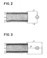
- FIG. 2 represents an embodiment of a device according to the invention.
- layers 3 and 3 ′ of piezoelectric polymer for example polyvinylene fluoride PVF 2 .
- Each of these layers is covered with an electrode 4 and 4 ', connected respectively by connections 5 and 5', to an electric generator delivering a voltage V.
- the electric energy delivered by this electric generator is only supplied to the layers active 3 and 3 '.
- the transformed mechanical energy is greater than in a piezoelectric polymer device of the same thickness, since the capacity of the piezoelectric layers is higher, due to the reduction in thickness.
- a symmetrical structure is adopted which provides the assembly with a stable shape during the effects of thermal expansion.
- layer 6 is made of a conductive polymer.
- Such conductive polymers are generally prepared from an elastomer, in which particles of carbon, or of metals: copper, silver copper, etc. are included.
- the remanent polarizations of the piezoelectric layers 3 and 3 ′ are oriented in the same direction to obtain the most intense traction and compression effects; taking into account that the electric control fields have the same direction. However, by reversing one of the polarizations one can obtain an operation in bending.
- FIG. 3 is a variant of FIG. 2.
- the conductive polymer therefore acts as an electrode for the piezoelectric layers 3 and 3 '.
- the remanent polarizations of the layers 3 and 3 ′ must be in the opposite direction, for traction-compression effects.
- FIG. 4 represents the evolution of the characteristics of a device according to the invention. For flexion operation, it suffices to change the direction of a polarization.
- the gain in relative elongation of a composite film compared to a homogeneous film is represented by the ordinate G of the curve of FIG. 4.
- the magnitude on the abscissa ⁇ represents the ratio of the sum of the thicknesses of the piezoelectric films 3 and 3 ', to the total thickness of the stratified structure.
- the coefficient ⁇ 7 represents the flexibility ratio of the active piezoelectric material composing the layers 3 to 3 ′, to the flexibility of elastic material, composing the layer 1 or 6.
- Figure 4 shows the variation of the gain as a function of the thickness ratio ⁇ , according to certain values of the coefficient ⁇ .
- ⁇ 1
- the gain G is minimal whatever the value of the quantity tP
- An example of a device according to the invention can be produced in the following manner, without limiting.
- the piezoelectric layers are polyvinylidene fluoride PYF 2 deposited on the intermediate polymer by dipping.
- PVF 2 is dissolved in dymethyl formamide DMF in an amount of 100 to 200 g / 1.
- the intermediate polymer film is coated by passage through a tank of PVF 2 + DMF solution.
- the solvent is evaporated at the temperature of 70 to 80 ° C by jets of hot air, or radiation of electrical resistances.
- the low temperature favors the appearance of the non-oriented y phase.
- the film can then be stretched, by a factor of 2 to 3 at 90 - 100 ° C: the phase there is therefore transformed into oriented ⁇ phase; if the composite film is not stretched, its mechanical and piezoelectric properties will be isotropic in its plane.
- the composite film is then metallized on its two faces, using for example the deposition of aluminum under vacuum. It is then polarized between these latter electrodes, by applying an electric field of 0.5 to 1 MV / cm in the PVF 2 layers, at 80 ° C. for a few minutes: the polarization configuration essentially depends on the results that the 'we wish to obtain.
- the voltage generator of Figures 2 and 3 is then replaced by a bias voltage generator.
- the thicknesses of the achievable piezoelectric layers are greater than or equal to 1 ⁇ m. In the case described, using a conductive intermediate polymer, the same polymers can be used, loaded with carbon or metal particles.
- the flexible material has been specially described as a polymer having a low stiffness. It is also possible, without departing from the scope of the invention, to use other extensible materials.
- the invention relates to all the applications of piezoelectric films and transducers, in particular electroacoustic ones such as loudspeakers, headphones, various transmitters.
Landscapes
- Physics & Mathematics (AREA)
- Engineering & Computer Science (AREA)
- Acoustics & Sound (AREA)
- Signal Processing (AREA)
- Piezo-Electric Transducers For Audible Bands (AREA)
Description
L'invention se rapporte à des dispositifs transducteurs utilisant des films de polymères susceptibles de présenter des phénomènes de pié- zoélectricité par application d'un champ de polarisation.The invention relates to transducer devices using polymer films capable of exhibiting piezoelectricity phenomena by application of a polarization field.
Il est connu de réaliser un transducteur électromécanique composé d'une feuille médiane de matière absorbant l'énergie vibratoire, sur les deux faces de laquelle adhèrent des éléments actifs constitués par un film de polymère piézoélectrique métallisé sur ses deux faces. Les métallisations intérieures sont reliées à une première borne et les métallisations extérieures sont reliées à une seconde borne. Une telle structure est mentionnée dans le document DE-A-2803168.It is known to produce an electromechanical transducer composed of a median sheet of material absorbing vibrational energy, on the two faces of which adhere active elements constituted by a film of piezoelectric polymer metallized on its two faces. The interior metallizations are connected to a first terminal and the exterior metallizations are connected to a second terminal. Such a structure is mentioned in document DE-A-2803168.
L'invention s'applique notamment à des structures composées de'fitms polymères piézoélectriques associés à d'autres films polymères, en particulier à une structure comportant au moins une couche de polymère polaire associée à une autre couche de polymère, telle que à épaisseur égale, la réponse mécanique à une tension électrique de commande est accrue par rapport à celle que produirait un film homogène de même polymère polaire.The invention is particularly applicable to structures composed of piezoelectric polymer films associated with other polymer films, in particular to a structure comprising at least one layer of polar polymer associated with another layer of polymer, such as with equal thickness. , the mechanical response to an electrical control voltage is increased compared to that which a homogeneous film of the same polar polymer would produce.
Certains films de polymères polaires tels que le chlorure de polyvinyle (PVC), le polyfluorure de vinyle (PVF), le polyfluorure de vinylidène (PVF2) et certains polymères comme PVF2 - PTFE (polyfluorure de vinylidène - poly- tétrafluorure d'éthylène), sont connus pour présenter des propriétés piézoélectriques, et trouvent leurs applications dans des transducteurs et capteurs électroacoustiques par exemple.Certain films of polar polymers such as polyvinyl chloride (PVC), polyvinyl fluoride (PVF), polyvinylidene fluoride (PVF 2 ) and certain polymers such as PVF 2 - PTFE (polyvinylidene fluoride - polyethylene tetrafluoride) ), are known to have piezoelectric properties, and find their applications in electroacoustic transducers and sensors for example.
D'une façon générale, les propriétés piézoélectriques de ces films sont décrites par une relation tensorielle entre les composantes P; de la polarisation et les composantes Xjk des contraintes mécaniques. On définit alors un tenseur appelé tenseur des coefficients piézoélectriques Dijk. En première approximation, dans le cas d'une polarisation rémanente uniaxiale, un polymère piézoélectrique présente des coefficients piézoélectriques d'autant plus élevés que la valeur de la polarisation remanente est grande, et que sa souplesse mécanique, dans une direction considérée, est plus élevée.In general, the piezoelectric properties of these films are described by a tensorial relationship between the P components; of the polarization and the components X jk of the mechanical stresses. We then define a tensor called the tensor of the piezoelectric coefficients D ijk . As a first approximation, in the case of a uniaxial remanent polarization, a piezoelectric polymer has piezoelectric coefficients that are higher as the value of the remanent polarization is high, and as its mechanical flexibility, in a direction considered, is higher .
Par exemple, dans le cas du polyfluorure de vinylidène, pour une polarisation rémanente de P=6.10-2 Cm-2 perpendiculaire au film d'épaisseur 20 um, on obtient un coefficient piézoélectrique dans une direction parallèle au film de 20 pCN -1 et un allongement relatif dans la même direction du plan du film de 10-6 par volt appliqué. On définit également, par le facteur de couplage électromécanique K, l'effet transducteur électromécanique. Plus précisément, K2 est égal au rapport de l'énergie mécanique transformée par effet piézoélectrique, à l'énergie électrique stockée.For example, in the case of polyvinylidene fluoride, for a remanent polarization of P = 6.10-2 Cm- 2 perpendicular to the film with a thickness of 20 μm, a piezoelectric coefficient is obtained in a direction parallel to the film of 20 pCN -1 and a relative elongation in one direction of the film plane of 10- 6 per volt applied. The electromechanical coupling factor K also defines the electromechanical transducer effect. More precisely, K 2 is equal to the ratio of the mechanical energy transformed by the piezoelectric effect, to the stored electrical energy.
Dans le cas du polyfluorure de vinylidène cité plus haut en exemple, le coefficient de couplage électromécanique vaut : K2=1,2x 10⁻².In the case of polyvinylidene fluoride cited above as an example, the electromechanical coupling coefficient is: K2 = 1.2x 10⁻².
Dans la plupart des applications de transducteurs électroacoustiques, haut parleur, écouteur, émetteur pour sonar ou échographie, la tension d'excitation disponible est limitée, mais non l'intensité.In most applications of electroacoustic transducers, loudspeaker, earphone, transmitter for sonar or ultrasound, the excitation voltage available is limited, but not the intensity.
L'intérêt de l'invention par rapport aux dispositifs existant dans l'art antérieur, réside dans le couplage maximum d'énergie. électrique, à basse tension, pour en tirer le maximum d'énergie mécanique.The advantage of the invention compared to the devices existing in the prior art lies in the maximum energy coupling. electric, low voltage, to get the maximum mechanical energy.
En effet, un dispositif monolithique possède une certaine raideur qui, lors d'une excitation électrique, contrarie les déformations mécaniques et limite donc, par ce fait, les effets piézoélectriques perçus extérieurement. On peut améliorer les résultats en augmentant la valeur de l'énergie électrique cédée au dispositif. Pour un même matériau piézoélectrique, cet effet peut s'effectuer en réduisant l'épaisseur du film piézoélectrique mais dans ce cas, la résistance mécanique du dispositif n'est plus satisfaisante.Indeed, a monolithic device has a certain stiffness which, during an electrical excitation, counteracts the mechanical deformations and therefore limits, by this fact, the piezoelectric effects perceived externally. The results can be improved by increasing the value of the electrical energy given to the device. For the same piezoelectric material, this effect can be achieved by reducing the thickness of the piezoelectric film, but in this case, the mechanical resistance of the device is no longer satisfactory.
Un dispositif conforme à l'invention permet de conserver une bonne résistance mécanique, étant donné que l'épaisseur totale des matériaux est inchangée, d'augmenter notablement les effets piézoélectriques en réduisant l'influence de la raideur inhérente aux couches piézoélectriques utilisées et de délivrer plus d'énergie électrique aux couches actives du dispositif.A device according to the invention makes it possible to maintain good mechanical strength, since the total thickness of the materials is unchanged, to significantly increase the piezoelectric effects by reducing the influence of the stiffness inherent in the piezoelectric layers used and to deliver more electrical energy to the active layers of the device.
La présente demande de brevet concerne une structure comprenant au moins un film piézoélectrique dans lequel l'allongement relatif par volt appliqué, ainsi que l'énergie mécanique fournie par volt appliqué, sont supérieurs à ceux du polymère polaire homogène de même épaisseur.The present patent application relates to a structure comprising at least one piezoelectric film in which the relative elongation per applied volt, as well as the mechanical energy supplied by applied volt, are greater than those of the homogeneous polar polymer of the same thickness.
En conséquence, l'invention a pour objet une structure de transducteur électromécanique composée d'un élément sustentateur passif en- cadé par deux films polymères actifs en matériau piézoélectrique ayant des faces internes qui adhèrent aux faces porteuses dudit élément sustentateur et des faces externes revêtues d'électrodes; une liaison électrique équipotentielle étant établie entre lesdites faces porteuses, caractérisé en ce que lesdites faces porteuses sont les faces d'un film en matériau polymère assurant par conductivité électrique propre ladite liaison électrique équipotentielle; ledit matériau polymère offrant une rigidité mécanique inférieure à celle dudit matériau piézoélectrique.Consequently, the subject of the invention is an electromechanical transducer structure composed of a passive lift element surrounded by two active polymer films made of piezoelectric material having internal faces which adhere to the load-bearing faces of said lift element and external faces coated with 'electrodes; an equipotential electrical connection being established between said load-bearing faces, characterized in that said load-bearing faces are the faces of a film of polymer material ensuring, by own electrical conductivity, said equipotential electrical connection; said polymer material offering a mechanical rigidity lower than that of said piezoelectric material.
L'invention sera mieux comprise à l'aide de la description suivante et des figures annexées parmi lesquelles:
- la figure 1 représente les comportements respectifs d'un dispositif transducteur suivant l'art antérieur et d'un dispositif suivant l'invention;
- la figure 2 représente un mode de réalisation d'un dispositif conforme à l'invention;
- la figure 3 est une variante de la figure 2;
- la figure 4 représente l'évolution des caractéristiques d'un dispositif selon l'invention.
- La figure 1 représente les comportements, lors de sollicitations extérieures électriques, d'un dispositif transducteur suivant l'art antérieur, et d'un dispositif suivant l'invention.
- FIG. 1 represents the respective behaviors of a transducer device according to the prior art and of a device according to the invention;
- Figure 2 shows an embodiment of a device according to the invention;
- Figure 3 is a variant of Figure 2;
- FIG. 4 represents the evolution of the characteristics of a device according to the invention.
- FIG. 1 represents the behaviors, during electrical external stresses, of a transducer device according to the prior art, and of a device according to the invention.
Un dispositif selon l'art antérieur est représenté dans la partie gauche de la figure, celui conforme à l'invention était représenté dans la partie droite.A device according to the prior art is shown in the left part of the figure, that according to the invention was shown in the right part.
Un dispositif, tel qu'il existe dans l'art antérieur est constitué d'un film monolithique de matériau piézoélectrique, par exemple un polymère, tel que le montre la figure 1a. Pour visualiser les effets de déformation mécanique, on imagine une ligne de séparation 14 qui limite deux couches (10 et 11) dans le film.A device, as it exists in the prior art, consists of a monolithic film of piezoelectric material, for example a polymer, as shown in FIG. 1a. To visualize the effects of mechanical deformation, imagine a
Un dispositif conforme à l'invention, qui sera décrit plus précisémment dans la suite de la description, comporte un film sustentateur 1 de matériau souple non piézoélectrique, enserré entre deux films de matériaux piézoélectriques 3 et 3', comme il est indiqué figure 1b. Les films 3 et 3' sont mécaniquement solidaires du film 1.A device according to the invention, which will be described more precisely in the following description, comprises a
Lorsque, par l'intermédiaire d'électrodes appropriées, les couches piézoélectriques travaillent en flexion, comme il est représenté sur la figure 1c par un dispositif de l'art antérieur et sur la figure 1 d par un dispositif selon l'invention, on voit que les différences d'épaisseur globales des films, ainsi que les différences de rigidité au niveau de la séparation des différentes couches, permettent d'obtenir un couple moteur plus important dans le dispositif selon l'invention en supposant que la tension d'excitation soit exclusivement appliquée aux couches 3 et 3'.When, via appropriate electrodes, the piezoelectric layers work in bending, as shown in FIG. 1c by a device of the prior art and in FIG. 1d by a device according to the invention, it is seen that the overall thickness differences of the films, as well as the stiffness differences at the level of the separation of the different layers, make it possible to obtain a greater driving torque in the device according to the invention assuming that the excitation voltage is exclusively applied to
Lors d'un travail en traction compression d'un dispositif selon l'art antérieur, comme il est montré figure le, la raideur du matériau limite les effets mécaniques dûs aux excitations électriques. On peut alors songer à réduire l'épaisseur du film pour augmenter l'énergie électrique cédée, sous des valeurs de tension identique, mais dans ce cas la résistance mécanique devient insuffisante.When working in compression compression of a device according to the prior art, as shown in FIG. The, the stiffness of the material limits the mechanical effects due to electrical excitations. One can then think of reducing the thickness of the film to increase the ceded electrical energy, under identical voltage values, but in this case the mechanical resistance becomes insufficient.
Le même effet sur un dispositif conforme à l'invention est montré figure 1f. L'épaisseur des films piézoélectriques 3 et 3' peut être réduite notablement, car la résistance mécanique globale est renforcée par la présence du film sustentateur 1. L'énergie électrique cédée à ce film sustentateur doit être nulle, ce qui peut se réaliser en métallisant les surfaces de contact entre les couches 1 et 3 et les couches 1 et 3' puis en réunissant électriquement ces métallisations. Outre cette condition, il est prévu que la souplesse mécanique du film sustentateur soit supérieure à celle des polymères piézoélectriques utilisés afin que les allongements engendrés par ceux-ci ne soient pas fortement réduits par la nécessité d'allonger l'élément sustentateur.The same effect on a device according to the invention is shown in Figure 1f. The thickness of the
La figure 2 représente un mode de réalisation d'un dispositif conforme à l'invention.FIG. 2 represents an embodiment of a device according to the invention.
Une couche de matériau souple 6, qui est un polymère, reçoit sur chacune de ses deux faces principales des couches 3 et 3' de polymère piézoélectrique, par exemple le polyfluorure de vi- nylédène PVF2. Chacune de ces couches est re- couverte d'une électrode 4 et 4', reliées respectivement par les connexions 5 et 5', à un générateur électrique délivrant une tension V. L'énergie électrique délivrée par ce générateur électrique est uniquement fournie aux couches actives 3 et 3'. A tension égale, l'énergie mécanique transformée est plus importante que dans un dispositif de polymère piézoélectrique de même épaisseur, puisque la capacité des couches piézoélectriques est plus forte, du fait de la réduction d'épaisseur. Selon un mode de réalisation particulièrement avantageux, on adopte une structure symétrique qui assure à l'ensemble une forme stable lors des effets de dilatation thermique.A layer of
Sur la figure 2, la couche 6 est faite d'un polymère conducteur.In Figure 2,
De tels polymères conducteurs sont préparés en général à partir d'un élastomère, dans lequel sont inclues des particules de carbone, ou de métaux:cuivre, cuivre argenté...Such conductive polymers are generally prepared from an elastomer, in which particles of carbon, or of metals: copper, silver copper, etc. are included.
Il faut noter que dans le cas de la figure 2, les polarisations rémanentes des couches piézoélectriques 3 et 3' sont orientées dans le même sens pour obtenir des effets de traction compression les plus intenses; compte-tenu que les champs électriques de commande sont de même sens. Cependant, en inversant l'une des polarisations on peut obtenir un fonctionnement en flexion.It should be noted that in the case of FIG. 2, the remanent polarizations of the
Le polymère conducteur fait donc office d'électrode pour les couches piézoélectriques 3 et 3'.The conductive polymer therefore acts as an electrode for the
Dans le dispositif de la figure 3, les polarisations remanentes des couches 3 et 3' doivent être de sens contraire, pour des effets de traction-compression.In the device of FIG. 3, the remanent polarizations of the
La figure 4 représente l'évolution des caractéristiques d'un dispositif selon l'invention. Pour un fonctionnement en flexion, il suffit de changer le sens d'une polarisation. Le gain en allongement relatif d'un film composite par rapport à un film homogène est représenté par l'ordonnée G de la courbe de la figure 4. La grandeur en abscisse Φ représente le rapport de la somme des épaisseurs des films piézoélectriques 3 et 3', à l'épais- seurtotale de la structure stratifiée.FIG. 4 represents the evolution of the characteristics of a device according to the invention. For flexion operation, it suffices to change the direction of a polarization. The gain in relative elongation of a composite film compared to a homogeneous film is represented by the ordinate G of the curve of FIG. 4. The magnitude on the abscissa Φ represents the ratio of the sum of the thicknesses of the
Le coefficient <7 représente le rapport de souplesse du matériau actif piézoélectrique composant les couches 3 à 3', à la souplesse de matériau élastique, composant la couche 1 ou 6.The coefficient <7 represents the flexibility ratio of the active piezoelectric material composing the
La figure 4 montre la variation du gain en fonction du rapport des épaisseurs Φ, suivant certaines valeurs du coefficient α. On constate que si a=1, le gain G est minime quelle que soit la valeur de la grandeur tP,Figure 4 shows the variation of the gain as a function of the thickness ratio Φ, according to certain values of the coefficient α. We note that if a = 1, the gain G is minimal whatever the value of the quantity tP,
Les courbes sont difficilement exploitables en pratique pour les différences trop grandes entre souplesses et épaisseurs des matériaux. Elles sont alors indiquées en lignes pointillées dans ces régions.The curves are difficult to use in practice for the too large differences between the flexibility and thickness of the materials. They are then indicated in dotted lines in these regions.
Un exemple de dispositif selon l'invention peut être réalisé de la façon suivante, à titre non limitatif.An example of a device according to the invention can be produced in the following manner, without limiting.
Les couches piézoélectriques sont du polyfluorure de vinylidène PYF2 déposées sur le polymère intermédiaire par trempage. Le PVF2 est mis en solution dans le dyméthyl formamide DMF à raison de 100 à 200 g/1. Le film de polymère intermédiaire est enrobé par passage dans une cuve de solution PVF2+DMF. Le solvant est évaporé à la température de 70 à 80° C par jets d'air chaud, ou rayonnement de résistances électriques. La basse température favorise l'apparition de la phase y non orientée. Le film peut ensuite être étiré, d'un facteur 2 à 3 à 90 - 100°C: la phase y est donc transformée en phase β orientée ; si le film composite n'est pas étiré, ses propriétés mécaniques et piézoélectriques seront isotropes dans son plan. Le film composite est ensuite métallisé sur ses deux faces, en utilisant par exemple le dépôt d'Aluminium sous vide. Il est ensuite polarisé entre ces dernières électrodes, par application d'un champ électrique de 0,5 à 1 MV/cm dans les couches de PVF2, à 80°C pendant quelques minutes: la configuration de polarisation dépend essentiellement des résultats que l'on désire obtenir. Le générateur de tension des figures 2 et 3 est alors remplacé par un générateur de tension de polarisation. Les épaisseurs de couches piézoélectriques réalisables sont supérieures ou égales à 1 µm. Dans le cas décrit, utilisant un polymère intermédiaire conducteur, on peut utiliser les mêmes polymères, chargés en particules de carbone ou de métal.The piezoelectric layers are polyvinylidene fluoride PYF 2 deposited on the intermediate polymer by dipping. PVF 2 is dissolved in dymethyl formamide DMF in an amount of 100 to 200 g / 1. The intermediate polymer film is coated by passage through a tank of PVF 2 + DMF solution. The solvent is evaporated at the temperature of 70 to 80 ° C by jets of hot air, or radiation of electrical resistances. The low temperature favors the appearance of the non-oriented y phase. The film can then be stretched, by a factor of 2 to 3 at 90 - 100 ° C: the phase there is therefore transformed into oriented β phase; if the composite film is not stretched, its mechanical and piezoelectric properties will be isotropic in its plane. The composite film is then metallized on its two faces, using for example the deposition of aluminum under vacuum. It is then polarized between these latter electrodes, by applying an electric field of 0.5 to 1 MV / cm in the PVF 2 layers, at 80 ° C. for a few minutes: the polarization configuration essentially depends on the results that the 'we wish to obtain. The voltage generator of Figures 2 and 3 is then replaced by a bias voltage generator. The thicknesses of the achievable piezoelectric layers are greater than or equal to 1 μm. In the case described, using a conductive intermediate polymer, the same polymers can be used, loaded with carbon or metal particles.
Le matériau souple a été spécialement décrit comme un polymère ayant une faible raideur. On peut également employer sans sortir du cadre de l'invention, d'autres matériaux extensibles.The flexible material has been specially described as a polymer having a low stiffness. It is also possible, without departing from the scope of the invention, to use other extensible materials.
L'invention concerne toutes les applications des films piézoélectriques et des transducteurs, notamment électroacoustiques comme les haut- parleurs, écouteurs, émetteurs divers.The invention relates to all the applications of piezoelectric films and transducers, in particular electroacoustic ones such as loudspeakers, headphones, various transmitters.
Claims (7)
Applications Claiming Priority (2)
| Application Number | Priority Date | Filing Date | Title |
|---|---|---|---|
| FR8100780 | 1981-01-16 | ||
| FR8100780A FR2498406A1 (en) | 1981-01-16 | 1981-01-16 | ELECTROMECHANICAL TRANSDUCER STRUCTURE |
Publications (3)
| Publication Number | Publication Date |
|---|---|
| EP0056549A2 EP0056549A2 (en) | 1982-07-28 |
| EP0056549A3 EP0056549A3 (en) | 1982-08-04 |
| EP0056549B1 true EP0056549B1 (en) | 1985-03-27 |
Family
ID=9254236
Family Applications (1)
| Application Number | Title | Priority Date | Filing Date |
|---|---|---|---|
| EP19810402050 Expired EP0056549B1 (en) | 1981-01-16 | 1981-12-22 | Electromechanical transducer structure |
Country Status (4)
| Country | Link |
|---|---|
| EP (1) | EP0056549B1 (en) |
| JP (1) | JPS57138300A (en) |
| DE (1) | DE3169622D1 (en) |
| FR (1) | FR2498406A1 (en) |
Families Citing this family (3)
| Publication number | Priority date | Publication date | Assignee | Title |
|---|---|---|---|---|
| EP0057982B1 (en) * | 1981-02-06 | 1985-12-11 | EMI Limited | Device sensitive to pressure waves |
| FR2519503B1 (en) * | 1981-12-31 | 1991-09-06 | Thomson Csf | POLYMERIC PIEZOELECTRIC TRANSDUCERS AND MANUFACTURING METHOD |
| US5166573A (en) * | 1989-09-26 | 1992-11-24 | Atochem North America, Inc. | Ultrasonic contact transducer and array |
Family Cites Families (4)
| Publication number | Priority date | Publication date | Assignee | Title |
|---|---|---|---|---|
| US3816774A (en) * | 1972-01-28 | 1974-06-11 | Victor Company Of Japan | Curved piezoelectric elements |
| GB1515287A (en) * | 1974-05-30 | 1978-06-21 | Plessey Co Ltd | Piezoelectric transducers |
| GB1593271A (en) * | 1976-09-21 | 1981-07-15 | Standard Telephones Cables Ltd | Electro-acoustic transducers |
| DE2803168C3 (en) * | 1978-01-25 | 1982-10-21 | Friedemann Dipl.-Ing. Dr. 8069 Jetzendorf Meggl | Electromechanical converter |
-
1981
- 1981-01-16 FR FR8100780A patent/FR2498406A1/en not_active Withdrawn
- 1981-12-22 EP EP19810402050 patent/EP0056549B1/en not_active Expired
- 1981-12-22 DE DE8181402050T patent/DE3169622D1/en not_active Expired
-
1982
- 1982-01-14 JP JP475282A patent/JPS57138300A/en active Pending
Also Published As
| Publication number | Publication date |
|---|---|
| JPS57138300A (en) | 1982-08-26 |
| EP0056549A2 (en) | 1982-07-28 |
| DE3169622D1 (en) | 1985-05-02 |
| FR2498406A1 (en) | 1982-07-23 |
| EP0056549A3 (en) | 1982-08-04 |
Similar Documents
| Publication | Publication Date | Title |
|---|---|---|
| EP0168313B1 (en) | Piezoelectric transducer and pressure sensor using such a transducer | |
| US5153859A (en) | Laminated piezoelectric structure and process of forming the same | |
| US4258260A (en) | Pyroelectric infrared detector | |
| EP0086922B1 (en) | Method of production of piezo-electric polymer transducers | |
| JP3093849B2 (en) | Flexible laminated piezoelectric element | |
| FR2496380A1 (en) | PIEZORESISTIVE DEVICE WITH ELECTRICAL CONTROL | |
| EP3443602B1 (en) | Electricity generator comprising a magnetoelectric converter | |
| FR3029815A1 (en) | PIEZOELECTRIC HYDROPHONE WITH PERFORATIONS AND ANTENNA COMPRISING A PLURALITY OF HYDROPHONES | |
| KR20170058768A (en) | Multilayer polyvinylidene polymer piezoelectril film and the preparing method thereof | |
| FR2556165A1 (en) | MULTI-LAYER POLYMER HYDROPHONE NETWORK | |
| JP2019121687A (en) | Photoelectric conversion element, photo sensor, power generator, and photoelectric conversion method | |
| EP0056549B1 (en) | Electromechanical transducer structure | |
| EP3598512A1 (en) | Pyroelectric detection device with stressed suspended membrane | |
| EP2251919B1 (en) | Organic field-effect transistor | |
| FR2701188A1 (en) | Process for manufacturing a piezoelectric component | |
| FR2836552A1 (en) | Piezoelectric accelerometer has a layer and cell arrangement that overcomes problems resulting from serial or parallel connection and provides high voltage sensitivity, while being unaffected by depolarization | |
| EP3340326B1 (en) | Piezoelectric transformer | |
| FR2965991A1 (en) | ACOUSTIC DEVICE FOR GALVANIC ISOLATION | |
| FR2511571A1 (en) | ELECTROACOUSTIC TRANSDUCER WITH CONDENSER WITH POLARIZED SOLID DIELECTRIC | |
| FR2528235A1 (en) | Thin electromechanical transducer - bonded to elastomeric block to enhance the response to match the output of ceramic transducers | |
| JP6972630B2 (en) | Piezoelectric sensor | |
| WO2025195892A1 (en) | Device for measuring compressive force with adaptable sensitivity | |
| CN1118134C (en) | Piezoelectric resonator | |
| FR3120990A1 (en) | MAGNETO-ELECTRIC CONVERTER AND ELECTRICITY GENERATOR COMPRISING SAID CONVERTER | |
| JP2002058096A (en) | Voice generating body |
Legal Events
| Date | Code | Title | Description |
|---|---|---|---|
| PUAI | Public reference made under article 153(3) epc to a published international application that has entered the european phase |
Free format text: ORIGINAL CODE: 0009012 |
|
| PUAL | Search report despatched |
Free format text: ORIGINAL CODE: 0009013 |
|
| AK | Designated contracting states |
Designated state(s): DE GB NL SE |
|
| AK | Designated contracting states |
Designated state(s): DE GB NL SE |
|
| 17P | Request for examination filed |
Effective date: 19820823 |
|
| GRAA | (expected) grant |
Free format text: ORIGINAL CODE: 0009210 |
|
| AK | Designated contracting states |
Designated state(s): DE GB NL SE |
|
| REF | Corresponds to: |
Ref document number: 3169622 Country of ref document: DE Date of ref document: 19850502 |
|
| PG25 | Lapsed in a contracting state [announced via postgrant information from national office to epo] |
Ref country code: SE Effective date: 19851223 |
|
| PLBE | No opposition filed within time limit |
Free format text: ORIGINAL CODE: 0009261 |
|
| STAA | Information on the status of an ep patent application or granted ep patent |
Free format text: STATUS: NO OPPOSITION FILED WITHIN TIME LIMIT |
|
| 26N | No opposition filed | ||
| PG25 | Lapsed in a contracting state [announced via postgrant information from national office to epo] |
Ref country code: NL Effective date: 19860701 |
|
| GBPC | Gb: european patent ceased through non-payment of renewal fee | ||
| NLV4 | Nl: lapsed or anulled due to non-payment of the annual fee | ||
| PG25 | Lapsed in a contracting state [announced via postgrant information from national office to epo] |
Ref country code: DE Effective date: 19860902 |
|
| PG25 | Lapsed in a contracting state [announced via postgrant information from national office to epo] |
Ref country code: GB Effective date: 19881121 |
|
| EUG | Se: european patent has lapsed |
Ref document number: 81402050.9 Effective date: 19860902 |