EP0056567A1 - Dispositif de gonflage - Google Patents
Dispositif de gonflage Download PDFInfo
- Publication number
- EP0056567A1 EP0056567A1 EP81850245A EP81850245A EP0056567A1 EP 0056567 A1 EP0056567 A1 EP 0056567A1 EP 81850245 A EP81850245 A EP 81850245A EP 81850245 A EP81850245 A EP 81850245A EP 0056567 A1 EP0056567 A1 EP 0056567A1
- Authority
- EP
- European Patent Office
- Prior art keywords
- gas
- duct
- bulb
- housing
- side passages
- Prior art date
- Legal status (The legal status is an assumption and is not a legal conclusion. Google has not performed a legal analysis and makes no representation as to the accuracy of the status listed.)
- Granted
Links
Images
Classifications
-
- B—PERFORMING OPERATIONS; TRANSPORTING
- B60—VEHICLES IN GENERAL
- B60S—SERVICING, CLEANING, REPAIRING, SUPPORTING, LIFTING, OR MANOEUVRING OF VEHICLES, NOT OTHERWISE PROVIDED FOR
- B60S5/00—Servicing, maintaining, repairing, or refitting of vehicles
- B60S5/04—Supplying air for tyre inflation
- B60S5/043—Supplying air for tyre inflation characterised by the inflation control means or the drive of the air pressure system
-
- F—MECHANICAL ENGINEERING; LIGHTING; HEATING; WEAPONS; BLASTING
- F04—POSITIVE - DISPLACEMENT MACHINES FOR LIQUIDS; PUMPS FOR LIQUIDS OR ELASTIC FLUIDS
- F04F—PUMPING OF FLUID BY DIRECT CONTACT OF ANOTHER FLUID OR BY USING INERTIA OF FLUID TO BE PUMPED; SIPHONS
- F04F5/00—Jet pumps, i.e. devices in which flow is induced by pressure drop caused by velocity of another fluid flow
- F04F5/14—Jet pumps, i.e. devices in which flow is induced by pressure drop caused by velocity of another fluid flow the inducing fluid being elastic fluid
- F04F5/16—Jet pumps, i.e. devices in which flow is induced by pressure drop caused by velocity of another fluid flow the inducing fluid being elastic fluid displacing elastic fluids
- F04F5/18—Jet pumps, i.e. devices in which flow is induced by pressure drop caused by velocity of another fluid flow the inducing fluid being elastic fluid displacing elastic fluids for compressing
-
- F—MECHANICAL ENGINEERING; LIGHTING; HEATING; WEAPONS; BLASTING
- F17—STORING OR DISTRIBUTING GASES OR LIQUIDS
- F17C—VESSELS FOR CONTAINING OR STORING COMPRESSED, LIQUEFIED OR SOLIDIFIED GASES; FIXED-CAPACITY GAS-HOLDERS; FILLING VESSELS WITH, OR DISCHARGING FROM VESSELS, COMPRESSED, LIQUEFIED, OR SOLIDIFIED GASES
- F17C5/00—Methods or apparatus for filling containers with liquefied, solidified, or compressed gases under pressures
- F17C5/06—Methods or apparatus for filling containers with liquefied, solidified, or compressed gases under pressures for filling with compressed gases
-
- F—MECHANICAL ENGINEERING; LIGHTING; HEATING; WEAPONS; BLASTING
- F17—STORING OR DISTRIBUTING GASES OR LIQUIDS
- F17C—VESSELS FOR CONTAINING OR STORING COMPRESSED, LIQUEFIED OR SOLIDIFIED GASES; FIXED-CAPACITY GAS-HOLDERS; FILLING VESSELS WITH, OR DISCHARGING FROM VESSELS, COMPRESSED, LIQUEFIED, OR SOLIDIFIED GASES
- F17C2201/00—Vessel construction, in particular geometry, arrangement or size
- F17C2201/01—Shape
- F17C2201/0104—Shape cylindrical
- F17C2201/0109—Shape cylindrical with exteriorly curved end-piece
-
- F—MECHANICAL ENGINEERING; LIGHTING; HEATING; WEAPONS; BLASTING
- F17—STORING OR DISTRIBUTING GASES OR LIQUIDS
- F17C—VESSELS FOR CONTAINING OR STORING COMPRESSED, LIQUEFIED OR SOLIDIFIED GASES; FIXED-CAPACITY GAS-HOLDERS; FILLING VESSELS WITH, OR DISCHARGING FROM VESSELS, COMPRESSED, LIQUEFIED, OR SOLIDIFIED GASES
- F17C2201/00—Vessel construction, in particular geometry, arrangement or size
- F17C2201/05—Size
- F17C2201/058—Size portable (<30 l)
-
- F—MECHANICAL ENGINEERING; LIGHTING; HEATING; WEAPONS; BLASTING
- F17—STORING OR DISTRIBUTING GASES OR LIQUIDS
- F17C—VESSELS FOR CONTAINING OR STORING COMPRESSED, LIQUEFIED OR SOLIDIFIED GASES; FIXED-CAPACITY GAS-HOLDERS; FILLING VESSELS WITH, OR DISCHARGING FROM VESSELS, COMPRESSED, LIQUEFIED, OR SOLIDIFIED GASES
- F17C2205/00—Vessel construction, in particular mounting arrangements, attachments or identifications means
- F17C2205/01—Mounting arrangements
- F17C2205/0103—Exterior arrangements
- F17C2205/0111—Boxes
-
- F—MECHANICAL ENGINEERING; LIGHTING; HEATING; WEAPONS; BLASTING
- F17—STORING OR DISTRIBUTING GASES OR LIQUIDS
- F17C—VESSELS FOR CONTAINING OR STORING COMPRESSED, LIQUEFIED OR SOLIDIFIED GASES; FIXED-CAPACITY GAS-HOLDERS; FILLING VESSELS WITH, OR DISCHARGING FROM VESSELS, COMPRESSED, LIQUEFIED, OR SOLIDIFIED GASES
- F17C2205/00—Vessel construction, in particular mounting arrangements, attachments or identifications means
- F17C2205/03—Fluid connections, filters, valves, closure means or other attachments
- F17C2205/0302—Fittings, valves, filters, or components in connection with the gas storage device
- F17C2205/0323—Valves
- F17C2205/0329—Valves manually actuated
-
- F—MECHANICAL ENGINEERING; LIGHTING; HEATING; WEAPONS; BLASTING
- F17—STORING OR DISTRIBUTING GASES OR LIQUIDS
- F17C—VESSELS FOR CONTAINING OR STORING COMPRESSED, LIQUEFIED OR SOLIDIFIED GASES; FIXED-CAPACITY GAS-HOLDERS; FILLING VESSELS WITH, OR DISCHARGING FROM VESSELS, COMPRESSED, LIQUEFIED, OR SOLIDIFIED GASES
- F17C2205/00—Vessel construction, in particular mounting arrangements, attachments or identifications means
- F17C2205/03—Fluid connections, filters, valves, closure means or other attachments
- F17C2205/0302—Fittings, valves, filters, or components in connection with the gas storage device
- F17C2205/0323—Valves
- F17C2205/0335—Check-valves or non-return valves
-
- F—MECHANICAL ENGINEERING; LIGHTING; HEATING; WEAPONS; BLASTING
- F17—STORING OR DISTRIBUTING GASES OR LIQUIDS
- F17C—VESSELS FOR CONTAINING OR STORING COMPRESSED, LIQUEFIED OR SOLIDIFIED GASES; FIXED-CAPACITY GAS-HOLDERS; FILLING VESSELS WITH, OR DISCHARGING FROM VESSELS, COMPRESSED, LIQUEFIED, OR SOLIDIFIED GASES
- F17C2221/00—Handled fluid, in particular type of fluid
- F17C2221/01—Pure fluids
- F17C2221/013—Carbon dioxide
-
- F—MECHANICAL ENGINEERING; LIGHTING; HEATING; WEAPONS; BLASTING
- F17—STORING OR DISTRIBUTING GASES OR LIQUIDS
- F17C—VESSELS FOR CONTAINING OR STORING COMPRESSED, LIQUEFIED OR SOLIDIFIED GASES; FIXED-CAPACITY GAS-HOLDERS; FILLING VESSELS WITH, OR DISCHARGING FROM VESSELS, COMPRESSED, LIQUEFIED, OR SOLIDIFIED GASES
- F17C2223/00—Handled fluid before transfer, i.e. state of fluid when stored in the vessel or before transfer from the vessel
- F17C2223/01—Handled fluid before transfer, i.e. state of fluid when stored in the vessel or before transfer from the vessel characterised by the phase
- F17C2223/0107—Single phase
- F17C2223/0123—Single phase gaseous, e.g. CNG, GNC
-
- F—MECHANICAL ENGINEERING; LIGHTING; HEATING; WEAPONS; BLASTING
- F17—STORING OR DISTRIBUTING GASES OR LIQUIDS
- F17C—VESSELS FOR CONTAINING OR STORING COMPRESSED, LIQUEFIED OR SOLIDIFIED GASES; FIXED-CAPACITY GAS-HOLDERS; FILLING VESSELS WITH, OR DISCHARGING FROM VESSELS, COMPRESSED, LIQUEFIED, OR SOLIDIFIED GASES
- F17C2223/00—Handled fluid before transfer, i.e. state of fluid when stored in the vessel or before transfer from the vessel
- F17C2223/03—Handled fluid before transfer, i.e. state of fluid when stored in the vessel or before transfer from the vessel characterised by the pressure level
- F17C2223/036—Very high pressure (>80 bar)
-
- F—MECHANICAL ENGINEERING; LIGHTING; HEATING; WEAPONS; BLASTING
- F17—STORING OR DISTRIBUTING GASES OR LIQUIDS
- F17C—VESSELS FOR CONTAINING OR STORING COMPRESSED, LIQUEFIED OR SOLIDIFIED GASES; FIXED-CAPACITY GAS-HOLDERS; FILLING VESSELS WITH, OR DISCHARGING FROM VESSELS, COMPRESSED, LIQUEFIED, OR SOLIDIFIED GASES
- F17C2260/00—Purposes of gas storage and gas handling
- F17C2260/03—Dealing with losses
- F17C2260/035—Dealing with losses of fluid
- F17C2260/036—Avoiding leaks
-
- F—MECHANICAL ENGINEERING; LIGHTING; HEATING; WEAPONS; BLASTING
- F17—STORING OR DISTRIBUTING GASES OR LIQUIDS
- F17C—VESSELS FOR CONTAINING OR STORING COMPRESSED, LIQUEFIED OR SOLIDIFIED GASES; FIXED-CAPACITY GAS-HOLDERS; FILLING VESSELS WITH, OR DISCHARGING FROM VESSELS, COMPRESSED, LIQUEFIED, OR SOLIDIFIED GASES
- F17C2270/00—Applications
- F17C2270/01—Applications for fluid transport or storage
- F17C2270/0165—Applications for fluid transport or storage on the road
- F17C2270/0168—Applications for fluid transport or storage on the road by vehicles
- F17C2270/0178—Cars
-
- F—MECHANICAL ENGINEERING; LIGHTING; HEATING; WEAPONS; BLASTING
- F17—STORING OR DISTRIBUTING GASES OR LIQUIDS
- F17C—VESSELS FOR CONTAINING OR STORING COMPRESSED, LIQUEFIED OR SOLIDIFIED GASES; FIXED-CAPACITY GAS-HOLDERS; FILLING VESSELS WITH, OR DISCHARGING FROM VESSELS, COMPRESSED, LIQUEFIED, OR SOLIDIFIED GASES
- F17C2270/00—Applications
- F17C2270/07—Applications for household use
- F17C2270/0772—Inflation devices, e.g. for rescue vests or tyres
Definitions
- the present invention relates to an inflating device of the kind disclosed in the preamble to the following claim 1.
- the object of the present invention is to provide an inflating device, which is small in size, cheap to manufacture and use, which may even so be made in a single size, if necessary, to cover most of the above-mentioned customarily prevailing applications.
- the inflating device having been given the characterizing features disclosed in claim 1.
- a separate gas container or bulb as a high pressure chamber, suitably an ordinary carbon dioxide bulb, which may be bought almost anywhere, and which may be stored for an unlimited time in its sealed state without losing pressure, a higher pressure may be permitted in the chamber. Should the gas or air quantity remaining in the bulb be found insufficient in some particular case, the used bulb may be removed and a filled spare bulb inserted instead, such a bulb taking up an insignificant amount of space in storage.
- the high pressure in such a cartridge is utilized by forming the discharge duct, in an inflating device in accordance with the invention, as an ejector means with side passages for the induction of secondary air into the discharge duct. For every part by volume of primare gas from the bulb, an addition of about 5 to 20 parts by volume of secondary air may thus be obtained.
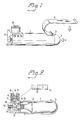
- the embodiment illustrated of the inventive device in Figures 1 and 2 has a housing 1, in which a gas bulb 2 (an ordinary carbon dioxide bulb) is placed. At one end of the housing 1 there is an opening 3, through which the bulb is inserted and which is closed off by a hinged, J-shaped member 4. In the position illustrated in Figure 3, this member 4 retains the bulb 2 in its correct position with its neck 5 thrust into an 0-ring 6, which seals the neck 5 so that the outlet of the bulb is in gas-tight communication with a discharge duct 7 arranged in the housing 1.
- the discharge duct 7 passes through a nozzle 8 having a packing 9, adapted to the valve (not shown) of a bicycle inner tube, for example.
- the discharge duct 7 also includes a constricted portion 10 which, together with side passages 11 to the outside of the housing, and the packing 9 or a valve (not shown) inserted from the outside into the packing fors an ejector means.
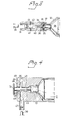
- FIG. 3 functions in principle in the same way as the devi of Figures 1 and 2, but here a discharge nozzle 31 is arran coaxially with a housing 32 and displaceable therein agains the bias of a spring 33.
- a discharge tube 34 is attached to the nozzle 34, and extends through a rubber pad 36 such that a solid, pointed free end 35 of the tube 34 is in register with, and spaced from a sealed end 37 of a gas bul 38, which in this case is not provided with the otherwise customary valve corresponding to the valve 13 of Figure 2.
- a bicycl tire valve 39 it is displaced in the housing such That the sharp end 35 penetrates the sealed end 37 of the bulb and gas can flow into the tube 34 via a slit 40 in the wall thereof, the slit 40 straddling the rubber pad 36 axially at this juncture, thus allowing gas to flow out of the nozzle 31 and to the tire valve 39.
- the discharge passage is here also formed as an ejector for inducting secondary air through side passages 41 provided with non-return valves 42.
- a gas bulb of the same kind as that in Figures 1 and 2 is used, and its valve 13 is operated by a similar push rod 14 as in said Figures.
- a discharge duct 43 is arranged concentrically about the push rod 14 and normal to the end wall 44, where the duct merges into a radially directed, annular slit 45 opening out into an annular duct 46 provided with a radial discharge nozzle 47.
- substantially axial secondary air passages 48 extending through the end wall 44, and provided with non-return flaps 49 on the inside surface of the end wall.
- An ejector means is thus formed in this case as well, where the gas flow reaches the speed of sound on deflection at the end wall 44, and a heavy induction of secondary air via the passages 48 is obtained, whereat up to 20 parts by volume of air for one part by volume of gas flowing from the bulb may be obtained.
Landscapes
- Engineering & Computer Science (AREA)
- Mechanical Engineering (AREA)
- General Engineering & Computer Science (AREA)
- Physics & Mathematics (AREA)
- Fluid Mechanics (AREA)
- Jet Pumps And Other Pumps (AREA)
- Filling Or Discharging Of Gas Storage Vessels (AREA)
- Thin Film Transistor (AREA)
- Heterocyclic Carbon Compounds Containing A Hetero Ring Having Oxygen Or Sulfur (AREA)
- Joints Allowing Movement (AREA)
- Control Of Vending Devices And Auxiliary Devices For Vending Devices (AREA)
- Vehicle Cleaning, Maintenance, Repair, Refitting, And Outriggers (AREA)
Priority Applications (1)
| Application Number | Priority Date | Filing Date | Title |
|---|---|---|---|
| AT81850245T ATE15995T1 (de) | 1981-01-12 | 1981-12-15 | Vorrichtung zum aufblasen. |
Applications Claiming Priority (2)
| Application Number | Priority Date | Filing Date | Title |
|---|---|---|---|
| SE8100129A SE442498B (sv) | 1981-01-12 | 1981-01-12 | Luftpafyllningsanordning |
| SE8100129 | 1981-01-12 |
Publications (2)
| Publication Number | Publication Date |
|---|---|
| EP0056567A1 true EP0056567A1 (fr) | 1982-07-28 |
| EP0056567B1 EP0056567B1 (fr) | 1985-10-09 |
Family
ID=20342855
Family Applications (1)
| Application Number | Title | Priority Date | Filing Date |
|---|---|---|---|
| EP81850245A Expired EP0056567B1 (fr) | 1981-01-12 | 1981-12-15 | Dispositif de gonflage |
Country Status (9)
| Country | Link |
|---|---|
| EP (1) | EP0056567B1 (fr) |
| JP (1) | JPS57151407A (fr) |
| AT (1) | ATE15995T1 (fr) |
| CA (1) | CA1162137A (fr) |
| DE (1) | DE3172639D1 (fr) |
| DK (1) | DK151541C (fr) |
| FI (1) | FI814001A7 (fr) |
| NO (1) | NO820051L (fr) |
| SE (1) | SE442498B (fr) |
Cited By (1)
| Publication number | Priority date | Publication date | Assignee | Title |
|---|---|---|---|---|
| KR100651924B1 (ko) | 2005-07-25 | 2006-12-01 | 주식회사 애니에어 | 비상용 타이어 가스 주입기 |
Citations (5)
| Publication number | Priority date | Publication date | Assignee | Title |
|---|---|---|---|---|
| DE169473C (fr) * | ||||
| US3042290A (en) * | 1960-07-18 | 1962-07-03 | Garrett Corp | Inflation aspirator lock |
| US3370784A (en) * | 1966-02-14 | 1968-02-27 | Ind Covers Inc | Inflation aspirator |
| US4036253A (en) * | 1975-11-12 | 1977-07-19 | Peace Medical | Gas dilution device |
| EP0046275A1 (fr) * | 1980-08-15 | 1982-02-24 | The B.F. GOODRICH Company | Aspirateur pour le gonflage d'articles flexibles |
-
1981
- 1981-01-12 SE SE8100129A patent/SE442498B/sv not_active IP Right Cessation
- 1981-12-14 FI FI814001A patent/FI814001A7/fi not_active Application Discontinuation
- 1981-12-15 EP EP81850245A patent/EP0056567B1/fr not_active Expired
- 1981-12-15 DE DE8181850245T patent/DE3172639D1/de not_active Expired
- 1981-12-15 AT AT81850245T patent/ATE15995T1/de active
- 1981-12-17 CA CA000392529A patent/CA1162137A/fr not_active Expired
-
1982
- 1982-01-08 JP JP57001118A patent/JPS57151407A/ja active Pending
- 1982-01-08 NO NO820051A patent/NO820051L/no unknown
- 1982-01-11 DK DK007382A patent/DK151541C/da not_active IP Right Cessation
Patent Citations (5)
| Publication number | Priority date | Publication date | Assignee | Title |
|---|---|---|---|---|
| DE169473C (fr) * | ||||
| US3042290A (en) * | 1960-07-18 | 1962-07-03 | Garrett Corp | Inflation aspirator lock |
| US3370784A (en) * | 1966-02-14 | 1968-02-27 | Ind Covers Inc | Inflation aspirator |
| US4036253A (en) * | 1975-11-12 | 1977-07-19 | Peace Medical | Gas dilution device |
| EP0046275A1 (fr) * | 1980-08-15 | 1982-02-24 | The B.F. GOODRICH Company | Aspirateur pour le gonflage d'articles flexibles |
Cited By (1)
| Publication number | Priority date | Publication date | Assignee | Title |
|---|---|---|---|---|
| KR100651924B1 (ko) | 2005-07-25 | 2006-12-01 | 주식회사 애니에어 | 비상용 타이어 가스 주입기 |
Also Published As
| Publication number | Publication date |
|---|---|
| NO820051L (no) | 1982-07-13 |
| DK7382A (da) | 1982-07-13 |
| JPS57151407A (en) | 1982-09-18 |
| DE3172639D1 (en) | 1985-11-14 |
| SE442498B (sv) | 1986-01-13 |
| FI814001L (fi) | 1982-07-13 |
| FI814001A7 (fi) | 1982-07-13 |
| ATE15995T1 (de) | 1985-10-15 |
| DK151541B (da) | 1987-12-14 |
| EP0056567B1 (fr) | 1985-10-09 |
| CA1162137A (fr) | 1984-02-14 |
| DK151541C (da) | 1988-08-08 |
| SE8100129L (sv) | 1982-07-13 |
Similar Documents
| Publication | Publication Date | Title |
|---|---|---|
| US2498596A (en) | Tire inflation device | |
| US4004614A (en) | Tether for captive plug of inflation device | |
| US4658869A (en) | Combination tire inflator, gauge and deflator | |
| US10703149B2 (en) | Air valve for tubeless pneumatic tire | |
| US5947172A (en) | Inflator device using a compressed gas cylinder or cartridge | |
| US7051753B1 (en) | Valve for a dunnage bag | |
| US3169665A (en) | Inflating apparatus | |
| US3911988A (en) | Pressurization control device | |
| US3811457A (en) | Over pressurization release device and valve | |
| US4015623A (en) | Tire valve with pressure release means | |
| US4901747A (en) | Tire inflation valve with pressure indicator | |
| US4030644A (en) | Non-return safety valve assembly and pressure pack incorporating same | |
| US5279447A (en) | Fluid dispensing unit with metered outflow | |
| US805474A (en) | Means for inflating rubber tires. | |
| US4015624A (en) | Tire valve | |
| ITBO990157A1 (it) | Pompa ad anidride carbonica per pneumatici . | |
| EP0492333B1 (fr) | Structure de fermeture pour récipients à liquide pulvérisable | |
| CN109307152B (zh) | 具有安全装置的充气接头及其与高压气瓶的组合 | |
| US3692071A (en) | Nozzle for inflating balloons | |
| US3796181A (en) | Help or lost balloon | |
| WO1994015686A1 (fr) | Ballon a cartouche d'approvisionnement en helium associee | |
| US3851588A (en) | Pyrotechnic devices | |
| EP0056567B1 (fr) | Dispositif de gonflage | |
| US5738459A (en) | "Pressurized refill with multiple seal valve core plug and a method for pressurizing a refill" | |
| US3491918A (en) | Aerosol dispenser |
Legal Events
| Date | Code | Title | Description |
|---|---|---|---|
| PUAI | Public reference made under article 153(3) epc to a published international application that has entered the european phase |
Free format text: ORIGINAL CODE: 0009012 |
|
| AK | Designated contracting states |
Designated state(s): AT BE CH DE FR GB IT NL |
|
| 17P | Request for examination filed |
Effective date: 19830119 |
|
| GRAA | (expected) grant |
Free format text: ORIGINAL CODE: 0009210 |
|
| AK | Designated contracting states |
Designated state(s): AT BE CH DE FR GB IT LI NL |
|
| PG25 | Lapsed in a contracting state [announced via postgrant information from national office to epo] |
Ref country code: NL Effective date: 19851009 Ref country code: LI Effective date: 19851009 Ref country code: IT Free format text: LAPSE BECAUSE OF FAILURE TO SUBMIT A TRANSLATION OF THE DESCRIPTION OR TO PAY THE FEE WITHIN THE PRESCRIBED TIME-LIMIT;WARNING: LAPSES OF ITALIAN PATENTS WITH EFFECTIVE DATE BEFORE 2007 MAY HAVE OCCURRED AT ANY TIME BEFORE 2007. THE CORRECT EFFECTIVE DATE MAY BE DIFFERENT FROM THE ONE RECORDED. Effective date: 19851009 Ref country code: CH Effective date: 19851009 Ref country code: BE Effective date: 19851009 Ref country code: AT Effective date: 19851009 |
|
| REF | Corresponds to: |
Ref document number: 15995 Country of ref document: AT Date of ref document: 19851015 Kind code of ref document: T |
|
| ET | Fr: translation filed | ||
| REF | Corresponds to: |
Ref document number: 3172639 Country of ref document: DE Date of ref document: 19851114 |
|
| REG | Reference to a national code |
Ref country code: CH Ref legal event code: PL |
|
| NLV1 | Nl: lapsed or annulled due to failure to fulfill the requirements of art. 29p and 29m of the patents act | ||
| PLBE | No opposition filed within time limit |
Free format text: ORIGINAL CODE: 0009261 |
|
| STAA | Information on the status of an ep patent application or granted ep patent |
Free format text: STATUS: NO OPPOSITION FILED WITHIN TIME LIMIT |
|
| 26N | No opposition filed | ||
| PGFP | Annual fee paid to national office [announced via postgrant information from national office to epo] |
Ref country code: FR Payment date: 19901227 Year of fee payment: 10 |
|
| PGFP | Annual fee paid to national office [announced via postgrant information from national office to epo] |
Ref country code: DE Payment date: 19910116 Year of fee payment: 10 |
|
| PG25 | Lapsed in a contracting state [announced via postgrant information from national office to epo] |
Ref country code: FR Effective date: 19920831 |
|
| PG25 | Lapsed in a contracting state [announced via postgrant information from national office to epo] |
Ref country code: DE Effective date: 19920901 |
|
| REG | Reference to a national code |
Ref country code: FR Ref legal event code: ST |
|
| PGFP | Annual fee paid to national office [announced via postgrant information from national office to epo] |
Ref country code: GB Payment date: 19921209 Year of fee payment: 12 |
|
| PG25 | Lapsed in a contracting state [announced via postgrant information from national office to epo] |
Ref country code: GB Effective date: 19931215 |
|
| GBPC | Gb: european patent ceased through non-payment of renewal fee |
Effective date: 19931215 |