EP0056598B1 - Ski pour ski de fond à appareil de mesure de distance - Google Patents
Ski pour ski de fond à appareil de mesure de distance Download PDFInfo
- Publication number
- EP0056598B1 EP0056598B1 EP82100146A EP82100146A EP0056598B1 EP 0056598 B1 EP0056598 B1 EP 0056598B1 EP 82100146 A EP82100146 A EP 82100146A EP 82100146 A EP82100146 A EP 82100146A EP 0056598 B1 EP0056598 B1 EP 0056598B1
- Authority
- EP
- European Patent Office
- Prior art keywords
- ski
- wheels
- wheel
- digit
- shaft
- Prior art date
- Legal status (The legal status is an assumption and is not a legal conclusion. Google has not performed a legal analysis and makes no representation as to the accuracy of the status listed.)
- Expired
Links
- 239000013013 elastic material Substances 0.000 claims description 3
- 229920002994 synthetic fiber Polymers 0.000 claims 1
- 229920003023 plastic Polymers 0.000 description 3
- 238000004519 manufacturing process Methods 0.000 description 1
- 239000012780 transparent material Substances 0.000 description 1
Images

Classifications
-
- A—HUMAN NECESSITIES
- A63—SPORTS; GAMES; AMUSEMENTS
- A63C—SKATES; SKIS; ROLLER SKATES; DESIGN OR LAYOUT OF COURTS, RINKS OR THE LIKE
- A63C5/00—Skis or snowboards
- A63C5/06—Skis or snowboards with special devices thereon, e.g. steering devices
Definitions
- the invention relates to a ski with a distance meter arranged in the front ski area, the two side wheels arranged on the ski, slightly protruding downward beyond the plane of the ski sole, exposed from the ground, exposed, provided with elastic edge areas and designed as gear wheels has, whose shaft is fixed to the ski.
- the invention has for its object to design the ski mentioned above with a distance meter in such a way that it is suitable as a cross-country ski.
- impellers are arranged in the shovel area of the ski designed as a cross-country ski in such a way that each impeller touches or intersects the tangent that runs through the point of the ski shovel which, when running, is in the usually highest tilt position of the ski has contact with the ground in the rear leg position of the runner.
- the position of the wheels in the specified manner takes into account that the ski is often tilted when running, namely when the cross-country skier has the leg in question at the back.
- the odometer has a plurality of number wheels arranged side by side, one of which rotates one unit each time when the adjacent number wheel makes one revolution, that the shaft of the impellers is identical to the shaft of the number wheels, that a Driving wheel for an extreme number wheel is firmly connected to the shaft, in particular glued, and that the number wheels are loose on the shaft. preferably immediately - surrounded.
- the fact that the impellers and the number wheels sit on the same shaft makes the device simple and small.
- the fact that the number wheels also serve as a reduction also leads to a simplification and the associated smallness of the device.
- an impeller be made of elastic material and that there be a fixed, central circular disc, the diameter of which is preferably less than half the diameter of the impeller. In this way, practically usable wheels are created.
- a housing for the odometer and the running wheels, in particular their elastic parts consist of transparent plastic. This measure apparently makes the device smaller. Another advantage is that the relevant number series is well lit and therefore easy to see.
- an oblique arrow or the like marks the series of numbers indicating the route traveled and is located on the housing.
- the oblique arrow allows the relevant number series to be easily recognized from different angles, even if the distance between the number series and the arrow is arbitrarily in the range of a few millimeters. (A frame around the relevant number series would not be symmetrical to the number series when viewed obliquely.)
- the manufacture of the device is consequently simplified because a small distance between the number series and the arrow that is precisely maintained is not necessary.
- FIG. 1 shows a view of an embodiment of a distance counter according to the invention
- FIG. 2 shows a section along the line 11-11 of FIG. 1
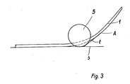
- FIG. 3 shows details relating to the fastening location of the distance counter on the ski.
- With 1 is (are) a ski, with 2 a base plate, with 3 side cheeks, with 4 a U-shaped hood, with 5 running gears made of elastic material, if necessary.
- with a fixed central, disc-shaped insert with 6 number wheels, with 6a a driving wheel, with 7 a marking arrow, designed as a film and glued to the inside of the hood 4, with 8 nuts with closed bottoms, which are glued to the ski, and with 9 Screws, which are supported on the bases of the nuts 8, designated.
- Parts 2-5 are made of transparent material.
- the nuts 8 and the screws 9 are made of light plastic.
- Parts 2-4 are glued together or consist of one piece.
- the number wheels 6 sit loosely on the shaft 10 of the wheels 5 glued to them. They indicate the distance traveled.
- the gearwheels 11 assigned to the number wheels 6 are seated on a shaft 12.
- the driving wheel 6a is seated firmly on the shaft 10.
- the fastening by means of the screws 9 and the nuts 8 allows the device to be removed from the ski: Furthermore, the play between the base plate 2 and the ski 1 and between the screws 9 and the base plate 2 and the fact that the screws 9 and the Nuts 8 are made of plastic, which is somewhat elastic, the shape changes of the ski taken into account during the ride.
- FIG. 1 The location of the distance counter on the ski 1 is shown in FIG. 1.
- the ski When running, the ski is raised slightly in the rear leg position of the runner, the blade area being in further contact with the ground. It is assumed that point A then has contact with the ground.
- the device is now moved into the blade area of the ski from the left until the impeller 5 touches or intersects the tangent t to the blade area of the ski at point A, i.e. H. protrudes somewhat beyond this tangent.
- the wheel 5 must of course also something over the support level s, z. B. 3-4 millimeters protrude. In this position of the impeller 5, it is ensured that it has contact with the ground in all running conditions and that the distance traveled is thus correctly recorded.
Landscapes
- Measurement Of Distances Traversed On The Ground (AREA)
Claims (7)
Priority Applications (1)
| Application Number | Priority Date | Filing Date | Title |
|---|---|---|---|
| AT82100146T ATE6127T1 (de) | 1981-01-13 | 1982-01-11 | Langlaufski mit streckenmesser. |
Applications Claiming Priority (6)
| Application Number | Priority Date | Filing Date | Title |
|---|---|---|---|
| DE3101533 | 1981-01-13 | ||
| DE3101533 | 1981-01-13 | ||
| DE3115122 | 1981-04-10 | ||
| DE19813115122 DE3115122A1 (de) | 1981-01-13 | 1981-04-10 | Ski mit streckenmesser |
| DE3147210 | 1981-11-26 | ||
| DE3147210 | 1981-11-26 |
Publications (3)
| Publication Number | Publication Date |
|---|---|
| EP0056598A2 EP0056598A2 (fr) | 1982-07-28 |
| EP0056598A3 EP0056598A3 (en) | 1983-03-16 |
| EP0056598B1 true EP0056598B1 (fr) | 1984-02-08 |
Family
ID=27189093
Family Applications (1)
| Application Number | Title | Priority Date | Filing Date |
|---|---|---|---|
| EP82100146A Expired EP0056598B1 (fr) | 1981-01-13 | 1982-01-11 | Ski pour ski de fond à appareil de mesure de distance |
Country Status (2)
| Country | Link |
|---|---|
| EP (1) | EP0056598B1 (fr) |
| DE (1) | DE3260039D1 (fr) |
Families Citing this family (3)
| Publication number | Priority date | Publication date | Assignee | Title |
|---|---|---|---|---|
| GB2137363A (en) * | 1983-03-30 | 1984-10-03 | Johnson William N H | Speed indicating device for a ski or the like |
| IT1238714B (it) * | 1990-04-23 | 1993-09-01 | Fazio Massimo Di | Tachimetro-contachilometri per sci da neve e applicazioni similari. |
| FR2809022A1 (fr) * | 2000-05-22 | 2001-11-23 | Arnault Pierre Marie Thullier | Dispositif de mesure de vitesse et de distance pour ski |
Family Cites Families (7)
| Publication number | Priority date | Publication date | Assignee | Title |
|---|---|---|---|---|
| US3505878A (en) * | 1968-03-18 | 1970-04-14 | Edward W Moll | Speed and distance indicator for a ski device |
| DE2236608A1 (de) * | 1972-07-26 | 1974-02-07 | Gerhard Ruehlemann | Wegmessgeraet |
| DE2323499A1 (de) * | 1973-05-10 | 1974-11-21 | Walter Dipl Ing Fuchs | Verfahren und vorrichtung eines tachometers fuer ski-sportgeraete |
| DE2813704C2 (de) * | 1978-03-28 | 1980-07-17 | Jander, Dieter, Dipl.-Ing., 1000 Berlin | Geschwindigkeits -und/oder Strekkenmesser für Ski-Fahrer |
| DE2837834A1 (de) * | 1978-08-28 | 1980-03-13 | Dieter Dipl Ing Jander | Geschwindigkeits- und/oder streckenmesser fuer ski-fahrer |
| DE7935033U1 (de) * | 1979-12-13 | 1980-07-03 | Pataki, Werner, Dipl.-Ing., 7750 Konstanz | Am ski anbringbare, wegabhaengige messvorrichtung |
| DE3040178A1 (de) * | 1980-10-22 | 1982-05-13 | Jander, Dieter, Dipl.-Ing., 1000 Berlin | Geschwindigkeits- und/oder streckenmesser fuer ski-fahrer |
-
1982
- 1982-01-11 DE DE8282100146T patent/DE3260039D1/de not_active Expired
- 1982-01-11 EP EP82100146A patent/EP0056598B1/fr not_active Expired
Also Published As
| Publication number | Publication date |
|---|---|
| EP0056598A3 (en) | 1983-03-16 |
| DE3260039D1 (en) | 1984-03-15 |
| EP0056598A2 (fr) | 1982-07-28 |
Similar Documents
| Publication | Publication Date | Title |
|---|---|---|
| DE4219036A1 (de) | Bindung fuer snowboards | |
| DE2035719C3 (de) | Drehknopf | |
| EP0056598B1 (fr) | Ski pour ski de fond à appareil de mesure de distance | |
| CH643748A5 (de) | Geraet an einem ski zum erfassen der von einem ski-fahrer zurueckgelegten strecke. | |
| DE2819064A1 (de) | Wegstreckenmesser fuer skier | |
| DE3444148A1 (de) | Geldspielautomat mit wenigstens zwei aus gewinnanzeigeelementen zusammengefuegten risikoleitern | |
| DE3816824C3 (de) | Düngerstreuer | |
| DE393786C (de) | Anzeigevorrichtung fuer Signalanzeigeanlagen und Messeinrichtungen mit mehreren Skalen | |
| DE2813704C2 (de) | Geschwindigkeits -und/oder Strekkenmesser für Ski-Fahrer | |
| DE3526028A1 (de) | Anzeigevorrichtung fuer eine uhr | |
| DE3618109C2 (fr) | ||
| DE3735004A1 (de) | Anzeigevorrichtung | |
| AT60530B (de) | Taxmesser, Tourenzähler, Spielzeitkontrollvorrichtung oder dgl. | |
| DE697425C (de) | Vorrichtung zur UEberwachung der Fahrt und der Einstellung elektrisch getriebener Schienenfahrzeuge, insbesondere von Schiebebuehnen | |
| DE702761C (de) | Uhr zur Angabe der Zeit in Bogengraden | |
| DE1478497A1 (de) | Bahnen fuer Spielfahrzeuge | |
| DE3043444A1 (de) | Zifferblatt-anzeigevorrichtung | |
| DE295973C (fr) | ||
| DE404690C (de) | Vorrichtung zur Bestimmung des Brennstoffverbrauchs je Zeiteinheit oder Weg | |
| DE2639322A1 (de) | Uhrvorrichtung fuer lehrzwecke | |
| DE2257114B2 (de) | Geschwindigkeitsmesser | |
| DE951242C (de) | Logarithmische Rechenvorrichtung | |
| DE2247258A1 (de) | Zeitmessgeraet | |
| DE8026032U1 (de) | Heim-roulette-spiel | |
| DE1164816B (de) | Lichtreklamevorrichtung |
Legal Events
| Date | Code | Title | Description |
|---|---|---|---|
| PUAI | Public reference made under article 153(3) epc to a published international application that has entered the european phase |
Free format text: ORIGINAL CODE: 0009012 |
|
| AK | Designated contracting states |
Designated state(s): AT CH DE FR IT |
|
| PUAL | Search report despatched |
Free format text: ORIGINAL CODE: 0009013 |
|
| AK | Designated contracting states |
Designated state(s): AT CH DE FR IT LI |
|
| 17P | Request for examination filed |
Effective date: 19830115 |
|
| ITF | It: translation for a ep patent filed | ||
| GRAA | (expected) grant |
Free format text: ORIGINAL CODE: 0009210 |
|
| AK | Designated contracting states |
Designated state(s): AT CH DE FR IT LI |
|
| REF | Corresponds to: |
Ref document number: 6127 Country of ref document: AT Date of ref document: 19840215 Kind code of ref document: T |
|
| REF | Corresponds to: |
Ref document number: 3260039 Country of ref document: DE Date of ref document: 19840315 |
|
| ET | Fr: translation filed | ||
| PLBE | No opposition filed within time limit |
Free format text: ORIGINAL CODE: 0009261 |
|
| STAA | Information on the status of an ep patent application or granted ep patent |
Free format text: STATUS: NO OPPOSITION FILED WITHIN TIME LIMIT |
|
| PG25 | Lapsed in a contracting state [announced via postgrant information from national office to epo] |
Ref country code: AT Effective date: 19850111 |
|
| PG25 | Lapsed in a contracting state [announced via postgrant information from national office to epo] |
Ref country code: LI Effective date: 19850131 Ref country code: CH Effective date: 19850131 |
|
| 26N | No opposition filed | ||
| PG25 | Lapsed in a contracting state [announced via postgrant information from national office to epo] |
Ref country code: FR Free format text: LAPSE BECAUSE OF NON-PAYMENT OF DUE FEES Effective date: 19850930 |
|
| REG | Reference to a national code |
Ref country code: CH Ref legal event code: PL |
|
| PG25 | Lapsed in a contracting state [announced via postgrant information from national office to epo] |
Ref country code: DE Effective date: 19851001 |
|
| REG | Reference to a national code |
Ref country code: FR Ref legal event code: ST |