EP0056663A2 - Dispositif d'extraction de l'énergie subaquatique - Google Patents
Dispositif d'extraction de l'énergie subaquatique Download PDFInfo
- Publication number
- EP0056663A2 EP0056663A2 EP82101740A EP82101740A EP0056663A2 EP 0056663 A2 EP0056663 A2 EP 0056663A2 EP 82101740 A EP82101740 A EP 82101740A EP 82101740 A EP82101740 A EP 82101740A EP 0056663 A2 EP0056663 A2 EP 0056663A2
- Authority
- EP
- European Patent Office
- Prior art keywords
- impellers
- impeller
- water
- water movement
- working members
- Prior art date
- Legal status (The legal status is an assumption and is not a legal conclusion. Google has not performed a legal analysis and makes no representation as to the accuracy of the status listed.)
- Ceased
Links
- 230000033001 locomotion Effects 0.000 claims abstract description 106
- 238000006243 chemical reaction Methods 0.000 claims abstract description 35
- 238000000034 method Methods 0.000 claims abstract description 9
- XLYOFNOQVPJJNP-UHFFFAOYSA-N water Substances O XLYOFNOQVPJJNP-UHFFFAOYSA-N 0.000 claims description 157
- 230000006870 function Effects 0.000 claims description 29
- 230000004044 response Effects 0.000 claims description 21
- 239000012530 fluid Substances 0.000 claims description 12
- 230000007935 neutral effect Effects 0.000 claims description 12
- 239000002131 composite material Substances 0.000 claims description 7
- 230000000295 complement effect Effects 0.000 claims description 6
- 230000001419 dependent effect Effects 0.000 claims 4
- 230000004043 responsiveness Effects 0.000 claims 4
- 230000008878 coupling Effects 0.000 claims 3
- 238000010168 coupling process Methods 0.000 claims 3
- 238000005859 coupling reaction Methods 0.000 claims 3
- 230000003993 interaction Effects 0.000 claims 3
- 230000000750 progressive effect Effects 0.000 abstract description 16
- 230000005540 biological transmission Effects 0.000 abstract description 9
- 238000012545 processing Methods 0.000 abstract description 2
- 230000025508 response to water Effects 0.000 abstract 1
- 230000000875 corresponding effect Effects 0.000 description 33
- 230000003534 oscillatory effect Effects 0.000 description 27
- 238000005086 pumping Methods 0.000 description 14
- 239000006096 absorbing agent Substances 0.000 description 11
- 230000009471 action Effects 0.000 description 11
- 238000013461 design Methods 0.000 description 9
- 238000009826 distribution Methods 0.000 description 6
- 238000005304 joining Methods 0.000 description 5
- 239000002245 particle Substances 0.000 description 5
- 241000277284 Salvelinus fontinalis Species 0.000 description 4
- 210000000748 cardiovascular system Anatomy 0.000 description 4
- 239000004020 conductor Substances 0.000 description 4
- 238000005516 engineering process Methods 0.000 description 4
- 230000001133 acceleration Effects 0.000 description 3
- 230000008901 benefit Effects 0.000 description 3
- 238000000280 densification Methods 0.000 description 3
- 238000011161 development Methods 0.000 description 3
- 230000000694 effects Effects 0.000 description 3
- 238000000605 extraction Methods 0.000 description 3
- 230000005484 gravity Effects 0.000 description 3
- 230000003595 spectral effect Effects 0.000 description 3
- 238000009825 accumulation Methods 0.000 description 2
- 238000013459 approach Methods 0.000 description 2
- 238000004891 communication Methods 0.000 description 2
- 230000001276 controlling effect Effects 0.000 description 2
- 230000002079 cooperative effect Effects 0.000 description 2
- 230000003247 decreasing effect Effects 0.000 description 2
- 238000006073 displacement reaction Methods 0.000 description 2
- 230000009977 dual effect Effects 0.000 description 2
- 238000007667 floating Methods 0.000 description 2
- 230000004907 flux Effects 0.000 description 2
- 238000012423 maintenance Methods 0.000 description 2
- 230000009467 reduction Effects 0.000 description 2
- 230000009897 systematic effect Effects 0.000 description 2
- 230000003321 amplification Effects 0.000 description 1
- 238000004458 analytical method Methods 0.000 description 1
- 238000003491 array Methods 0.000 description 1
- 238000005266 casting Methods 0.000 description 1
- 230000002860 competitive effect Effects 0.000 description 1
- 230000002596 correlated effect Effects 0.000 description 1
- 238000013016 damping Methods 0.000 description 1
- 238000010612 desalination reaction Methods 0.000 description 1
- 238000005868 electrolysis reaction Methods 0.000 description 1
- 238000004146 energy storage Methods 0.000 description 1
- 230000006872 improvement Effects 0.000 description 1
- 238000009533 lab test Methods 0.000 description 1
- 238000012986 modification Methods 0.000 description 1
- 230000004048 modification Effects 0.000 description 1
- 238000003199 nucleic acid amplification method Methods 0.000 description 1
- 230000010355 oscillation Effects 0.000 description 1
- 230000008569 process Effects 0.000 description 1
- 230000001105 regulatory effect Effects 0.000 description 1
- 230000003014 reinforcing effect Effects 0.000 description 1
- 230000008439 repair process Effects 0.000 description 1
- 238000012552 review Methods 0.000 description 1
- 239000013535 sea water Substances 0.000 description 1
- 238000012360 testing method Methods 0.000 description 1
Images


Classifications
-
- F—MECHANICAL ENGINEERING; LIGHTING; HEATING; WEAPONS; BLASTING
- F03—MACHINES OR ENGINES FOR LIQUIDS; WIND, SPRING, OR WEIGHT MOTORS; PRODUCING MECHANICAL POWER OR A REACTIVE PROPULSIVE THRUST, NOT OTHERWISE PROVIDED FOR
- F03B—MACHINES OR ENGINES FOR LIQUIDS
- F03B13/00—Adaptations of machines or engines for special use; Combinations of machines or engines with driving or driven apparatus; Power stations or aggregates
- F03B13/12—Adaptations of machines or engines for special use; Combinations of machines or engines with driving or driven apparatus; Power stations or aggregates characterised by using wave or tide energy
- F03B13/14—Adaptations of machines or engines for special use; Combinations of machines or engines with driving or driven apparatus; Power stations or aggregates characterised by using wave or tide energy using wave energy
- F03B13/16—Adaptations of machines or engines for special use; Combinations of machines or engines with driving or driven apparatus; Power stations or aggregates characterised by using wave or tide energy using wave energy using the relative movement between a wave-operated member, i.e. a "wom" and another member, i.e. a reaction member or "rem"
- F03B13/18—Adaptations of machines or engines for special use; Combinations of machines or engines with driving or driven apparatus; Power stations or aggregates characterised by using wave or tide energy using wave energy using the relative movement between a wave-operated member, i.e. a "wom" and another member, i.e. a reaction member or "rem" where the other member, i.e. rem is fixed, at least at one point, with respect to the sea bed or shore
- F03B13/1805—Adaptations of machines or engines for special use; Combinations of machines or engines with driving or driven apparatus; Power stations or aggregates characterised by using wave or tide energy using wave energy using the relative movement between a wave-operated member, i.e. a "wom" and another member, i.e. a reaction member or "rem" where the other member, i.e. rem is fixed, at least at one point, with respect to the sea bed or shore and the wom is hinged to the rem
- F03B13/1825—Adaptations of machines or engines for special use; Combinations of machines or engines with driving or driven apparatus; Power stations or aggregates characterised by using wave or tide energy using wave energy using the relative movement between a wave-operated member, i.e. a "wom" and another member, i.e. a reaction member or "rem" where the other member, i.e. rem is fixed, at least at one point, with respect to the sea bed or shore and the wom is hinged to the rem for 360° rotation
- F03B13/183—Adaptations of machines or engines for special use; Combinations of machines or engines with driving or driven apparatus; Power stations or aggregates characterised by using wave or tide energy using wave energy using the relative movement between a wave-operated member, i.e. a "wom" and another member, i.e. a reaction member or "rem" where the other member, i.e. rem is fixed, at least at one point, with respect to the sea bed or shore and the wom is hinged to the rem for 360° rotation of a turbine-like wom
-
- Y—GENERAL TAGGING OF NEW TECHNOLOGICAL DEVELOPMENTS; GENERAL TAGGING OF CROSS-SECTIONAL TECHNOLOGIES SPANNING OVER SEVERAL SECTIONS OF THE IPC; TECHNICAL SUBJECTS COVERED BY FORMER USPC CROSS-REFERENCE ART COLLECTIONS [XRACs] AND DIGESTS
- Y02—TECHNOLOGIES OR APPLICATIONS FOR MITIGATION OR ADAPTATION AGAINST CLIMATE CHANGE
- Y02E—REDUCTION OF GREENHOUSE GAS [GHG] EMISSIONS, RELATED TO ENERGY GENERATION, TRANSMISSION OR DISTRIBUTION
- Y02E10/00—Energy generation through renewable energy sources
- Y02E10/30—Energy from the sea, e.g. using wave energy or salinity gradient
Definitions
- This invention relates in general to means for and methods of extracting energy in usable form from subsurface wave action in a large body of water such as an ocean, and more particularly to a method of and system for producing this result on an arbitrarily large scale, wherein a fundamentally and wholly novel class of wave energy removing impellers responsive to subsurface water movement is made to function cooperatively as an impeller array of novel annular geometry, energetically coupled through an intermediate wave energy conversion and conveyance subsystem of corresponding annular geometry to a centralized means for performing useful work.
- the present invention is best embodied in the form of an overall system for extracting subsurface wave energy, capable of operating at sea on an arbitrarily large scale of wave power output, in any one of a broad range of sea states, and at any depth up to 200 feet 60 (metres) or more, adjustable according to the sea state.
- One general object of this invention is to provide new and improved means for and methods of converting to usable form the subsurface wave energy available within a certain predetermined annular region spanned by the said overall system.
- Another general object of this invention is to enable the efficient, expeditious, economical, and safe operation of the said overall system.
- the conversion to usable form of the said subsurface wave energy is effected by means of a seagoing system that includes an inboard platform or hull, an attached outboard platform or outrigger, and a subsystem of submerged wave energy-removing impellers supported upon the outrigger.
- the hull which may be of circular, oval, or other suitable horizontal cross sectional shape, is completely enclosed by the impeller subsystem and supporting outrigger, which together span an immediately surrounding subsurface region, or volume of water, of corresponding generally annular horizontal cross sectional shape, with maximum horizontal dimensions at least of the same order of magnitude as the typical wavelength L of the ambient natural wave motions, and with maximum vertical dimensions whose magnitude is approximately one-tenth of the said typical wavelength L.
- an optimal combination of functional roles is achieved for each component impeller, of whatever kind and size, by assigning to each of one or more different kinds of component working members of the said impeller, for given fixed values of any preselected combination of its external design parameters, a suitable degree of positive, negative, or neutral buoyancy, together with a suitable combination of values of two distinct kinds of additional internal design parameters.
- the combined wave energy removing action of the said impeller subsystem taking place throughout the aforesaid annular region surrounding the central hull, is complemented by the cooperative action of an intermediate wave energy conversion and conveyance subsystem of corresponding annular geometry, whose function is to transmit in some usable form such as a pressure differential all wave energy extracted throughout the said annular region, to a final centralized wave energy collection subsystem located within the said central hull, and capable of performing useful work.
- the ocean or other large body of water which surrounds the overall seagoing system may be loosely compared to an infinite reservoir of heat energy, whose temperature loosely represents the prevailing sea state.
- the aforesaid final centralized wave energy collection subsystem, located at the center of this overall seagoing system, may be loosely compared to a central heat energy sink, maintained at a constant temperature substantially lower than that of the surrounding infinite heat energy source.
- the just mentioned dual combination of mutually complementary subsystems--the impeller subsystem and the intermediate wave energy conversion and conveyance subsystem-- may then be loosely compared to an interposed heat conductor of suitable annular shape, the exterior boundary of which abuts on the surrounding infinite heat energy source, and the interior boundary of which abuts on the central heat energy sink.
- the overall operating speed of this latter combination of two subsystems may thus be loosely compared to the total rate of inflow of heat through the said annular heat conductor, the overall power conversion efficiency of this dual combination of subsystems being roughly comparable to the thermal conductivity of the said heat conductor.
- the previously mentioned wave frequency spectral function which quantitatively describes in statistical terms the orderly and progressive inward attenuation of the state of the sea that has been mentioned earlier as taking place throughout the said annular region, may be loosely compared to the steady state temperature distribution throughout the said annular heat conductor.
- the present invention achieves, overall, a very broad band range of response over wave amplitude and frequency. But in so doing, the present invention, unlike the Scripps and Salter proposals, completely avoids the further serious disadvantage that is inherent in all wave energy extracting devices which, in order that they might have a broad band response, are made nonresonant at the cost of failing to exploit the resonance phenomenon as a means of wave power amplification.
- the contemplated overall wave energy extraction system is regarded as being composed of various subsystems, classifiable according to their different functions: a seagoing platform subsystem; a platform-supported wave energy removing impeller subsystem of generally annular geometry; an intermediate wave energy conversion and conveyance subsystem of corresponding annular geometry, here embodied as a pressure transmission subsystem; and a final centralized wave energy collection subsystem capable of performing useful work.
- numeral 1 designates generally the complete platform subsystem, which consists of two distinct but securely interconnected sub-subsystems: an inboard platform or hull designated generally by the numeral 2, and a completely surrounding outboard platform or outrigger designated generally by the numeral 3.
- the hull 2 comprises two principal parts: a buoyant, generally doughnut-shaped exterior vessel 4; and a central chamber-defining structure 6 interior thereto.
- the chamber 6 is shown as being domed ( Figure 2), at 8, and as extending downwardly below the bottom of the vessel 4 to define a very large vertical conduit 10.
- the conduit 10 is open at the bottom under normal operating conditions so that ambient water may communicate with the chamber 6 via the conduit 10, the degree of such communication being regulated or, if necessary, annulled by means of a suitable sluice gate 9, as shown schematically in FIG. 2.
- the direction of water flow through conduit 10 is upwards during operation of the overall system.
- alternative embodiments of the present invention are also contemplated wherein the direction of such water flow is, instead, downwards.
- such water flow actuates a turbine device 12 whose runner is suitably adapted to the chosen sense of water flow and is mounted so as to drive any suitable power generating apparatus (not shown) within the shell 14.
- the apparatus may be in the form of an electrical generator, and/or other energy conversion means.
- the shell 14 is mounted centrally within the conduit 10 by means of streamlined struts 16, and is itself streamlined sufficiently to permit water to flow freely therepast in conduit 10.
- the innermost components of the generally annular pressure transmission subsystem are a set of conduits 18, each of which communicates at its inner end with the chamber 6 through a corresponding orifice 22, and extends radially outwardly from the chamber 6.
- Each conduit 18 passes through and beyond the cylindrical outer surface of the vessel 4, and communicates at its outer end, via three parallel vertical extensions 13, 15 and 17, with three corresponding radial ducts 20, approximately midway between the closed inner ends 19 and the closed outer ends 21 of the radial ducts 20.
- FIG. 1 only a few of the conduits 18 and ducts 20 are shown, but it is to be understood that those illustrated are reproduced at the indicated intervals around the entire periphery of the hull 2.
- all of the radial ducts 20 constitute a further set of components of the generally annular pressure transmission subsystem,in communication with the chamber 6 via the conduits 18.
- the interface between the generally annular pressure transmission subsystem and the generally annular impeller subsystem is composed of impeller driven pumps which can act as sources of either relatively positive or relatively negative pressure to be transmitted radially inwardly to chamber 6 via the ducts 20 and conduits 18.
- the impeller driven pumps act as sources of relatively negative pressure
- water is withdrawn by these pumps from the ducts 20, rather than forced into them.
- the turbine device 12 is driven by an inflow of deep-lying ambient water directed upwardly through the conduit 10 to the chamber 6, then directed radially outwardly through conduits 18 to ducts 20, and finally, after withdrawal therefrom by the impeller driven pumps, discharged by the latter to outlying ambient subsurface surroundings.
- the hull 2 and the outrigger 3 form a single, integral, structurally sound, seaworthy overall platform subsystem 1 of adjustable overall buoyancy, capable of floating freely and always practically horizontally on the surface 5 of a large body of water such as an ocean, r at any desired subsurface depth up to 200 feet (60 metres) or more.
- the combined platform subsystem 1 is provided with means of self-propulsion (not shown) from one location at sea to another, from one operating depth to another, and from one operating direction to another.
- Subsystem 1 is further provided with means (not shown) for being moored or otherwise secured to the seabed during periods of inshore operation for maintenance, repairs, and/or the delivery of its stored energy (and processed products, if any) to distribution centers onshore.
- the hull 2 is intended to house all personnel (if not unmanned), as well as features and facilities (most of which are not shown in the drawings) such as: the central turbogenerator, and/or other energy conversion means; an energy storage means; ballast tanks for fine adjustment of overall buoyancy of the overall platform subsystem 1; and seawater electrolysis, desalination, and/or other processing means.
- the dimensions of hull 2 are intended to be sufficiently large for it to accommodate all of the foregoing features and facilities, together with ready means (not all shown) of access thereto at all times by personnel.
- the maximum wave power output of hull 2 might exceed 50 megawatts, its displacement might exceed 50,000 tons, and its draft when floating on the water surface 5 might exceed 100 feet (30 metres).
- the water level 7 in chamber 6 Prior to operation of the overall system as contemplated in this particular embodiment, the water level 7 in chamber 6 must be adjusted to a setting above the orifices 22 of the various conduits 18 by evacuating the air space within the dome 8 as completely as possible; and the interiors of all conduits 18 and of all ducts 20 must be completely filled with water. Moreover, these conditions must be maintained unchanged throughout the subsequent operation of the overall system so as to insure the maintenance, at all times, of a substantial and nearly constant head of water across the turbine device 12. As the state of the sea changes, the foregoing conditions can be maintained unchanged by suitably adjusting the sluice gate 9 to regulate the inflow of water into the conduit 10.
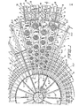
- FIG. 1 Shown schematically in FIG. 1, and in greater detail in FIGS. 3 and 4, are the following spatial and/or functional interrelationships between certain structural parts of the outrigger 3, the pressure transmission subsystem, and the impeller subsystem: (i) midway between every successive pair of radial ducts 20, there is located a radial pipe 24, whose closed inner end is secured to the vessel 4; (ii) laterally supporting and communicating with every radial duct 20, and also joining and communicating with every radial pipe 24, there is located a concentric series of circumferential pipes 26; (iii) through every junction point between radial pipes 24 and circumferential pipes 26, there passes an imaginary vertical axis defining the equilibrium position of a corresponding conical impeller 28 or 30; and (iv) the.impellers 28 and 30, which are of positive and negative overall buoyancy, respectively, are arranged in mutually nested alternation with one another, in the closest order practicable, both radially and circumferentially.
- a skeletonized 2-dimensional annular structure which constitutes the uppermost level of the outrigger 3, comprising and defined by the mutually intersecting and mutually intercommunicating radial pipes 24 and circumferential pipes 26, and supporting as well as communicating with all radial ducts 20.
- a second skeletonized 2-dimensional annular structure which constitutes the lowermost level of the outrigger 3, similarly comprising and defined by an equal number of additional mutually intersecting and mutually intercommunicating circumferential pipes 27 and radial pipes 25, whose closed inner ends are secured to the vessel 4.
- the 3-dimensional structure of the outrigger 3 is essentially completed by a set of vertical pipes 29, each of which is partitioned off into noncommunicating upper and lower sections by a plug 31, each upper section joining and communicating with a corresponding radial pipe 24 and circumferential pipe 26 at their junction point, and each lower section joining and communicating with a corresponding radial pipe 25 and circumferential pipe 27 at their junction point.
- the total number of vertical pipes 29 is equal to the total number of junction points between radial pipes 24 and circumferential pipes 26.
- FIGS. 1 and 2 there is shown schematically one of several identical trusses 23 whose purpose is to provide structural support for outlying parts of the outrigger 3, as well as to enclose and support a corresponding conduit 18.
- the inner ends of each truss 23 are secured to the vessel 4, and the outer ends are secured to the bottom face of a corresponding auxiliary truss 33 in the form of a truncated pyramid with four lateral edges, the base of which is rigidly attached to the lowermost level of the outrigger 3 at four corresponding junction points between radial pipes 25 and circumferential pipes 27, in the manner shown in FIGS. 1 and 2.
- the outrigger 3 thus appears, in FIGS. 1 and 2, as a kind of wheel completely surrounding and securely attached to the vessel 4, the wheel itself being comprised mainly of a securely connected assemblage of nonbuoyant, completely submersed, skeletonized or structurally generally open, rigid 3-dimensional component frameworks (which are not distinguished one from another in the drawings), to which all component impellers are securely linked at appropriately distributed subsurface working locations.
- each two of the said component frameworks that are mutually adjacent are normally interconnected at their common interface in a rigid manner, when the wave induced stresses acting at that interface become too severe the rigid means of interconnection becomes temporarily replaced by a suitable articulation means (not shown in the drawings) for relieving such stresses.
- excessive wave induced stresses acting at the common interfaces between the vessel 4 and the outrigger 3, between the vessel 4 and the trusses 23, and between the trusses 23 and 33 are relieved by the use of such articulation means.
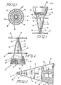
- FIG. 3 Shown in some detail in FIG. 3 are two adjacent impellers 28 and 30, both located on the line 3-3 of FIG. 1. Both of these impellers 28 and 30 have the equilibrium orientation and symmetrical shape (as viewed without regard to their respective composite internal structures) of a vertically oriented cone of revolution whose vertex is its only point of support. Both kinds of impeller 28 and 30 function during normal operation approximately as simple pendulums, capable of oscillating in any vertical plane about their respective positions of stable equilibrium, within the respective limits defined by pipes 24 and 26 in the case of the impeller 28 (see FIG. 5), and by pipes 25 and 27 in the case of the impeller 30. For the impeller 28, whose overall buoyancy is positive, the position of stable equilibrium is vertically above its point of support 32.
- the points of support 32 and 34 are to be understood as being universal pivots, illustrated in FIG. 3 as ball and socket joints 32 and 34 surrounding, respectively, the bottom of the vertical pipe 29 shown on the left, and the top of the vertical pipe 29 shown on the right.
- struts 36 Extending upward from the ball joint 32 supporting the impeller 28 are four struts 36 (see FIGS. 3 and 5); and extending downward from the ball joint 34 supporting the impeller 30 are four similar and similarly placed struts 36.
- the four struts 36 serve in general as a means of rigid support for an assemblage of one or more rigidly interconnected component working members, each of which reacts in a very specific and distinctive way to ambient subsurface water movement.
- the four struts 36 are assumed to be rigidly supporting only one working member in the case of each of the impellers 28 and 30.
- FIGS. 1 the four struts 36 are assumed to be rigidly supporting only one working member in the case of each of the impellers 28 and 30.
- the four struts 36 are assumed to be rigidly supporting an assemblage of two rigidly interconnected component working members in the case of each of the impellers 28 and 30. Whatever may be the number of rigidly interconnected component working members that are supported by the four struts 36, whether for the impeller 28 or for the impeller 30, the entire assemblage of rigidly interconnected component working members will generally have the same gross external geometry (as viewed without regard to its possible internal structure), namely, that of a frustum, with specified altitude, of a cone of revolution having the overall dimensions of the said impellers 28 and 30.
- component working member for the sake of simplicity of illustration, specific examples are shown of only two limiting kinds of component working member: namely, (i) a component working member, generally identified as to its kind by the numeral 38, whose completely enclosing surface possesses the minimum.possible water movement responsive area consistent with its gross external geometry, and whose water movement effective volume-to-surface area ratio is accordingly the maximum possible; and (ii) a component working member, generally identified as to its kind by the numeral 40, whose completely enclosing surface is given an internally multiply reentrant structure such that it thereby acquires the maximum possible water movement responsive area consistent with its gross external geometry, and whose water movement effective volume-to-surface area ratio is accordingly the minimum possible.
- the typical working member 38 is essentially devoid of internal structure. It is buoyant by virtue of being either hollow or otherwise of very low density; and, because of its aforesaid maximal volume-to-surface area ratio, it is maximally responsive to water movement inertial forces and only minimally responsive to water movement drag forces.
- the typical working member 40 possesses considerable internal structure through comprising, in the form illustrated here, a multiplicity of radiating vanes 35.
- Each vane 35 is rigidly attached at its inner edge to a central post 37 ( Figure 6), and is also rigidly attached at its two outer corners to upper and lower rigid circular bands 39 and 41, respectively, both of which are rigidly supported, in turn, by four struts 36.
- the typical working member 40 because of its aforesaid minimal volume-to-surface area ratio, must be, for structural reasons, of very high density, and therefore nonbuoyant. Again, because of its minimal volume-to-surface area ratio, member 40 is maximally responsive to water movement drag forces and only minimally responsive to water movement inertial forces.
- both the operating depths and the dimensions of the impellers 28 and 30 increase with increasing distance measured outwardly from the vessel 4.
- the significance of this feature of the present invention when implemented in combination with the above indicated opportunitites for optimal choice of component working members for the individual impellers 28 and 30, and in combination with the previously mentioned mutually nested and closely ordered arrangement of these individual impellers throughout the annular region spanned by the outrigger 3, is discussed in detail elsewhere in this disclosure.
- This latter subsystem which resembles a cardiovascular system in certain respects, may be conveniently viewed as comprising two distinct parts: a low pressure "venous” part, and a high pressure “arterial” part.
- the "venous” part includes the central chamber 6, the conduits 18 and their extensions 13, 15 and 17, the radial ducts 20, the upper sections of the vertical pipes 29, and the radial pipes 24 and circumferential pipes 26.
- the "arterial” part includes the lower sections of the pipes 29, the radial pipes 25 and circumferential pipes 27, outlets 42 and 44 that discharge water from the respective pipes 25 and 27 to the ambient subsurface surroundings, and, finally, the entire body of water surrounding the overall system.
- the impeller driven pumps all operating independently but in concert, produce throughout the "venous" part of this "cardiovascular system” a substantial, net reduction of pressure relative to that of the "arterial” part.
- a very important advantage is gained through the novel annular geometry and the resulting spatial and functional economy of the present pressure transmission subsystem.
- Each of the impeller driven pumps may be any suitable pumping device mechanically coupled respectively to the fixed vertical pipes 29 and the moving struts 36 to effect pumping of water from the upper to the lower sections of the vertical pipes 29 (which, it will be recalled, are separated by plugs 31). Since a multitude of different pump designs may be employed and readily adapted by those skilled in the art, the type of pumping device is not shown in any detail in the drawings. Instead, a conical "box,” labeled by the numeral 46, is used in the drawings to illustrate each individual impeller driven pumping device.
- FIGS. 1 and 2 there is shown mounted on the outrigger 3, outwardly of the radial rows of impellers 28 and 30, a further circumferential series of impellers 50, all of overall neutral buoyancy and all identical.
- Each of these impellers 50 functions during normal operation approximately as a simple pendulum, capable of oscillating only about a horizontal axis of support 48.
- Every such impeller 50 has the equilibrium position and symmetrical shape (as viewed without regard to its internal structure) of a right prism whose bases are isosceles triangles, whose two congruent rectangular lateral faces meet in a corresponding horizontal axis of support 48, and whose third rectangular lateral face lies in a vertical plane parallel to and on the side lying outwardly beyond the said axis of support 48.
- the axis of support 48 is to be understood as a corresponding segment of a circumferential pipe 48, shown in FIGS.
- the four equal lateral edges of the above mentioned geometrically representative right prism define, for each impeller 50, four struts 47 that converge in pairs, to be joined to two corresponding pivot sleeves 49, which together enable the impeller 50 to oscillate about the circumferential pipe 48 as its axis.
- these four struts 47 serve in general, for each impeller 50, as a means of rigid support for an assemblage of rigidly interconnected component working members.
- the component working members always occur in pairs, one working member of each pair being of the kind generally identified by the numeral 38, and the other being of the kind generally identified by the numeral 40.
- the entire assemblage of such rigidly interconnected pairs of component working members 38 and 40 will generally have the same gross external geometry (now modified so as to conform to the non- conical shape of the impellers 50), namely, that of a right prism whose bases are trapezoids having the symmetrical shape and overall dimensions shown in detail in FIG. 9.
- the typical working member 38 as employed in the impellers 50 is again essentially devoid of internal structure, just as it is when employed in the impellers 28 and 30. It is again buoyant by virtue of being either hollow or otherwise of very low density; and it is again maximally responsive to water movement inertial forces and only minimally responsive to water movement drag forces.
- the typical working member 40 as employed in the impellers 50 again possesses considerable internal structure, this time comprising, in the form illustrated here, a multiplicity of vanes 51 extending approximately horizontally between inner and outer braces 52 and 53. Again for structural reasons, it is nonbuoyant; and again it is maximally responsive to water movement drag forces and only minimally responsive to water movement inertial forces.
- each impeller 50 shall be of neutral overall buoyancy, it is evidently necessary that the individual positive and negative buoyancies of its component working members 38 and 40 shall be so related as to balance out in the aggregate. As shown in FIG. 9, for example, this condition for overall neutral buoyancy is fulfilled by an impeller 50 having two pairs of component working members 38 and 40, in a configuration of alternating positive and negative buoyancies that is otherwise completely symmetrical with respect to the horizontal plane through the axis of support 48.
- the impeller 50 shown in FIG. 9 were to undergo any small angular displacement from its position as illustrated, it would then be subjected to two opposing and generally unequal torques, arising respectively from the unbalanced moment arms under the action of gravity that must now be associated with each pair of component working members 38 and 40. Since such an impeller 50 will oscillate as a pendulum under the action of gravity only if the vector sum of these two opposing torques is a restoring torque, it is evidently also necessary that the greater of these two opposing torques shall be that associated with the uppermost and lowermost component working members 38 and 40 shown in FIG. 9.
- each individual impeller driven pumping device is illustrated here by means of a "box,” again labelled by the numeral 46, but having this time the gross external geometry of a right prism whose bases are trapezoids with the symmetrical shape and overall dimensions indicated in FIG. 9.
- every impeller 50 drives two identical pumping devices 46, each of which is mechanically coupled respectively to one of two corresponding fixed horizontal radial pipes 57 and to four of eight corresponding moving struts 47 and 58, attached respectively to pivot sleeves 49 and 59.
- Both of these horizontal radial pipes 57 are partitioned off into inner "venous” and outer “arterial” sections by plugs 31, each "venous” section joining and communicating with the circumferential pipe 48, and each "arterial” section joining and communicating with an outermost circumferential pipe 54.
- the circumferential pipe 54 is shown in FIGS.
- the "venous” part of the previously mentioned “cardiovascular system” further includes the inner sections of the horizontal radial pipes 57, the radial extensions 43 of the radial pipes 24, and the circumferential pipe 48; and that the "arterial” part thereof further includes the outer sections of the horizontal radial pipes 57, the radial extensions 55 of the radial pipes 25, the circumferential pipe 54, and the outlets 42 and 44 that discharge water from the respective pipes 55 and 54 to the ambient subsurface surroundings.
- the annular outrigger 3 possesses the following characteristic structural properties: (.i) both its vertical dimensions and its depth of submergence below the water surface 5 progressively increase outwardly from the vessel 4 to the outermost vertical pipes 29; (ii) in functioning as the means of support for all component impellers 28, 30 and 50, it is, in effect, of infinitely greater inertia than any individual component impeller executing wave induced oscillatory motions relative thereto, and thus will be at all times entirely free from partaking of any and all such motions; and (iii) when submerged for normal operation, because of its skeletonized or generally open structure throughout, it will itself offer minimal resistance everywhere to the ambient natural wave motions.
- the overall impeller subsystem Because of the overall buoyancy of every individual component impeller 28, the overall impeller subsystem has the secondary but necessary characteristic property of possessing a net positive buoyancy sufficient to predominate over the negative buoyancy of the outrigger 3. Under normal operating conditions, therefore, the combined annular structure formed by the overall impeller subsystem and its supporting outrigger 3 requires no buoyant support from the vessel 4.
- annular outrigger 3 a further structural feature of the annular outrigger 3 is its division into component frameworks (not explicitly distinguished as such in the drawings).
- this division into component frameworks is intended for the purpose of providing articulation means (not shown in the drawings) for relieving any excessive wave induced stresses acting at the interfaces between mutually adjacent component frameworks.
- These component frameworks are generally of the nature of unit cells, progressively increasing both in size and in depth of submergence outwardly from the vessel 4, and forming annular subsets, each member unit cell of which exactly reproduces its circumferential next neighbor.
- Typical of those unit cells which support impellers 28 and 30 is that which can be visualized with the aid of FIGS. 3 and 4 when the two views shown therein are considered in combination and in their proper spatial relationships.
- a unit cell is a rigid component framework that supports, in the manner shown in FIGS. 3 and 4, two radially adjacent pairs of impellers 28 and 30, arranged in mutually nested alternation both radially and circumferentially, and differing slightly both in size and in depth of submergence below the water surface 5.
- each unit cell supports only one impeller 50, and subtends at the center of the overall system only half as great an angle, in the horizontal plane, as that subtended by the typical unit cell which supports impellers 28 and 30.
- both the operating depths and the dimensions of the impellers 28 and 30 increase with increasing distance measured outwardly from the vessel 4.
- the impellers 50 located beyond the outermost and largest impellers 28 and 30 are shown as exceeding even the latter in size.
- the resulting radially unsymmetric distribution of component impellers 28, 30 and 50 within the overall impeller subsystem is nevertheless seen from FIG. 1 to have a circular or angular symmetry in the horizontal plane of the water surface 5.
- the impellers 50 are intended to perform resonant oscillatory motions of maximal acceptable limiting amplitude in tuned omnidirectional response to ambient progressive sinusoidal surface waves of the largest or nearly largest prevailing wave heights H and wavelengths L, traveling in arbitrary directions.
- the impellers 28 and 30, whose respective sizes and operating depths vary monotonically from one annular subset of component frameworks to the next, are similarly intended to perform resonant oscillatory motions with correspondingly varying acceptable limiting amplitudes in tuned omnidirectional response to ambient progressive sinusoidal surface waves traveling in arbitrary directions, and having corresponding ranges of wave heights H and wavelengths L.
- component impellers 28, 30 and 50 may be classified as a whole, and in the first instance, with respect to their different natural frequencies, which are so specified as to range at regular intervals over a very broad frequency band, whose predetermined bandwidth and median frequency correspond, respectively, to the typical range and typical median value of the wave periods T of the prevailing ambient component progressive sinusoidal surface waves.
- the natural frequencies of these four impellers will differ only slightly within each pair of impellers of the same kind 28 or 30, in inverse proportion to their slightly different respective vertical dimensions; whereas, on the other hand, the said natural frequencies will differ substantially between the two pairs of impellers of different kinds 28 and 30, in inverse proportion to their substantially different respective operating depths below the water surface 5, as shown in FIG. 2.
- component impellers 28, 30 and 50 that have just been described are here intended to render the combined energy removing action of the resulting overall impeller subsystem maximally effective upon all prevailing component progressive sinusoidal surface waves of arbitrary wave heights H, wave periods T, and wavelengths L that simultaneously traverse in arbitrary directions the entire annular region spanned by the said overall impeller subsystem and its supporting outrigger 3.
- one of the principal features of the present invention is concerned with a fundamentally and wholly novel method of achieving for each component impeller, of whatever kind and size, a certain optimal combination of functional roles that is essential to the efficient, expeditious, economical, and safe operation of the contemplated system for extracting subsurface wave energy.
- the principal required steps comprised in this method is that of producing on the part of every component impeller a total reaction movement in response to the ambient wave related water movement which is approximately that of a simple harmonic oscillator possessing a predetermined but arbitrary natural frequency, appropriate to each different kind and size of impeller.
- every component impeller is thus made to function approximately as a simple harmonic oscillator by assigning it one of three distinct forms approximating, respectively, the following three possible alternative concrete forms of generalized simple pendulum:
- each component impeller 28, 30 and 50 discussed above are intended to function approximately as generalized simple pendulums of the kinds (a), (b) and (c), respectively. Moreover, it is intended that each component impeller 28, 30 or 50, when displaced from its completely submerged position of stable equilibrium, and when left otherwise undisturbed, shall be capable of swinging to and fro under the action of gravity and damping forces alone, its resulting damped oscillatory motion below the water surface 5 having a specified natural frequency.
- each of the component impellers 28, 30 or 50 that has any specified natural frequency, and that is located at any corresponding site of operation within the aforesaid annular region surrounding the vessel 4, when also devised in such a way as to selectively execute a definite, predetermined, and operationally uniquely effective corresponding combination of oscillatory reaction movements in response, respectively, to the oscillatory drag forces and the oscillatory inertial forces exerted thereon by the ambient water movement, is intended to be capable of thereby executing a resonant forced oscillatory motion of maximal magnification factor in simultaneous tuned response to all component progressive sinusoidal surface waves of just one particular corresponding wave period T and of arbitrary wave heights H, traversing the said annular region in arbitrary directions.
- the just noted omnidirectional response characteristics of the component impellers 28 and 30 are due in part to the previously mentioned fact that both kinds of impeller have the equilibrium orientation and symmetrical shape (as viewed without regard to their respective composite internal structures) of a vertically oriented cone of revolution whose vertex is its only point of support.
- the omnidirectional response characteristics of the component impellers 50 are due in part to the previously mentioned fact that every such impeller has the equilibrium orientation and symmetrical shape (as viewed without regard to its composite internal structure) of a right prism whose bases are isosceles triangles, whose two congruent rectangular lateral faces meet in its axis of support, and whose third rectangular lateral face lies in a vertical plane parallel to the said axis of support.
- each of the one or more component working members of any impeller 28, 30 or 50 may have an arbitrary individual buoyancy--positive, negative, or neutral--provided only that the entire assemblage of component working members yields the resultant positive, negative, or neutral overall buoyancy of the said impeller.
- each distinct component working member of either kind of impeller has the symmetrical shape, equilibrium orientation, and relative position of a corresponding distinct elementary frustum of a vertically oriented cone of revolution whose vertex is the point of support of a given impeller 28 or 30, there being in general a systematic, nonoverlapping progression of such elementary frustums, with predetermined individual altitudes totalling roughly one-half of the altitude of the cone of revolution whose shape is that of the said impeller as a whole.
- each distinct component working member of any given impeller 50 has the shape, equilibrium orientation, and relative position of a corresponding distinct elementary right prism whose bases are trapezoids, whose two nonparallel rectangular lateral faces lie in planes that meet in the axis of support of the said impeller, and whose two parallel rectangular lateral faces lie in vertical planes on one side of and parallel to the said axis of support, there being a systematic, nonoverlapping progression of such elementary right prisms, the gross external geometry of which is, as previously mentioned, that of a right prism whose bases are trapezoids having the symmetrical shape and overall dimensions shown in detail in FIG. 9.
- each of the aforesaid component working members may differ in kind from others,not only through possessing a different individual buoyancy which may be either positive, negative, or neutral, and through independently possessing a different individual gross external geometry (as viewed without regard to its possible internal structure) which may be either that of a frustum of a cone of revolution or that of a right prism whose bases are trapezoids, but also through independently possessing a different combination of values of the previously mentioned two distinct kinds of internal design parameters, each of which plays an additional major part in controlling the overall impeller function of the aaid component working member.
- any submerged structure will experience certain oscillatory subsurface forces caused by water waves, which may be characterized as arising from the oscillatory orbital motions of the water particles at and below the surface of the body of water in question.
- each water particle experiences a centrifugal acceleration, directed radially outwardly from the center of its own particular circular orbit.
- an oscillatory inertial force per unit volume acting upon that structure, which is directed oppositely to, and is proportional to, the oscillatory centrifugal acceleration that would have been experienced by certain water particles, had they not been displaced from that particular unit volume at that particular point.
- this same statement still holds true when expressed in quite general terms, no matter what the surface wave conditions might be, apart from breaking wave conditions or the like.
- the inertial force component of any given oscillatory subsurface wave force experienced by the aforesaid submerged structure will be essentially proportional to the volume of water displaced by that structure; whereas the corresponding drag force component will be essentially proportional to the surface area of the structure.
- Ocean surface waves constitute a worldwide renewable energy resource that could potentially meet a considerable portion of human energy needs in the not too distant future.
- the technology for their exploitation lags well behind that which has thus far been developed in connection with other renewable resources such as tidal, solar, and wind energy.
- the present invention could well open up new avenues of approach offering unprecedented opportunities for an accelerated development of the technology for wave energy conversion. This is particularly likely because, even though described in the foregoing disclosure in terms of wave power projects on a rather large scale, the present invention could at first be implemented to great advantage on an incremental basis, at sea, without requiring excessive initial investment of funds for technological development before becoming economically competitive.
Landscapes
- Engineering & Computer Science (AREA)
- Chemical & Material Sciences (AREA)
- Combustion & Propulsion (AREA)
- Mechanical Engineering (AREA)
- General Engineering & Computer Science (AREA)
- Other Liquid Machine Or Engine Such As Wave Power Use (AREA)
Applications Claiming Priority (2)
| Application Number | Priority Date | Filing Date | Title |
|---|---|---|---|
| US85808777A | 1977-12-06 | 1977-12-06 | |
| US858087 | 1997-05-16 |
Related Parent Applications (2)
| Application Number | Title | Priority Date | Filing Date |
|---|---|---|---|
| EP79900056.7 Division | 1978-12-06 | ||
| EP79900056A Division EP0008291B1 (fr) | 1977-12-06 | 1979-07-03 | Procede pour extraire l'energie de surface des vagues |
Publications (2)
| Publication Number | Publication Date |
|---|---|
| EP0056663A2 true EP0056663A2 (fr) | 1982-07-28 |
| EP0056663A3 EP0056663A3 (fr) | 1984-03-28 |
Family
ID=25327442
Family Applications (2)
| Application Number | Title | Priority Date | Filing Date |
|---|---|---|---|
| EP82101740A Ceased EP0056663A3 (fr) | 1977-12-06 | 1978-12-06 | Dispositif d'extraction de l'énergie subaquatique |
| EP79900056A Expired EP0008291B1 (fr) | 1977-12-06 | 1979-07-03 | Procede pour extraire l'energie de surface des vagues |
Family Applications After (1)
| Application Number | Title | Priority Date | Filing Date |
|---|---|---|---|
| EP79900056A Expired EP0008291B1 (fr) | 1977-12-06 | 1979-07-03 | Procede pour extraire l'energie de surface des vagues |
Country Status (4)
| Country | Link |
|---|---|
| EP (2) | EP0056663A3 (fr) |
| JP (1) | JPS54500050A (fr) |
| DE (1) | DE2862483D1 (fr) |
| WO (1) | WO1979000349A1 (fr) |
Families Citing this family (1)
| Publication number | Priority date | Publication date | Assignee | Title |
|---|---|---|---|---|
| US6247269B1 (en) * | 1995-04-19 | 2001-06-19 | Marc Andre Valiquette | System for plant growing |
Family Cites Families (13)
| Publication number | Priority date | Publication date | Assignee | Title |
|---|---|---|---|---|
| US574177A (en) | 1896-12-29 | Administratrix of richard | ||
| US793497A (en) | 1905-04-14 | 1905-06-27 | Juan Luis Ariztia | Wave-motor. |
| US1610328A (en) | 1923-06-27 | 1926-12-14 | Harry S Shaw | Wave and tide motor |
| US1757166A (en) | 1925-12-14 | 1930-05-06 | Edward J Brady | Apparatus for and method of obtaining power from ocean waves |
| US2622687A (en) * | 1950-06-07 | 1952-12-23 | Cohen Charles | Wave and tide motor |
| DE2321819A1 (de) * | 1973-04-30 | 1974-11-14 | Helmut Dipl Ing Piening | Integriertes wellenkraftwerk |
| US3928967A (en) | 1973-11-15 | 1975-12-30 | Stephen Hugh Salter | Apparatus and method for extracting wave energy |
| US4036563A (en) | 1974-02-05 | 1977-07-19 | Tornkvist Rolf E A | Wave motor comprised of a submerged floating network of chambers formed by walls permitting variable geometry |
| AR210474A1 (es) * | 1974-11-04 | 1977-08-15 | Morin B | Una turbina de corriente motriz que permite en especial transformar la energia de corrientes acuaticas en energia utilizable directamente |
| US4038821A (en) * | 1976-02-12 | 1977-08-02 | Black Jerimiah B | Fluid current motor |
| US4077213A (en) * | 1976-02-13 | 1978-03-07 | Williams, Inc. | Wave driven generator |
| JPS52144548A (en) * | 1976-05-28 | 1977-12-01 | Kurakake Norio | Complex type water turbine |
| US4105368A (en) * | 1976-11-15 | 1978-08-08 | Waters Fred L | Floating wave powered pump |
-
1978
- 1978-12-06 EP EP82101740A patent/EP0056663A3/fr not_active Ceased
- 1978-12-06 JP JP50023079A patent/JPS54500050A/ja active Pending
- 1978-12-06 WO PCT/US1978/000189 patent/WO1979000349A1/fr not_active Ceased
- 1978-12-06 DE DE7979900056T patent/DE2862483D1/de not_active Expired
-
1979
- 1979-07-03 EP EP79900056A patent/EP0008291B1/fr not_active Expired
Also Published As
| Publication number | Publication date |
|---|---|
| WO1979000349A1 (fr) | 1979-06-28 |
| EP0056663A3 (fr) | 1984-03-28 |
| EP0008291B1 (fr) | 1987-03-04 |
| DE2862483D1 (en) | 1987-04-09 |
| EP0008291A1 (fr) | 1980-02-20 |
| JPS54500050A (fr) | 1979-11-01 |
Similar Documents
| Publication | Publication Date | Title |
|---|---|---|
| US4279124A (en) | System for extracting subsurface wave energy | |
| Guedes Soares et al. | Overview and prospects for development of wave and offshore wind energy | |
| US8956103B2 (en) | Hydroelectricity generating unit capturing marine wave energy and marine current energy | |
| EP0037408B1 (fr) | Appareil de captation d'energie des vagues | |
| US20080018115A1 (en) | Semi-submersible hydroelectric power plant | |
| CN102317617A (zh) | 通过波浪作用产生能量的系统 | |
| CN101624959A (zh) | 一种水舱式浮动平台及波能发电装置 | |
| EP0580688B1 (fr) | Convertisseur d'energie de la houle | |
| WO1998032967A1 (fr) | Houlomotrice | |
| CN112302877B (zh) | 一种海上风电和波浪能联合发电系统及其工作方法 | |
| US9334848B2 (en) | Wave generator | |
| WO1994009272A1 (fr) | Generateur d'electricite combine, utilisant le vent et les vagues | |
| EP0008291B1 (fr) | Procede pour extraire l'energie de surface des vagues | |
| Whittaker et al. | The QUB axisymmetric and multi-resonant wave energy convertors | |
| CN117028155A (zh) | 漂浮式风机浮体、风力发电机组以及控制方法 | |
| RU2261360C2 (ru) | Гидродинамическое устройство "буревал" для использования энергии кориолисова потока | |
| CN109274288B (zh) | 一种漂浮式带有滑动连杆机构的压电波浪能转换装置 | |
| Ishida et al. | New spar design for floating offshore wind turbine with damping plates | |
| IT202100026360A1 (it) | Dispositivo giroscopico pendolare per la conversione di energia e sistema per la generazione di energia elettrica comprendente tale dispositivo | |
| CN110282087A (zh) | 一种用于搭载海上浮式风机群的半潜式基础 | |
| NZ244722A (en) | Wave energy collector - canopy with opening and internal divisions | |
| US11374461B2 (en) | Sea wave energy converter system to generate electricity using pioneer devices lined-up in particular arrangement | |
| Ishida et al. | Experimental Study on New Spar Design for Floating Offshore Wind Turbine | |
| Xu et al. | Investigation on the Influence of Mooring System Configuration on the Hydrodynamic Performance of an Oscillating Water Column Array System | |
| WO2023164412A1 (fr) | Flotteur peu profond pour éolienne en mer à haute fréquence naturelle et courte période naturelle |
Legal Events
| Date | Code | Title | Description |
|---|---|---|---|
| PUAI | Public reference made under article 153(3) epc to a published international application that has entered the european phase |
Free format text: ORIGINAL CODE: 0009012 |
|
| 17P | Request for examination filed |
Effective date: 19820317 |
|
| AC | Divisional application: reference to earlier application |
Ref document number: 8291 Country of ref document: EP |
|
| AK | Designated contracting states |
Designated state(s): DE FR GB SE |
|
| PUAL | Search report despatched |
Free format text: ORIGINAL CODE: 0009013 |
|
| AK | Designated contracting states |
Designated state(s): DE FR GB SE |
|
| STAA | Information on the status of an ep patent application or granted ep patent |
Free format text: STATUS: THE APPLICATION HAS BEEN REFUSED |
|
| 18R | Application refused |
Effective date: 19840601 |