EP0056673B1 - Bouée - Google Patents
Bouée Download PDFInfo
- Publication number
- EP0056673B1 EP0056673B1 EP82200043A EP82200043A EP0056673B1 EP 0056673 B1 EP0056673 B1 EP 0056673B1 EP 82200043 A EP82200043 A EP 82200043A EP 82200043 A EP82200043 A EP 82200043A EP 0056673 B1 EP0056673 B1 EP 0056673B1
- Authority
- EP
- European Patent Office
- Prior art keywords
- float body
- auxiliary float
- buoy
- auxiliary
- disc shaped
- Prior art date
- Legal status (The legal status is an assumption and is not a legal conclusion. Google has not performed a legal analysis and makes no representation as to the accuracy of the status listed.)
- Expired
Links
- XLYOFNOQVPJJNP-UHFFFAOYSA-N water Substances O XLYOFNOQVPJJNP-UHFFFAOYSA-N 0.000 claims description 13
- 239000000463 material Substances 0.000 description 3
- 230000005484 gravity Effects 0.000 description 2
- 230000009528 severe injury Effects 0.000 description 2
- 229910000831 Steel Inorganic materials 0.000 description 1
- 238000004873 anchoring Methods 0.000 description 1
- 238000010276 construction Methods 0.000 description 1
- 230000000694 effects Effects 0.000 description 1
- 238000005286 illumination Methods 0.000 description 1
- 239000003550 marker Substances 0.000 description 1
- 230000011664 signaling Effects 0.000 description 1
- 239000010959 steel Substances 0.000 description 1
- 238000011144 upstream manufacturing Methods 0.000 description 1
Images
Classifications
-
- B—PERFORMING OPERATIONS; TRANSPORTING
- B63—SHIPS OR OTHER WATERBORNE VESSELS; RELATED EQUIPMENT
- B63B—SHIPS OR OTHER WATERBORNE VESSELS; EQUIPMENT FOR SHIPPING
- B63B45/00—Arrangements or adaptations of signalling or lighting devices
- B63B45/04—Arrangements or adaptations of signalling or lighting devices the devices being intended to indicate the vessel or parts thereof
-
- B—PERFORMING OPERATIONS; TRANSPORTING
- B63—SHIPS OR OTHER WATERBORNE VESSELS; RELATED EQUIPMENT
- B63B—SHIPS OR OTHER WATERBORNE VESSELS; EQUIPMENT FOR SHIPPING
- B63B22/00—Buoys
- B63B22/04—Fixations or other anchoring arrangements
-
- B—PERFORMING OPERATIONS; TRANSPORTING
- B63—SHIPS OR OTHER WATERBORNE VESSELS; RELATED EQUIPMENT
- B63B—SHIPS OR OTHER WATERBORNE VESSELS; EQUIPMENT FOR SHIPPING
- B63B22/00—Buoys
- B63B22/18—Buoys having means to control attitude or position, e.g. reaction surfaces or tether
Definitions
- the invention relates to a buoy having a mainly circular horizontal cross-section and a shape and weight distribution for following the angular movement of the water surface, said buoy having a disc shaped mainly circular main float body with a horizontal upper surface.
- Such buoys may be used for measuring the deviations from the horizontal position of the water surface, mostly in mutually perpendicular directions.
- An example of such a buoy has for instance been shown in the United States Patent Specification US ⁇ A ⁇ 3,800,601 to Soulant.
- a difficulty with buoys of the indicated type is, that they become inactive when they are reversed as may happen in rough weather or that the centre of gravity is positioned rather low for preventing reversion., but in that instance the buoy cannot very easily follow the water surface tilting movements.
- the invention aims to prevent these difficulties, and is characterized by the features set out in the characterizing part of claim 1.
- the tilting momentum exerted by the wind is compensated at least partly.
- the reason of this compensation is, that at the upstream side where the wind impacts the auxiliary float body a pressure increase occurs, that exerts a downward force on the said upper surface which forces works opposite to the tilting momentum exerted by the same pressure increase on the auxiliary float body.
- the auxiliary float body is mainly cylindrical with a diameter from 0,2 to 0,8 times the diameter of the disc shaped main float body.
- the auxiliary float body giving the best compensation. A very small height will hardly given any result, whereas a great height will always give a greater momentum exerted by the auxiliary float body than the compensation momentum exerted on the said horizontal surface.
- both momentums in first instance are proportional to the square of the wind velocity and consequently a compensation effect obtained with a first wind velocity in principle occurs also with other wind velocities, it is fairly within the reach of the expert to determine theoretically or experimentally dimensions of the auxiliary float body that give the desired compensation.
- a further advantage of the invention is, in case the buoy isprovided with an antenna, that the possibility exists to provide the auxiliary float body with a central vertical pass way that is flared at its upper side, an antenna being located in said pass way and protruding from it.
- the relatively expensive resilient mounting of the antenna which up till now with measuring buoys was necessary to prevent breaking off the antenna, is obviated.
- a better protection of the antenna is obtained, not only when the buoy is in the water but also when bringing the buoy into the water or with collision and suchlike.
- the flaring allows in that instance that the antenna, which mostly is made of flexible material, can yield without being cracked on the edge.
- scupper pass ways are connected to the lower side of said central pass way.
- auxiliary float body comprises a mechanical unit with a housing protruding from the lower side of the said disc shaped main float body, said unit being connected to an anchor line.
- a further advantage of the auxiliary float body is that it allows to provide the buoy with a radar reflector.
- measuring buoys may be located in regions where ships pass signaling the presence of the measuring buoy is important.
- a radar reflector is an important means for this purpose because it does not need energy as would for instance illumination of the buoy, whereas more and more ships are provided with radar.
- a known three-planes radar reflector having three mutually perpendicular plane reflector surfaces, which has the property to reflect an incoming beam in its own direction, is a well known embodiment hereof.
- This invention gives the possibility to mount such a reflector without increasing the wind sensibility in providing that the said auxiliary float body is provided with walls that are transmissive for radar waves and that further inside said auxiliary float body plane radar reflectors are mounted in three mutually perpendicular planes.
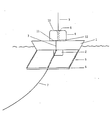
- FIG. 1 is a mainly disc shaped float body consisting of four circle segments applied around a cylindrical downwardly protruding housing 2. These segments can for instance be mounted by means of I-beams 3 which are fixedly connected to the wall of the housing 2.
- an auxiliary float body 4 is fixedly connected to the housing 2, which body 4 is coaxial to body 1 and has such a volume, that, when the buoy capsizes it lifts the total buoy just above the water.
- connection chains 5 are connected which themselves are connected to an anchoring member 6 that in this instance has the shape of a cross to the centre of which an anchor line 7 has been connected.
- auxiliary float body 4 Centrally in the auxiliary float body 4 a pass way 8 has been made through which an antenna 9 protrudes.
- auxiliary float body 4 mutually perpendicular radar reflector surfaces have been mounted, whereas the upper surface 10 and/or the lower surface 11 consist of a material reflecting electromagnetic wave or are covered with such a material.
- the antenna 9 protrudes through the pass way 8 which at its upper side is flared, it is supported at a location at a distance from its mounting point when it is bent, so that no local high stress will occur as would be the case if a sharp edge was present and practice has shown that herewith the normal but expensive and relatively vulnerable resilient mounting of the antenna is superfluous, which also could cause impendance matching problems.
- a buoy according the invention capsizes the buoyancy of the auxiliary float body 4 ensures that it is righted again. If by collision or suchlike severe damage occurs wherewith segments of the float body 1 can be lost, the rest of the buoy still floats by reason of the buoyancy of float body 4 and remains connected to the anchor line 7, because the housing 2, the I-beams 3 and the auxiliary float body form a mechanically strong unit.
- the pass way 8 can receive water, as well the water in which the buoy floats with heavy weather as rain, a scupper pass way 12 has been applied.
- the bottom of the auxiliary float body and the housing 2 forms a mechanical strong unit, for instance of steel.
- the reflector surfaces (not shown) in the float body 4 have a gap adjacent the pass way 8, it is true, but with a normal execution a sufficient surface remains for a well detectable radar reflection.
Landscapes
- Chemical & Material Sciences (AREA)
- Engineering & Computer Science (AREA)
- Combustion & Propulsion (AREA)
- Mechanical Engineering (AREA)
- Ocean & Marine Engineering (AREA)
- Chemical Kinetics & Catalysis (AREA)
- Details Of Aerials (AREA)
Claims (9)
Applications Claiming Priority (2)
| Application Number | Priority Date | Filing Date | Title |
|---|---|---|---|
| NL8100166A NL8100166A (nl) | 1981-01-15 | 1981-01-15 | Drijver, in het bijzonder een meetboei. |
| NL8100166 | 1981-01-15 |
Publications (2)
| Publication Number | Publication Date |
|---|---|
| EP0056673A1 EP0056673A1 (fr) | 1982-07-28 |
| EP0056673B1 true EP0056673B1 (fr) | 1985-05-29 |
Family
ID=19836865
Family Applications (1)
| Application Number | Title | Priority Date | Filing Date |
|---|---|---|---|
| EP82200043A Expired EP0056673B1 (fr) | 1981-01-15 | 1982-01-14 | Bouée |
Country Status (5)
| Country | Link |
|---|---|
| US (1) | US4639227A (fr) |
| EP (1) | EP0056673B1 (fr) |
| JP (1) | JPS57147993A (fr) |
| DE (1) | DE3263802D1 (fr) |
| NL (1) | NL8100166A (fr) |
Families Citing this family (10)
| Publication number | Priority date | Publication date | Assignee | Title |
|---|---|---|---|---|
| GB2369247B (en) * | 1990-05-02 | 2002-09-18 | Stc Plc | Sea surface antenna |
| USH1051H (en) | 1991-05-10 | 1992-05-05 | Government Of The United States | Antenna stabilizing buoy |
| US7100438B2 (en) * | 2004-07-06 | 2006-09-05 | General Electric Company | Method and apparatus for determining a site for an offshore wind turbine |
| US20070217867A1 (en) * | 2006-03-15 | 2007-09-20 | Son Rae S | Floating barriers for retaining substances in confined area, and barrier systems usable for treating oil spill in the water and for other applications |
| AU2008204779B2 (en) * | 2007-01-11 | 2012-01-12 | Statoilhydro Asa | A method and system for the protection of internal filters of a LTFT slurry bubble reactor |
| NL1035845C (en) | 2008-08-19 | 2010-03-10 | Thales Nederland Bv | SENSORS IN CONCERT FOR MARITIME SURVEILLANCE. |
| CA2870384C (fr) | 2012-04-15 | 2020-11-03 | Harbo Technologies Ltd. | Fleche de confinement de deversement de petrole a deplacement rapide et procede de deploiement |
| CN107075828A (zh) * | 2014-10-14 | 2017-08-18 | 哈勃技术有限公司 | 溢出围控栏栅 |
| CA3070786A1 (fr) | 2017-07-24 | 2019-01-31 | Harbo Technologies Ltd. | Prevention de propagation de deversements d'hydrocarbures par confinement immediat |
| CN108860477B (zh) * | 2018-04-30 | 2021-02-26 | 海宁市高级技工学校 | 海洋监测浮标中的锂电池组件 |
Family Cites Families (11)
| Publication number | Priority date | Publication date | Assignee | Title |
|---|---|---|---|---|
| FR1272816A (fr) * | 1960-11-04 | 1961-09-29 | Kidde Walter Co Ltd | Balise marine à érection par gonflage destinée à porter notamment un réflecteur de radar |
| US3360811A (en) * | 1965-10-22 | 1968-01-02 | Robert H. Bartlebaugh | Waterway marker |
| US3587103A (en) * | 1969-12-04 | 1971-06-22 | Garrett Corp | Stowable radio antenna |
| US3674225A (en) * | 1970-07-09 | 1972-07-04 | Us Army | Buoy |
| US3708982A (en) * | 1970-10-12 | 1973-01-09 | Ocean Systems | System and barrier for containing an oil spill |
| US3800601A (en) * | 1970-11-12 | 1974-04-02 | Us Navy | Sea sensor and descriptor system |
| US3775787A (en) * | 1972-10-19 | 1973-12-04 | C Rager | Buoy mooring device |
| JPS50149089A (fr) * | 1974-05-20 | 1975-11-28 | ||
| JPS5128918A (ja) * | 1974-09-03 | 1976-03-11 | Toyoda Automatic Loom Works | Fuookurifutotoratsukuniokeru sokosochi |
| US3916467A (en) * | 1974-11-07 | 1975-11-04 | Jr Robert F Curd | Fast water buoy |
| US4231131A (en) * | 1978-10-02 | 1980-11-04 | Young Eldon L | Inflatable high speed boat |
-
1981
- 1981-01-15 NL NL8100166A patent/NL8100166A/nl not_active Application Discontinuation
-
1982
- 1982-01-11 US US06/338,628 patent/US4639227A/en not_active Expired - Fee Related
- 1982-01-14 EP EP82200043A patent/EP0056673B1/fr not_active Expired
- 1982-01-14 DE DE8282200043T patent/DE3263802D1/de not_active Expired
- 1982-01-16 JP JP57005311A patent/JPS57147993A/ja active Pending
Also Published As
| Publication number | Publication date |
|---|---|
| EP0056673A1 (fr) | 1982-07-28 |
| NL8100166A (nl) | 1982-08-02 |
| DE3263802D1 (en) | 1985-07-04 |
| US4639227A (en) | 1987-01-27 |
| JPS57147993A (en) | 1982-09-13 |
Similar Documents
| Publication | Publication Date | Title |
|---|---|---|
| EP0056673B1 (fr) | Bouée | |
| ES2908316T3 (es) | Plataforma flotante para vigilancia marítima | |
| CA1238400A (fr) | Reflecteur radar triedre | |
| WO2007053007A1 (fr) | Dispositif permettant de determiner le niveau d'un liquide au moyen d'une antenne radar, et antenne radar correspondante | |
| US4148033A (en) | Radar reflector for buoys and other floating objects | |
| US20250074551A1 (en) | High-stability deep-sea buoy platform and an oscillation control method thereof | |
| US6664916B1 (en) | System and method for identifying navigational markers using radar | |
| US3672175A (en) | Ice cutter | |
| EP0325539A1 (fr) | Système de positionnement pour un objet en mouvement | |
| GB2123774A (en) | Stabilised underwater apparatus for being towed or tethered | |
| US3397413A (en) | Navigational marker | |
| US5838275A (en) | Marine personal locator and automatic opening omnidirectional radar retroreflector incorporated therein | |
| KR102532862B1 (ko) | 태양전지를 구비한 파고부이 | |
| KR200173327Y1 (ko) | 다기능 부체식 등부표 | |
| US2837753A (en) | Seadrome light support | |
| US2789382A (en) | Method and system for checking the position of fishing nets | |
| CN208731190U (zh) | 一种基于桅顶激光束的随船预警防撞装置及船舶 | |
| JP3323447B2 (ja) | データ伝送ブイ | |
| EP0032604A1 (fr) | Réflecteur radar | |
| CN220786067U (zh) | 一种水环境监测浮标 | |
| JPS60173903A (ja) | 全方向性レ−ダリフレクタ装置 | |
| RU2260885C1 (ru) | Радиолокационный уголковый отражатель | |
| JP3294205B2 (ja) | データ伝送ブイ | |
| US4498877A (en) | Anchoring system for a buoy, specially a measuring buoy | |
| CN224184453U (zh) | 一种可调节配重结构的钢制浮标 |
Legal Events
| Date | Code | Title | Description |
|---|---|---|---|
| PUAI | Public reference made under article 153(3) epc to a published international application that has entered the european phase |
Free format text: ORIGINAL CODE: 0009012 |
|
| AK | Designated contracting states |
Designated state(s): DE FR GB NL |
|
| 17P | Request for examination filed |
Effective date: 19820927 |
|
| GRAA | (expected) grant |
Free format text: ORIGINAL CODE: 0009210 |
|
| AK | Designated contracting states |
Designated state(s): DE FR GB NL |
|
| REF | Corresponds to: |
Ref document number: 3263802 Country of ref document: DE Date of ref document: 19850704 |
|
| ET | Fr: translation filed | ||
| PLBE | No opposition filed within time limit |
Free format text: ORIGINAL CODE: 0009261 |
|
| STAA | Information on the status of an ep patent application or granted ep patent |
Free format text: STATUS: NO OPPOSITION FILED WITHIN TIME LIMIT |
|
| 26N | No opposition filed | ||
| PGFP | Annual fee paid to national office [announced via postgrant information from national office to epo] |
Ref country code: FR Payment date: 19890127 Year of fee payment: 8 |
|
| PGFP | Annual fee paid to national office [announced via postgrant information from national office to epo] |
Ref country code: NL Payment date: 19890131 Year of fee payment: 10 Ref country code: GB Payment date: 19890131 Year of fee payment: 8 |
|
| PGFP | Annual fee paid to national office [announced via postgrant information from national office to epo] |
Ref country code: DE Payment date: 19890328 Year of fee payment: 8 |
|
| PG25 | Lapsed in a contracting state [announced via postgrant information from national office to epo] |
Ref country code: GB Effective date: 19900114 |
|
| PG25 | Lapsed in a contracting state [announced via postgrant information from national office to epo] |
Ref country code: NL Effective date: 19900801 |
|
| GBPC | Gb: european patent ceased through non-payment of renewal fee | ||
| NLV4 | Nl: lapsed or anulled due to non-payment of the annual fee | ||
| PG25 | Lapsed in a contracting state [announced via postgrant information from national office to epo] |
Ref country code: FR Effective date: 19900928 |
|
| PG25 | Lapsed in a contracting state [announced via postgrant information from national office to epo] |
Ref country code: DE Effective date: 19901002 |
|
| REG | Reference to a national code |
Ref country code: FR Ref legal event code: ST |