EP0056691A1 - Méthode et appareil de détection à résonance magnétique nucléaire - Google Patents
Méthode et appareil de détection à résonance magnétique nucléaire Download PDFInfo
- Publication number
- EP0056691A1 EP0056691A1 EP82300086A EP82300086A EP0056691A1 EP 0056691 A1 EP0056691 A1 EP 0056691A1 EP 82300086 A EP82300086 A EP 82300086A EP 82300086 A EP82300086 A EP 82300086A EP 0056691 A1 EP0056691 A1 EP 0056691A1
- Authority
- EP
- European Patent Office
- Prior art keywords
- coils
- plane
- picture
- producing
- magnetic field
- Prior art date
- Legal status (The legal status is an assumption and is not a legal conclusion. Google has not performed a legal analysis and makes no representation as to the accuracy of the status listed.)
- Granted
Links
- 238000001514 detection method Methods 0.000 title claims description 8
- 238000005481 NMR spectroscopy Methods 0.000 title description 20
- 238000000034 method Methods 0.000 claims abstract description 20
- 230000004044 response Effects 0.000 claims abstract description 20
- 238000012935 Averaging Methods 0.000 claims description 9
- 230000005855 radiation Effects 0.000 claims description 2
- 230000005284 excitation Effects 0.000 description 17
- 238000001208 nuclear magnetic resonance pulse sequence Methods 0.000 description 7
- 230000000694 effects Effects 0.000 description 6
- 238000003384 imaging method Methods 0.000 description 6
- 239000000126 substance Substances 0.000 description 6
- 238000012545 processing Methods 0.000 description 5
- 230000003068 static effect Effects 0.000 description 5
- 230000008901 benefit Effects 0.000 description 4
- 230000005415 magnetization Effects 0.000 description 4
- 230000008569 process Effects 0.000 description 4
- XLYOFNOQVPJJNP-UHFFFAOYSA-N water Substances O XLYOFNOQVPJJNP-UHFFFAOYSA-N 0.000 description 4
- 230000008859 change Effects 0.000 description 3
- 208000004209 confusion Diseases 0.000 description 3
- 230000001419 dependent effect Effects 0.000 description 3
- 206010013395 disorientation Diseases 0.000 description 3
- 238000004519 manufacturing process Methods 0.000 description 3
- 239000000463 material Substances 0.000 description 3
- 230000003534 oscillatory effect Effects 0.000 description 3
- 230000009471 action Effects 0.000 description 2
- 238000004458 analytical method Methods 0.000 description 2
- 230000001427 coherent effect Effects 0.000 description 2
- 238000013461 design Methods 0.000 description 2
- 238000010586 diagram Methods 0.000 description 2
- 238000002955 isolation Methods 0.000 description 2
- 239000007788 liquid Substances 0.000 description 2
- 230000010355 oscillation Effects 0.000 description 2
- 238000011084 recovery Methods 0.000 description 2
- 241000894007 species Species 0.000 description 2
- 230000036962 time dependent Effects 0.000 description 2
- UFHFLCQGNIYNRP-UHFFFAOYSA-N Hydrogen Chemical compound [H][H] UFHFLCQGNIYNRP-UHFFFAOYSA-N 0.000 description 1
- 206010033799 Paralysis Diseases 0.000 description 1
- 230000002159 abnormal effect Effects 0.000 description 1
- 238000010521 absorption reaction Methods 0.000 description 1
- 238000013459 approach Methods 0.000 description 1
- 239000008280 blood Substances 0.000 description 1
- 210000004369 blood Anatomy 0.000 description 1
- 210000004556 brain Anatomy 0.000 description 1
- 230000002301 combined effect Effects 0.000 description 1
- 238000010276 construction Methods 0.000 description 1
- 230000008878 coupling Effects 0.000 description 1
- 238000010168 coupling process Methods 0.000 description 1
- 238000005859 coupling reaction Methods 0.000 description 1
- 230000007423 decrease Effects 0.000 description 1
- 238000002059 diagnostic imaging Methods 0.000 description 1
- 230000008034 disappearance Effects 0.000 description 1
- 238000009826 distribution Methods 0.000 description 1
- 239000012530 fluid Substances 0.000 description 1
- 230000006870 function Effects 0.000 description 1
- 150000002431 hydrogen Chemical class 0.000 description 1
- 229910052739 hydrogen Inorganic materials 0.000 description 1
- 239000001257 hydrogen Substances 0.000 description 1
- 230000006698 induction Effects 0.000 description 1
- 230000003993 interaction Effects 0.000 description 1
- 238000005259 measurement Methods 0.000 description 1
- 230000007246 mechanism Effects 0.000 description 1
- 230000007170 pathology Effects 0.000 description 1
- 230000000737 periodic effect Effects 0.000 description 1
- 230000000704 physical effect Effects 0.000 description 1
- 238000003825 pressing Methods 0.000 description 1
- 230000003252 repetitive effect Effects 0.000 description 1
- 230000000717 retained effect Effects 0.000 description 1
- 229920006395 saturated elastomer Polymers 0.000 description 1
- 238000009738 saturating Methods 0.000 description 1
- 238000010187 selection method Methods 0.000 description 1
- 239000002689 soil Substances 0.000 description 1
- 239000007787 solid Substances 0.000 description 1
- 238000003756 stirring Methods 0.000 description 1
- 238000003860 storage Methods 0.000 description 1
- 230000001360 synchronised effect Effects 0.000 description 1
- 230000009466 transformation Effects 0.000 description 1
Images


Classifications
-
- G—PHYSICS
- G01—MEASURING; TESTING
- G01R—MEASURING ELECTRIC VARIABLES; MEASURING MAGNETIC VARIABLES
- G01R33/00—Arrangements or instruments for measuring magnetic variables
- G01R33/20—Arrangements or instruments for measuring magnetic variables involving magnetic resonance
- G01R33/44—Arrangements or instruments for measuring magnetic variables involving magnetic resonance using nuclear magnetic resonance [NMR]
- G01R33/445—MR involving a non-standard magnetic field B0, e.g. of low magnitude as in the earth's magnetic field or in nanoTesla spectroscopy, comprising a polarizing magnetic field for pre-polarisation, B0 with a temporal variation of its magnitude or direction such as field cycling of B0 or rotation of the direction of B0, or spatially inhomogeneous B0 like in fringe-field MR or in stray-field imaging
-
- G—PHYSICS
- G01—MEASURING; TESTING
- G01N—INVESTIGATING OR ANALYSING MATERIALS BY DETERMINING THEIR CHEMICAL OR PHYSICAL PROPERTIES
- G01N24/00—Investigating or analyzing materials by the use of nuclear magnetic resonance, electron paramagnetic resonance or other spin effects
- G01N24/008—Investigating or analyzing materials by the use of nuclear magnetic resonance, electron paramagnetic resonance or other spin effects by using resonance effects in zero field, e.g. in microwave, submillimetric region
-
- G—PHYSICS
- G01—MEASURING; TESTING
- G01R—MEASURING ELECTRIC VARIABLES; MEASURING MAGNETIC VARIABLES
- G01R33/00—Arrangements or instruments for measuring magnetic variables
- G01R33/20—Arrangements or instruments for measuring magnetic variables involving magnetic resonance
- G01R33/44—Arrangements or instruments for measuring magnetic variables involving magnetic resonance using nuclear magnetic resonance [NMR]
- G01R33/48—NMR imaging systems
- G01R33/54—Signal processing systems, e.g. using pulse sequences ; Generation or control of pulse sequences; Operator console
Definitions
- the present invention relates to Nuclear Magnetic Resonance (N.M.R.) detection methods and apparatus and more particularly to the production of an N.M.R. image of a plane through an object.
- N.M.R. Nuclear Magnetic Resonance
- N.M.R. detection techniques are useful in a number of different fields. A particular application is found in the detection of substances within a body, which substances are not detectable by normal X ray techniques. This may occur either because the region in which the substance is present is within a wall structure which is impenetrable by X rays or that the substance itself is not sufficiently different in density from the surroundings to be distinguished on an X ray photograph.
- N.M.R. The most useful operational description of N.M.R. that has been given so far is by a set of equations due to Bloch. These equation attempt to quantify the total magnetic behaviour of a collection of magnetic gyroscopes (nuclei) subjected to time varying and static magnetic fields.
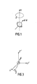
- the behaviour of a single isolated nucleus of magnetic momement ⁇ is that of a gyroscope i.e. it precesses at a frequency w (the LARMOR FREQUENCY) dependent on the mechanical couple that it experiences due to an applied magnetic field of magnitude H.
- the size of the couple is given by r ⁇ H and its sense is such as to continually try to align the moment ⁇ with the field H.
- the proton or hydrogen nucleus has been extensively used, because of its large magnetic moment and abundance in water, to make NMR images.
- the main use of such imaging techniques is in the medical field, following Damadian's suggestion, and the measurements of others, that the NMR characteristics of cancerous tissue differ from the surrounding normal tissue, and the realization that bio-chemical changes, mechanical obstructions to flow and abnormal flow of proton-containing materials such as blood are all visualizable by NMR.
- NMR images are representations of the NMR signal coming from different volume elements within say a plane of finite thickness through an object.
- the 'size' of the NMR signal from a given volume element is represented by the brightness of the associated picture element in a 2D representation of the particular plane through the object on a display device.
- the 'size' of the NMR signal from a volume element depends in a complicated way on the mode of excitation and detection of the NMR and on the precise method of obtaining the 'image' of say a plane. In the most general case the 'size' of the NMR signal from a volume element, hence the brightness of the particular associated picture element depends on:
- the equilibrium nuclear magnetic system in an extended object can be excited by 'resonant' RF pulses applied at or near the Larmor frequency. This is done by wrapping a coil around the object of a suitable design so that there is an oscillatory RF magnetic field present of amplitude h in the x direction at right angles to H , and uniform over the sample. This field h can be thought of as the sum of two rotatingfields in the xy plane of amplitude h/2.
- the RF pulse is switched on for a certain time then all the moments u (which are originally along the z' direction in equilibrium) will turn through the same angle 8, the RF pulse is then said to be a '8-pulse'. Note that a '90° pulse' will therefore turn all the nuclei to the y' direction from the z' direction and that further-more, the moments will all be aligned initially along y' with a large resultant magnetization M o .
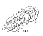
- Three further sets of coils 14, 16 and 18 are wound round the tube 10 at one end. EAch of the coils 14 and 16 are wound and then placed on to the outside surface of the tube 10 in the manner of a saddle. Taking coil 16 as an example the coil is shown as a single wire but will in practise be multi-turn.
- the coils, 14, 16 are basically rectangular in shape and the one side of the rectangular coil 16 is hidden in the construction by the tube 10 and is shown dotted.
- the coil 18 is cylindrical in shape and wound circumferentially round the tube 10.
- the coil pairs 14, 16 and 18 and 14', 16' and 18' are arranged to leave a portion of the tube 10 open in the centre.
- An exciter and receiver coil 20 is placed within the tube 10 on a cylindrical former 22.
- the object to be examined is the head of a person.
- the person is supported within the'tube 10 by means of a trolley 24 (shown in Fig 5) which preferably is slideable within the tube 10 to allow the person to be placed on khe support external to the tube and to be slid along the tube to a desired position.
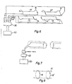
- FIG 5 the apparatus of figure 14 is shown in a schematic elevation view to illustrate the shape of the coils and to shown the major electrical drive generators for the coils.
- reference numerals are retained for the features present in several figures.
- the Y field coils, 14, 14' are supplied with energising current from a generator 30 and similarly the X and Z coils are supplied from generators 32, 34.
- the current can be D.C. or oscillating as selected.
- the main magnetising field coils 12, 12' are supplied with current from a D.C. high current power supply 36.
- connection between the control system 50 and each generator 30, 32 and 34 (for the Z coils) is shown as a multiple connection because it is required to control both magnitude and direction of the current in each coil and also whether the current is D.C. or oscillating.
- Figure 8 shows the direction of current in the Z coils which are supplied as shown in figure 5 by a generator 34 also controlled by the control system 50.
- the control system 50 gives signals--to the generators 30, 32 and 34 to enable the N.M.R. picture of a plane to be formed.
- the Y coils are shown connected as a upper pair and a lower pair. These can both be supplied with the same current or can be provided with different oscillating currents to move the flame. When supplied with D.C. the coils will all be supplied with the same current but when used to isolate the plane and supplied with oscillating currents they can be connected independently as shown and supplied with different currents.
- the X coils are operated in an connected in an identical manner.
- two of the coils are driven with DC current and connected in series and one is supplied with an oscillating current and each half of the coils may be supplied with different currents depending on the chosen plane.
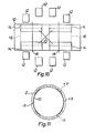
- FIG. 9 An example of the connections showing a transverse plane is shown in figure 9.
- one of the sets of coils must be supplied with an oscillating gradient.
- connectionsof the coils may be accomplished automatically on selectionof a plane by closure of appropriate relays to produce the required interconnections.
- the X and Y coils 14 and 16 "overlap" the sense and R.F. coil 22 and the main magnetising coil arrangement 12 comprises four annular coils arranged approximately in a circle to provide a uniform field in the centre of the - sense coil 22.
- each X and Y coil occupies 120° of arc and overlaps the adjacent Y or X coil by 30°.
- the coils are wound such that each X, Y and Z coil has the same reluctance and therefore they may be considered interchangeable from thepoint of view of being driven by the signal generators. This .is an extremely practical advantage because of the necessity to change the current generators between the X, Y and Z coils.
- the FID following a suitably broadband RF 90° excitation pulse (spanning w -63 to w 63 ) will thus clearly give a projection of the N.M.R. object on to the gradient direction since each strip of the plane contributes a frequency point on the projection as shown.
- the Fourier Transformation of the FID of a sample in a linear gradient is the one-dimensional projection of the N.M.R. object on to the gradient direction.
- the gradient G can be rotated through a finite angle, keeping its strength constant, and such that there is a unique point X within the object where for all positions of the gradient G, the total resultant field is unaffected and equal to the applied field, then a large number of accurate (because of the linearity of G and the existence of X) geometric projections of the N.M.R. object can be obtained from a number of discrete gradient directions.
- X-ray CT is an ABSORPTION image, not EMISSION as with N.M.R. It is important in projection reconstruction that all parts of the object are examined and contribute to all the projections for the reconstruction process to be predictably accurate. It is also important that at the edge of the object, for successive positions of G, or in the X-ray case for successive directions of the scanning motion that the 'resolution distance' required (or interstrip spacing) should overlap at least to the extent as shown in figure 11. These necessary and desirable conditions can be achieved in one embodiment by rotating the gradient G not in discrete steps averaging the N.M.R. signal at each position but CONTINUOUSLY with continuous averaging of the N.M.R. signal.
- the gradient direction can be moved rapidly from one position to the next followed by a sequence of RF pulses which saturate the N.M.R. signal, so that Averaging for a short period (say 0.5s) makes the averaged signal more dependent on the recovery time T 1 .
- the N.M.R. response is measured during successive intervals as the gradient rotates such that the worst-case N.M.R. frequency change during the averaging interval (at the extreme edge of the object) is less than the interstrip frequency chosen, which corresponds, via the field gradient strength G to the spatial resolution required.
- the means whereby the gradient G is rotated is by using the three sets of gradient producing coils 14, 16, 18 and 14', 16' and 18' wound on the patient support tube which have similar electrical characteristics and which produce uniform gradients (of Hz) in the three ( x , y, z) co-ordinate directions. Any pair of these can be selected and driven by cosinuosoidally and sinuosoidally varying currents respectively thus producing a uniformly rotating gradient of constant magnitude in either the xy, yz or zx planes.
- N.M.R. excitation used during the reconstruction process described above have a considerable bearing on its accuracy and efficacy. If 'multiple-sideband' derived methods are used where the N.M.R. excitation consists of a string of equally- spaced coherent phase alternated RF pulses, then the interstrip frequency clearly corresponds to the RF excitation sideband spacing, and in fact only half the imaged plane is being examined at any instant. If uniform RF excitation is used, by means of non-periodic pulse excitation sequences then this difficulty can be overcome.
- a preferred solution described in our copending application is to use alternative pulse sequences with unequally spaced unequal pulses that allow the extent to which the N.M.R. system is away from thermal equilibrium to be carefully controlled, which restores the ability to move the gradient G faster hence produce images in a shorter time. Such sequences also allow the gradient to be rotated in a discrete fashion, and by removing saturation effects, give larger signals.
- a further major advantage is that by variation of the excitation and averaging sequences in a programmably controllable way, N.M.R. images that exhibit a variable degree of contrast based on varying the influence of the four major N.M.R. parameters mentioned earlier, can be obtained. This will be of great use in determining the usefulness of N.M.R.
- N.M.R. imaging particularly proton N.M.R. imaging and more particularly in medical applications.
- a single oscillatory gradient is used to select the plane, postulated above, within which by reconstruction from N.M.R. projections, N.M.R. images may be produced.
- the problem here is to select from within a large object, like for instance the human head, a plane, from which signals are exclusively obtained continuously despite the fact that the whole object is excited by RF pulses fed to a coil system, and the detector coil is sensitive to N.M.R. occurring throughout the object.
- the method used could be called'selective saturation' and it depends for its success on the combined effect of the pulse sequences and the effect of one oscillating gradient.
- the detailed form of RF pulse excitation used is unimportant provided the pulse angles are not all much less than 90°.
- the oscillating gradient is such that there is a plane in space in which the resultant Hz field has no time dependence due to the gradient, and away from this plane, whose orient ion is in any selectable direction depending on the gradient coils that are selected, there is an ever increasing time dependent component of Hz.
- the detailed form of the RF excitation pulse sequence is unimportant, it is crucially important that the gradient oscillation frequency be asynchronous with respect to any of the pulse train periodicities.
- the effect of the pulses (wideband) in regions where Hz is varying is to rotate the nuclei through the same angles as in the plane region of constant Hz
- the pulses act in an almost stochastic way to stir up the precession angles of the nuclei in to an incoherent arrangement. 'The Bloch equations predict then that the net result of this is to saturate these regions provided 1/T, for the nuclei is less than the oscillating gradient frequency (i.e.
- the 'thickness' of the selected plane is controllable by variation of the amplitude of the oscillating gradient (the current amplitude fed to the gradient-producing coils).
- the position in space of the selected plane can be moved by arranging that the gradient field is produced by a pair of coil sets, which can be unequally driven so as to move the position of the null plane (where the fields from the two coil sets exactly cancel).
- Golay and Helmholtz derived coils are used for the x, y and z gradients respectively.
- the x and y coil sets are identical and have very similar inductance to the z set.
- images may be obtained in any plane, in any orientation, of any thickness and in any spatial position - a considerable advantage for example in the precise location of pathology in the head.
- FIG. 13 A preferred design of the R.F. coil for producing the N.M.R. response is shown in figure 13.
- the coils 40, 42, shown are crossed elliptical or crossed circular coil pairs wound round the tube 10. Crossed ellipses are illustrated but crossed circles can be obtained from them by pulling the cross over points of the two coils 40, 42 off the cylindrical tube 10 till the coils are circular.
- the power to the coils of the magnets defining the selected section is increased such that the selected section moves continuously and gradually at a relatively slow rate.
- R.F. pulses are provided at a relatively high pulse repition rate such that for example 200 to 300 pulses are received whilst the gradient angle moves through 1°.
- the output of each of the pulses is stored and the average N.M.R. output over the 200 pulses is calculated and used to produce the total N.M.R. picture with averaged pulses from the other angles.
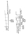
- Figure 17 shows in the upper portion the gradually increasing gradient angle and on the lower portion the relatively high frequency R.F. pulses.
- the x and y coils are supplied with a fixed voltage to maintain the gradient angle fixed for a defined period during which between 200 and 300 R.F. pulses are provided to produce N.M.R. signals from the object being examined.
- the signals supplied to the x and y coils are incremented and the gradient angle is changed in a step manner through 1° as shown in the upper trace in figure 18.
- the average N.M.R. signal is therefore measured over the time period following the early disorientation period.
- FIG 19 there is shown a block diagram of the major electrical components.
- the various coils are indicated by boxes for simplicity but they will be as shownin the preceding figures 4 etc. Where possible parts if figure 19 are given the same reference numerals as in figure 5 to indicate the correspondence between the figures.
- the Central Processing unit 60 runs in time with the rest of the system under the control of a master oscillator and clock generator 62 and the Central Processing Unit 60 controls the system via a data bus 64.
- the N.M.R. signal received from the R.F. coil 22 passes via the passive duplex unit 40 to an R.F. receiver 66 which amplifies the signal and feeds the amplified signal to the R.F. phase detector 42.
- the outputs of the detector 42 are fed to the averager 68 and the outputs of the averager are stored in the storage unit 70.
- the N.M.R. picture is formed from the averaged samples of the individual N.M.R. responses as described with reference to figures 17 or 18 according to the program sequence shown in figure 20.
- the program is simple and considered mostly self explanatory.
- the processing within the Central Processing Unit 60 is done in real time whilst the subsequent pulses are delivered to the R.F. coil to produce the next averaged output.
Landscapes
- Physics & Mathematics (AREA)
- General Physics & Mathematics (AREA)
- High Energy & Nuclear Physics (AREA)
- Condensed Matter Physics & Semiconductors (AREA)
- Analytical Chemistry (AREA)
- Health & Medical Sciences (AREA)
- Life Sciences & Earth Sciences (AREA)
- Chemical & Material Sciences (AREA)
- Spectroscopy & Molecular Physics (AREA)
- Biochemistry (AREA)
- General Health & Medical Sciences (AREA)
- Immunology (AREA)
- Pathology (AREA)
- Engineering & Computer Science (AREA)
- Signal Processing (AREA)
- Magnetic Resonance Imaging Apparatus (AREA)
Applications Claiming Priority (8)
| Application Number | Priority Date | Filing Date | Title |
|---|---|---|---|
| GB8101172 | 1981-01-15 | ||
| GB8101172 | 1981-01-15 | ||
| GB8101173 | 1981-01-15 | ||
| GB8101173 | 1981-01-15 | ||
| GB8101176 | 1981-02-02 | ||
| GB8101175 | 1981-02-02 | ||
| GB8101176 | 1981-02-02 | ||
| GB8101175 | 1981-02-02 |
Publications (2)
| Publication Number | Publication Date |
|---|---|
| EP0056691A1 true EP0056691A1 (fr) | 1982-07-28 |
| EP0056691B1 EP0056691B1 (fr) | 1986-04-09 |
Family
ID=27449222
Family Applications (1)
| Application Number | Title | Priority Date | Filing Date |
|---|---|---|---|
| EP82300086A Expired EP0056691B1 (fr) | 1981-01-15 | 1982-01-08 | Méthode et appareil de détection à résonance magnétique nucléaire |
Country Status (3)
| Country | Link |
|---|---|
| US (1) | US4475084A (fr) |
| EP (1) | EP0056691B1 (fr) |
| DE (1) | DE3270330D1 (fr) |
Cited By (3)
| Publication number | Priority date | Publication date | Assignee | Title |
|---|---|---|---|---|
| EP0152588A1 (fr) * | 1984-02-20 | 1985-08-28 | Siemens Aktiengesellschaft | Système de bobines à gradients d'un dispositif pour la tomographie à spin nucléaire |
| EP0129356A3 (fr) * | 1983-06-20 | 1985-12-04 | Picker International Limited | Procédé et appareil de résonance magnétique nucléaire |
| US4812796A (en) * | 1987-03-30 | 1989-03-14 | Siemens Aktiengesellschaft | Quench propagation device for a superconducting magnet |
Families Citing this family (23)
| Publication number | Priority date | Publication date | Assignee | Title |
|---|---|---|---|---|
| EP0106472B1 (fr) * | 1982-09-17 | 1988-12-07 | Picker International Limited | Procédé et appareil de résonance magnétique nucléaire |
| JPS5985651A (ja) * | 1982-11-08 | 1984-05-17 | 株式会社東芝 | 診断用核磁気共鳴装置 |
| US4565968A (en) * | 1983-02-16 | 1986-01-21 | Albert Macovski | Blood vessel projection imaging system using nuclear magnetic resonance |
| US4549140A (en) * | 1983-06-03 | 1985-10-22 | General Electric Company | Method utilizing combined, interleaved pulse sequences for reducing motion artifacts in computed T1,T2 and M0 NMR imaging |
| US4549139A (en) * | 1983-06-03 | 1985-10-22 | General Electric Company | Method of accurate and rapid NMR imaging of computed T1 and spin density |
| US4628263A (en) * | 1983-06-13 | 1986-12-09 | Jeol Ltd. | Nuclear magnetic resonance spectrometer |
| US4613818A (en) * | 1983-06-20 | 1986-09-23 | The Medical College Of Wisconsin, Inc. | Nuclear magnetic resonance blood flowmeter |
| GB8321236D0 (en) * | 1983-08-05 | 1983-09-07 | Technicare Corp | Gradient null displacement coil |
| US4817612A (en) * | 1983-08-14 | 1989-04-04 | University Of Florida | Cross-coupled double loop receiver coil for NMR imaging of cardiac and thoraco-abdominal regions of the human body |
| US4646024A (en) * | 1983-11-02 | 1987-02-24 | General Electric Company | Transverse gradient field coils for nuclear magnetic resonance imaging |
| US4840700A (en) * | 1983-11-02 | 1989-06-20 | General Electric Company | Current streamline method for coil construction |
| US4682112A (en) * | 1984-10-10 | 1987-07-21 | Elscint Ltd. | NMR antenna and method for designing the same |
| US4665366A (en) * | 1985-03-11 | 1987-05-12 | Albert Macovski | NMR imaging system using phase-shifted signals |
| US4709212A (en) * | 1986-01-03 | 1987-11-24 | General Electric Company | Method of enhancing image signal-to-noise ratio by combining NMR images of differing pulse sequence timing |
| US4766383A (en) * | 1987-02-24 | 1988-08-23 | Kabushiki Kaisha Toshiba | Quadrature antenna for magnetic resonance imaging using elliptical coils |
| US4755755A (en) * | 1987-02-27 | 1988-07-05 | The Regents Of The University Of California | Compact transverse magnetic gradient coils and dimensioning method therefor |
| ES2058714T3 (es) * | 1987-06-23 | 1994-11-01 | Nycomed Innovation Ab | Mejoras introducidas en formacion de imagenes por resonancia magnetica. |
| JP2957237B2 (ja) * | 1990-06-22 | 1999-10-04 | 株式会社東芝 | 磁気共鳴イメージング装置 |
| US6836118B2 (en) * | 2000-03-10 | 2004-12-28 | Mri Devices Corp. | Method and apparatus for NMR imaging |
| US7253627B1 (en) | 2006-07-19 | 2007-08-07 | Univ King Fahd Pet & Minerals | Method for removing noise from nuclear magnetic resonance signals and images |
| WO2008154059A2 (fr) * | 2007-04-02 | 2008-12-18 | Regents Of The University Of California | Champs de gradient à trame tournante pour une imagerie par résonance magnétique et résonance magnétique nucléaire dans des champs bas |
| DE102011076918B4 (de) * | 2011-06-03 | 2019-03-21 | Siemens Healthcare Gmbh | Lokalspulensystem, Magnetresonanzsystem und Verfahren zur drahtlosen Energieübertragung zu einem Lokalspulensystem |
| US10132894B2 (en) * | 2012-01-11 | 2018-11-20 | Schlumberger Technology Corporation | Magnetic resonance imaging methods |
Citations (5)
| Publication number | Priority date | Publication date | Assignee | Title |
|---|---|---|---|---|
| NL7905614A (nl) * | 1978-07-20 | 1980-01-22 | Univ California | Werkwijze en inrichting voor het optekenen van lijnen van nucleaire dichtheid binnen een voorwerp onder gebruikmaking van nucleaire magnetische resonantie. |
| DE2946820A1 (de) * | 1978-11-16 | 1980-05-29 | Emi Ltd | Verfahren und vorrichtung zur untersuchung eines koerpers mittels nuklearer magnetischer resonanz |
| GB2037996A (en) * | 1978-11-16 | 1980-07-16 | Emi Ltd | Improvements in or relating to imaging systems |
| GB2049947A (en) * | 1979-03-13 | 1980-12-31 | Emi Ltd | Improvements in or relating to imaging systems |
| GB2056078A (en) * | 1979-08-03 | 1981-03-11 | Emi Ltd | Nuclear magnetic resonance systems |
Family Cites Families (2)
| Publication number | Priority date | Publication date | Assignee | Title |
|---|---|---|---|---|
| GB1601816A (en) * | 1977-05-27 | 1981-11-04 | Nat Res Dev | Investigation of samples by nmr techniques |
| GB1578910A (en) * | 1978-05-25 | 1980-11-12 | Emi Ltd | Imaging systems |
-
1982
- 1982-01-05 US US06/337,184 patent/US4475084A/en not_active Expired - Fee Related
- 1982-01-08 EP EP82300086A patent/EP0056691B1/fr not_active Expired
- 1982-01-08 DE DE8282300086T patent/DE3270330D1/de not_active Expired
Patent Citations (8)
| Publication number | Priority date | Publication date | Assignee | Title |
|---|---|---|---|---|
| NL7905614A (nl) * | 1978-07-20 | 1980-01-22 | Univ California | Werkwijze en inrichting voor het optekenen van lijnen van nucleaire dichtheid binnen een voorwerp onder gebruikmaking van nucleaire magnetische resonantie. |
| GB2026172A (en) * | 1978-07-20 | 1980-01-30 | Univ California | Method and apparatus for determining the relative densities of nuclei within an object using nuclear magnetic resonance |
| DE2928551A1 (de) * | 1978-07-20 | 1980-01-31 | Univ California | Verfahren und vorrichtung zum aufzeichnen von linien der atomkerndichte innerhalb eines objekts unter anwendung der magnetischen kernresonanz |
| FR2431697A1 (fr) * | 1978-07-20 | 1980-02-15 | Univ California | Procede et appareil de determination des densites de noyaux par echo de spin pour elaboration de tomogrammes |
| DE2946820A1 (de) * | 1978-11-16 | 1980-05-29 | Emi Ltd | Verfahren und vorrichtung zur untersuchung eines koerpers mittels nuklearer magnetischer resonanz |
| GB2037996A (en) * | 1978-11-16 | 1980-07-16 | Emi Ltd | Improvements in or relating to imaging systems |
| GB2049947A (en) * | 1979-03-13 | 1980-12-31 | Emi Ltd | Improvements in or relating to imaging systems |
| GB2056078A (en) * | 1979-08-03 | 1981-03-11 | Emi Ltd | Nuclear magnetic resonance systems |
Cited By (3)
| Publication number | Priority date | Publication date | Assignee | Title |
|---|---|---|---|---|
| EP0129356A3 (fr) * | 1983-06-20 | 1985-12-04 | Picker International Limited | Procédé et appareil de résonance magnétique nucléaire |
| EP0152588A1 (fr) * | 1984-02-20 | 1985-08-28 | Siemens Aktiengesellschaft | Système de bobines à gradients d'un dispositif pour la tomographie à spin nucléaire |
| US4812796A (en) * | 1987-03-30 | 1989-03-14 | Siemens Aktiengesellschaft | Quench propagation device for a superconducting magnet |
Also Published As
| Publication number | Publication date |
|---|---|
| DE3270330D1 (en) | 1986-05-15 |
| EP0056691B1 (fr) | 1986-04-09 |
| US4475084A (en) | 1984-10-02 |
Similar Documents
| Publication | Publication Date | Title |
|---|---|---|
| US4475084A (en) | Nuclear magnetic resonance detector | |
| US4516075A (en) | NMR scanner with motion zeugmatography | |
| US5365172A (en) | Methods and apparatus for MRI | |
| US4318043A (en) | Method and apparatus for rapid NMR imaging of nuclear densities within an object | |
| EP0091008B1 (fr) | Méthode de formation d'image RMN en trois dimensions utilisant une excitation sélective | |
| US4297637A (en) | Method and apparatus for mapping lines of nuclear density within an object using nuclear magnetic resonance | |
| US4315216A (en) | Imaging systems | |
| EP0086972B2 (fr) | Méthode de formation d'images à RMN surmontant les effets T2* dans un champ magnétique statique non-homogène | |
| USRE32701E (en) | NMR scanner with motion zeugmatography | |
| JPH027655B2 (fr) | ||
| US4697147A (en) | Blood flow imaging using a CW NMR technique | |
| JPS6042906B2 (ja) | サンプルの核磁気共鳴スピン密度分布を表わす信号を取り出す方法 | |
| US4654591A (en) | NMR flow imaging using bi-phasic excitation field gradients | |
| US4716367A (en) | Creation and use of a moving reference frame for NMR imaging of flow | |
| US5578921A (en) | Magnetic resonance imaging using three-dimensional spectral-spatial excitation | |
| US4418316A (en) | Nuclear magnetic resonance apparatus | |
| EP0182481A2 (fr) | Procédé et dispositif pour la détermination de l'écoulement de fluides à l'aide de la résonance magnétique nucléaire | |
| EP0166559B1 (fr) | Procédé et appareil pour l'obtention de spectres localisés de résonance magnétique nucléaire | |
| USH1218H (en) | NMR imaging with varying spatial coupling | |
| HUP0202281A2 (en) | Method for generating measurement signals in magnetic fields | |
| US5317262A (en) | Single shot magnetic resonance method to measure diffusion, flow and/or motion | |
| Moore et al. | Experimental considerations in implementing a whole body multiple sensitive point nuclear magnetic resonance imaging system | |
| GB2091424A (en) | Nuclear Magnetic Resonance Imaging | |
| Wind et al. | Spatial selection in NMR by spin-locking | |
| CA1203282A (fr) | Scannographe rmn pouvant observer les mouvements par zeugmatographie |
Legal Events
| Date | Code | Title | Description |
|---|---|---|---|
| PUAI | Public reference made under article 153(3) epc to a published international application that has entered the european phase |
Free format text: ORIGINAL CODE: 0009012 |
|
| AK | Designated contracting states |
Designated state(s): DE FR NL |
|
| 17P | Request for examination filed |
Effective date: 19830113 |
|
| GRAA | (expected) grant |
Free format text: ORIGINAL CODE: 0009210 |
|
| AK | Designated contracting states |
Kind code of ref document: B1 Designated state(s): DE FR NL |
|
| ET | Fr: translation filed | ||
| REF | Corresponds to: |
Ref document number: 3270330 Country of ref document: DE Date of ref document: 19860515 |
|
| PGFP | Annual fee paid to national office [announced via postgrant information from national office to epo] |
Ref country code: NL Payment date: 19870131 Year of fee payment: 6 |
|
| PLBE | No opposition filed within time limit |
Free format text: ORIGINAL CODE: 0009261 |
|
| STAA | Information on the status of an ep patent application or granted ep patent |
Free format text: STATUS: NO OPPOSITION FILED WITHIN TIME LIMIT |
|
| 26N | No opposition filed | ||
| PG25 | Lapsed in a contracting state [announced via postgrant information from national office to epo] |
Ref country code: NL Effective date: 19890801 |
|
| NLV4 | Nl: lapsed or anulled due to non-payment of the annual fee | ||
| PG25 | Lapsed in a contracting state [announced via postgrant information from national office to epo] |
Ref country code: FR Free format text: LAPSE BECAUSE OF NON-PAYMENT OF DUE FEES Effective date: 19890929 |
|
| PG25 | Lapsed in a contracting state [announced via postgrant information from national office to epo] |
Ref country code: DE Effective date: 19891003 |
|
| REG | Reference to a national code |
Ref country code: FR Ref legal event code: ST |