EP0056737A2 - Method of manufacturing a semiconductor device using molecular beam epitaxy - Google Patents
Method of manufacturing a semiconductor device using molecular beam epitaxy Download PDFInfo
- Publication number
- EP0056737A2 EP0056737A2 EP82300288A EP82300288A EP0056737A2 EP 0056737 A2 EP0056737 A2 EP 0056737A2 EP 82300288 A EP82300288 A EP 82300288A EP 82300288 A EP82300288 A EP 82300288A EP 0056737 A2 EP0056737 A2 EP 0056737A2
- Authority
- EP
- European Patent Office
- Prior art keywords
- substrate
- evaporation
- layer
- film
- semiconductor device
- Prior art date
- Legal status (The legal status is an assumption and is not a legal conclusion. Google has not performed a legal analysis and makes no representation as to the accuracy of the status listed.)
- Withdrawn
Links
Images

Classifications
-
- H—ELECTRICITY
- H10—SEMICONDUCTOR DEVICES; ELECTRIC SOLID-STATE DEVICES NOT OTHERWISE PROVIDED FOR
- H10D—INORGANIC ELECTRIC SEMICONDUCTOR DEVICES
- H10D30/00—Field-effect transistors [FET]
- H10D30/01—Manufacture or treatment
- H10D30/021—Manufacture or treatment of FETs having insulated gates [IGFET]
- H10D30/031—Manufacture or treatment of FETs having insulated gates [IGFET] of thin-film transistors [TFT]
- H10D30/0312—Manufacture or treatment of FETs having insulated gates [IGFET] of thin-film transistors [TFT] characterised by the gate electrodes
- H10D30/0314—Manufacture or treatment of FETs having insulated gates [IGFET] of thin-film transistors [TFT] characterised by the gate electrodes of lateral top-gate TFTs comprising only a single gate
-
- C—CHEMISTRY; METALLURGY
- C23—COATING METALLIC MATERIAL; COATING MATERIAL WITH METALLIC MATERIAL; CHEMICAL SURFACE TREATMENT; DIFFUSION TREATMENT OF METALLIC MATERIAL; COATING BY VACUUM EVAPORATION, BY SPUTTERING, BY ION IMPLANTATION OR BY CHEMICAL VAPOUR DEPOSITION, IN GENERAL; INHIBITING CORROSION OF METALLIC MATERIAL OR INCRUSTATION IN GENERAL
- C23C—COATING METALLIC MATERIAL; COATING MATERIAL WITH METALLIC MATERIAL; SURFACE TREATMENT OF METALLIC MATERIAL BY DIFFUSION INTO THE SURFACE, BY CHEMICAL CONVERSION OR SUBSTITUTION; COATING BY VACUUM EVAPORATION, BY SPUTTERING, BY ION IMPLANTATION OR BY CHEMICAL VAPOUR DEPOSITION, IN GENERAL
- C23C14/00—Coating by vacuum evaporation, by sputtering or by ion implantation of the coating forming material
- C23C14/22—Coating by vacuum evaporation, by sputtering or by ion implantation of the coating forming material characterised by the process of coating
- C23C14/56—Apparatus specially adapted for continuous coating; Arrangements for maintaining the vacuum, e.g. vacuum locks
-
- H—ELECTRICITY
- H10—SEMICONDUCTOR DEVICES; ELECTRIC SOLID-STATE DEVICES NOT OTHERWISE PROVIDED FOR
- H10D—INORGANIC ELECTRIC SEMICONDUCTOR DEVICES
- H10D30/00—Field-effect transistors [FET]
- H10D30/01—Manufacture or treatment
- H10D30/021—Manufacture or treatment of FETs having insulated gates [IGFET]
- H10D30/031—Manufacture or treatment of FETs having insulated gates [IGFET] of thin-film transistors [TFT]
- H10D30/0321—Manufacture or treatment of FETs having insulated gates [IGFET] of thin-film transistors [TFT] comprising silicon, e.g. amorphous silicon or polysilicon
-
- H—ELECTRICITY
- H10—SEMICONDUCTOR DEVICES; ELECTRIC SOLID-STATE DEVICES NOT OTHERWISE PROVIDED FOR
- H10P—GENERIC PROCESSES OR APPARATUS FOR THE MANUFACTURE OR TREATMENT OF DEVICES COVERED BY CLASS H10
- H10P14/00—Formation of materials, e.g. in the shape of layers or pillars
- H10P14/20—Formation of materials, e.g. in the shape of layers or pillars of semiconductor materials
- H10P14/22—Formation of materials, e.g. in the shape of layers or pillars of semiconductor materials using physical deposition, e.g. vacuum deposition or sputtering
-
- H—ELECTRICITY
- H10—SEMICONDUCTOR DEVICES; ELECTRIC SOLID-STATE DEVICES NOT OTHERWISE PROVIDED FOR
- H10P—GENERIC PROCESSES OR APPARATUS FOR THE MANUFACTURE OR TREATMENT OF DEVICES COVERED BY CLASS H10
- H10P14/00—Formation of materials, e.g. in the shape of layers or pillars
- H10P14/20—Formation of materials, e.g. in the shape of layers or pillars of semiconductor materials
- H10P14/29—Formation of materials, e.g. in the shape of layers or pillars of semiconductor materials characterised by the substrates
- H10P14/2901—Materials
- H10P14/2902—Materials being Group IVA materials
- H10P14/2905—Silicon, silicon germanium or germanium
-
- H—ELECTRICITY
- H10—SEMICONDUCTOR DEVICES; ELECTRIC SOLID-STATE DEVICES NOT OTHERWISE PROVIDED FOR
- H10P—GENERIC PROCESSES OR APPARATUS FOR THE MANUFACTURE OR TREATMENT OF DEVICES COVERED BY CLASS H10
- H10P14/00—Formation of materials, e.g. in the shape of layers or pillars
- H10P14/20—Formation of materials, e.g. in the shape of layers or pillars of semiconductor materials
- H10P14/29—Formation of materials, e.g. in the shape of layers or pillars of semiconductor materials characterised by the substrates
- H10P14/2901—Materials
- H10P14/2922—Materials being non-crystalline insulating materials, e.g. glass or polymers
-
- H—ELECTRICITY
- H10—SEMICONDUCTOR DEVICES; ELECTRIC SOLID-STATE DEVICES NOT OTHERWISE PROVIDED FOR
- H10P—GENERIC PROCESSES OR APPARATUS FOR THE MANUFACTURE OR TREATMENT OF DEVICES COVERED BY CLASS H10
- H10P14/00—Formation of materials, e.g. in the shape of layers or pillars
- H10P14/20—Formation of materials, e.g. in the shape of layers or pillars of semiconductor materials
- H10P14/32—Formation of materials, e.g. in the shape of layers or pillars of semiconductor materials characterised by intermediate layers between substrates and deposited layers
- H10P14/3202—Materials thereof
- H10P14/3204—Materials thereof being Group IVA semiconducting materials
- H10P14/3211—Silicon, silicon germanium or germanium
-
- H—ELECTRICITY
- H10—SEMICONDUCTOR DEVICES; ELECTRIC SOLID-STATE DEVICES NOT OTHERWISE PROVIDED FOR
- H10P—GENERIC PROCESSES OR APPARATUS FOR THE MANUFACTURE OR TREATMENT OF DEVICES COVERED BY CLASS H10
- H10P14/00—Formation of materials, e.g. in the shape of layers or pillars
- H10P14/20—Formation of materials, e.g. in the shape of layers or pillars of semiconductor materials
- H10P14/32—Formation of materials, e.g. in the shape of layers or pillars of semiconductor materials characterised by intermediate layers between substrates and deposited layers
- H10P14/3202—Materials thereof
- H10P14/3238—Materials thereof being insulating materials
-
- H—ELECTRICITY
- H10—SEMICONDUCTOR DEVICES; ELECTRIC SOLID-STATE DEVICES NOT OTHERWISE PROVIDED FOR
- H10P—GENERIC PROCESSES OR APPARATUS FOR THE MANUFACTURE OR TREATMENT OF DEVICES COVERED BY CLASS H10
- H10P14/00—Formation of materials, e.g. in the shape of layers or pillars
- H10P14/20—Formation of materials, e.g. in the shape of layers or pillars of semiconductor materials
- H10P14/32—Formation of materials, e.g. in the shape of layers or pillars of semiconductor materials characterised by intermediate layers between substrates and deposited layers
- H10P14/3202—Materials thereof
- H10P14/3241—Materials thereof being conductive materials
-
- H—ELECTRICITY
- H10—SEMICONDUCTOR DEVICES; ELECTRIC SOLID-STATE DEVICES NOT OTHERWISE PROVIDED FOR
- H10P—GENERIC PROCESSES OR APPARATUS FOR THE MANUFACTURE OR TREATMENT OF DEVICES COVERED BY CLASS H10
- H10P14/00—Formation of materials, e.g. in the shape of layers or pillars
- H10P14/20—Formation of materials, e.g. in the shape of layers or pillars of semiconductor materials
- H10P14/34—Deposited materials, e.g. layers
- H10P14/3402—Deposited materials, e.g. layers characterised by the chemical composition
- H10P14/3404—Deposited materials, e.g. layers characterised by the chemical composition being Group IVA materials
- H10P14/3411—Silicon, silicon germanium or germanium
-
- H—ELECTRICITY
- H10—SEMICONDUCTOR DEVICES; ELECTRIC SOLID-STATE DEVICES NOT OTHERWISE PROVIDED FOR
- H10P—GENERIC PROCESSES OR APPARATUS FOR THE MANUFACTURE OR TREATMENT OF DEVICES COVERED BY CLASS H10
- H10P14/00—Formation of materials, e.g. in the shape of layers or pillars
- H10P14/40—Formation of materials, e.g. in the shape of layers or pillars of conductive or resistive materials
- H10P14/412—Deposition of metallic or metal-silicide materials
-
- H—ELECTRICITY
- H10—SEMICONDUCTOR DEVICES; ELECTRIC SOLID-STATE DEVICES NOT OTHERWISE PROVIDED FOR
- H10P—GENERIC PROCESSES OR APPARATUS FOR THE MANUFACTURE OR TREATMENT OF DEVICES COVERED BY CLASS H10
- H10P14/00—Formation of materials, e.g. in the shape of layers or pillars
- H10P14/60—Formation of materials, e.g. in the shape of layers or pillars of insulating materials
- H10P14/63—Formation of materials, e.g. in the shape of layers or pillars of insulating materials characterised by the formation processes
- H10P14/6326—Deposition processes
- H10P14/6328—Deposition from the gas or vapour phase
- H10P14/6332—Deposition from the gas or vapour phase using thermal evaporation
-
- H—ELECTRICITY
- H10—SEMICONDUCTOR DEVICES; ELECTRIC SOLID-STATE DEVICES NOT OTHERWISE PROVIDED FOR
- H10P—GENERIC PROCESSES OR APPARATUS FOR THE MANUFACTURE OR TREATMENT OF DEVICES COVERED BY CLASS H10
- H10P14/00—Formation of materials, e.g. in the shape of layers or pillars
- H10P14/60—Formation of materials, e.g. in the shape of layers or pillars of insulating materials
- H10P14/69—Inorganic materials
- H10P14/692—Inorganic materials composed of oxides, glassy oxides or oxide-based glasses
- H10P14/6921—Inorganic materials composed of oxides, glassy oxides or oxide-based glasses containing silicon
- H10P14/69215—Inorganic materials composed of oxides, glassy oxides or oxide-based glasses containing silicon the material being a silicon oxide, e.g. SiO2
-
- H—ELECTRICITY
- H10—SEMICONDUCTOR DEVICES; ELECTRIC SOLID-STATE DEVICES NOT OTHERWISE PROVIDED FOR
- H10P—GENERIC PROCESSES OR APPARATUS FOR THE MANUFACTURE OR TREATMENT OF DEVICES COVERED BY CLASS H10
- H10P14/00—Formation of materials, e.g. in the shape of layers or pillars
- H10P14/60—Formation of materials, e.g. in the shape of layers or pillars of insulating materials
- H10P14/69—Inorganic materials
- H10P14/692—Inorganic materials composed of oxides, glassy oxides or oxide-based glasses
- H10P14/6938—Inorganic materials composed of oxides, glassy oxides or oxide-based glasses the material containing at least one metal element, e.g. metal oxides, metal oxynitrides or metal oxycarbides
- H10P14/6939—Inorganic materials composed of oxides, glassy oxides or oxide-based glasses the material containing at least one metal element, e.g. metal oxides, metal oxynitrides or metal oxycarbides characterised by the metal
- H10P14/69391—Inorganic materials composed of oxides, glassy oxides or oxide-based glasses the material containing at least one metal element, e.g. metal oxides, metal oxynitrides or metal oxycarbides characterised by the metal the material containing aluminium, e.g. Al2O3
Definitions
- This invention relates to a method of manufacturing a semiconductor device employing evaporation under ultra-high vacuum (usually called "molecular-beam epitaxy process" - abbreviated to MBE process).
- the present invention provides a method of manufacturing a semiconductor device, including the step of evacuating a vacuum vessel to an ultra-high vacuum, the vessel containing a first evaporation source and a substrate having a surface onto which a layer is to be evaporated; and the step of forming a first evaporation layer on said surface using the first evaporation source; characterised in that the vacuum vessel contains at least a second evaporation source, and the method includes the step of subsequently forming a second evaporation layer on the first evaporation layer, using the second evaporation source, without removing the substrate from the vacuum vessel between the formation of the first and second evaporation layers.
- One of the evaporation sources can be a semiconductor material and another an insulator material.
- the pressure of the vacuum is at most 10 Torr.
- further substances can be evaporated into multilayer films as may be needed.
- the size of the semiconductor device is limited first by the size of the substrate.
- a silicon substrate is limited to a size of approximately 75 mm x 75 mm.
- the present invention forms multilayer films consecutively within the same vessel, the films do not touch the outside air containing many contamination sources, and hence, not only the formed films themselves but also the interfaces of the respective films are kept clean. For this reason, the multilayer films obtained are free from the occurrence of a surface state, are very stable without fluctuations and exhibit good characteristics. More specifically, it is a matter of course that when adsorbed in a film to be'formed, residual gases such as the air degrade the characteristics of the film. Even when a film has been formed clean, once the film is exposed to the outside air or the like, various kinds of molecules contained in the atmosphere adhere to the surface thereof. When a further film is formed with the molecules left adherent, these molecules degrade the respective films directly or indirectly.
- the multilayer films which have been formed bearing the impure molecules etc. in this manner are used in a device, they have evil effects on the electr.ical characteristics of the device such as the threshold voltage and the breakdown voltage or on the design and control of the device. With our preferred multilayer films, factors allowing such degradation are fully eliminated, and good multilayer films can be formed without any such problems.
- Such multilayer films are very effective when utilised for the formation of a semiconductor device, especially a semiconductor element sensitive to the surface state, such as MOSFET (MOS type Field Effect Transistor).
- MOSFET MOS type Field Effect Transistor
- the mean free path is several km to several hundred km, and the scattering molecules are not hindered by the foreign residual gas molecules or impurity atoms, so that they are grown on the glass as a crystal.
- the substrate is below room temperature, kinetic energy required for the crystallisation is insufficient, and the growth of a crystal film of good quality is not attained.
- the softening point of the substrate glass is exceeded, the substrate is melted or transformed, so that the crystal film is not grown.
- the glass substrate is not a crystalline body, but it is usually a non-crystalline body (amorphous or vitreous). In the ultra-high vacuum atmosphere,. however, the film to be formed on the glass substrate has the property of becoming a crystal layer as stated before.
- the degree of vacuum during the evaporation is suitably below 1 x 10 -8 Torr in terms of pressure, and the partial pressure of oxygen is below 1 x 10⁻⁹ Torr.
- an insulating film is formed within the aforecited ultra-high vacuum. Since the insulating film is ordinarily a compound such as SiO 2 , Si 3 N 4 and A1203, a method of evaporation as described below may be adopted.
- the Si film has light or an electron beam directed thereon or is irradiated with nascent oxygen.
- the molecular beam-generating vessel may well be a vessel in the shape of a crucible round which a resistive heater is wound.
- a vessel which is capable of electron-beam heating, induction heating or the like is used.
- a metal film is to be formed on the semiconductor film, it is quite similarly formed within the aforecited ultra-high vacuum.
- a metal element of high melting point such as Mo, Ta, Pd, Pt, W and Ti is evaporated by putting it into a metal molecular beam likewise to the case of the semiconductor.
- the present invention preferably consists in evaporating films by irradiating a substrate at a low temper.ature with the molecular beam of the respective evaporation sources within ultra-high vacuum. Therefore, even when the evaporation sources include materials of quite different natures such as a semiconductor, insulator and metal, the films can be continuously and successively grown without possessing any foreign molecule or residual gas exerting an adverse effect, in the interfaces and the materials.
- Various means can be used to generate the molecular beam, including the foregoing methods using an electron beam and r. f. heating, and methods using a laser beam or a plasma exhibit quite similar effects.
- a vacuum vessel 11 is held under an ultra-high vacuum condition with a pressure of at most 10 Torr.
- the fore end part (surface part) of a Si source l24 is held in a melted state by an electron beam 123 emitted from an E (Electron) gun-system 122, and a molecular beam of Si is generated.
- the electron beam 123 is deflected by an external magnetic field so as to collide against the Si source 124.
- an Si film can be epitaxially grown on a glass substrate 13 at a rate of 1 - 100 ⁇ /second.
- the Si grows up on the substrate 13 to a film thickness of 500 ⁇ to several pm under a polycrystalline state.
- an insulating film is formed on the Si film.
- a vaporization source 12 is used to form a molecular beam of Sio 2 by way of example so as to deposit the Si0 2 on the polycrystalline film.
- the vaporised Si0 2 molecules .reach the glass substrate 13 through an aperture 141 which is provided in a shroud 14.
- Vaporisation sources 12',12" and 121 are used as are needed for the compositions of films to be formed.
- the clean state of the substrate 13 before the growth or the surface structure of the grown layer can be immediately known by the use of an RHEED (Reflection High Energy Electron Diffraction) device which consists of an electron gun 15 and a fluorescent screen 16 as well as a controller 17 thereof, these being mounted on predetermined positions of the vacuum vessel 11.
- RHEED Reflect High Energy Electron Diffraction
- a mass spectrometer 18 which is placed in opposition to the vaporisation source 12 or 124 (and if necessary, to the sources 12',12" and 121) measures the kinds and quantities of residual gases and the quantities of respective constituent elements given forth from the vaporisation sources 12,124 etc.
- This information is inputted to a computer 19 for process control.
- the growth rate, the thickness of the film, the composition ratio of a mixed crystal and the impurity concentration which have been calculated by the computer are immediately displayed on a cathode-ray tube 191 and plotted on a recorder 192. Simultaneously therewith, they are fed back to the temperature control of a molecular-beam generator vessel (vaporization source oven).
- the vaporization source 121 is connected to the computer controller 19.
- the crystal growth is entirely programmed, and films of a multilayer structure are formed.
- the vapor growth or liquid growth which is.presently used as the epitaxial growth process of semiconductor films, only the temperature is obtained as an information during the crystal growth.
- MBE is a film growing method which is really rich in controllability.
- the epitaxial growth of a compound semiconductor such as GaAs since the vapor pressures of the constituent elements are remarkably different, obtaining of the compound at the stoichiometric ratio is difficult merely by vaporising a GaAs bulk or the like material as it is.
- a compound at the predetermined stoichiometric ratio is obtained by the so-called three- temperature method in which the elements of the composition are vaporised from individual vaporisation sources and in which the component of the higher vapor pressure is supplied in excess. Also in this case, since the interior of the evaporation chamber is under ultra-high vacuum, a crystal at the stoichiometric ratio can be grown merely by causing the beams of the constituent elements of the different vapor pressures to reach the substrate.
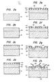
- Figures 2a - 2h are schematic flow diagrams of a semiconductor device which was formed by the use of the present invention.
- a transparent glass substrate 41 was prepared.
- an Si thin layer 42 having a thickness of 500 ⁇ to several ⁇ m is formed on the substrate 41, by heating a first evaporation source (an Si bar) with an electron beam by the ultra-high vacuum evaporation apparatus described before.
- a first evaporation source an Si bar
- the Si thin layer becomes polycrystalline.
- An Si molecular beam vaporised from the molecular beam source employing an electron gun is deposited within the ultra-high vacuum atmosphere which has a base vacuum degree of at most 10 -9 Torr.
- the substrate 41 is held at 500 o C (usually, at 400 - 650°C).
- a doping source for the impurity doping is packed in another crucible and is heated for the doping separately from the Si source.
- an Si0 2 film 43 is vacuum-evaporated on the Si thin layer 42 in the ultra-high vacuum atmosphere.
- the oxide film 43 suffices with a thickness of about 0.3 pm.
- a Mo film 44 is formed on the oxide film 43 by vacuum evaporation within the ultra-high vacuum atmosphere.
- a Mo piece is inserted in a crucible in advance. It is melted by a heating method utilizing induction heating, an electron beam or the like. Further, high-melting metals such as N i, W, Ti, Cr, Pd and Pt can be similarly used. Of course, metal elements or alloys of comparatively low melting points, such as Au and Al, may be similarly employed. In this case, the crucible may be at a comparatively low temperature, e.g. heated by electric resistance heating.
- the films of the semiconductor, insulator and metal which have properties different from one another are successively stacked on the glass substrate, whereupon the resultant structure is taken out of the ultra-high vacuum vessel so as to form a semiconductor device by the conventional semiconductor element-producing technology.
- windows 45 for diffusing a conductivity type impurity are formed in the Mo film 44, and windows 46 are subsequently formed in the oxide film 43 by utilizing the windows 45.
- the metal film 44 serves as an implantation mask, and hence, the oxide film 43 may well remain in the implantation windows.
- diffusion windows 46 extending down to the Si film 42 are, of course, used.
- diffusion regions 47. of a p-conductivity type impurity are formed in the Si thin layer 42 through the implantation windows.
- boron is turned into cations, which are implanted at an acceleration voltage of 200 keV and at a dose of about 3 x 10 15 /cm 2 .
- the resultant structure is annealed at 500°C for about 1 hour, to complete the conductive regions.
- the conductive regions may be similarly formed by conventional thermal diffusion.
- the conductive regions 47 formed function as the source and drain regions of the MOS transistor.
- metal electrodes 48 of Al are formed by conventional vacuum evaporation or the like as shown in Figure 2h. External,lead wires are connected to the metal electrodes. Then, the MOS transistor is completed.
- the device is depicted as a discrete component element provided with lead wires, it is needless to say that in the case of an IC etc., the electrodes are connected by stripe-shaped metal films.
- a gate oxide film 431 formed by this method is very clean, and the transistor manufactured by the above steps exhibits good characteristics. This is because, during the ion implantation, the metal film 44 prevents the ions from being introduced into the oxide film 43. Such effect does not depend upon the sort of the metal. Similar effects are achieved even with the various metals mentioned previously. Owing to the effect, no defect which gives rise to a surface state which lowers the mobility of the transistor is observed in the gate oxide film 431. Thus, the mobility of the polycrystalline silicon film-transistor has been improved by a factor of two or more. Naturally, the prior-art step of removing contaminated oxide films together after the ion implantation is dispensed with, so that the process for forming a device is remarkably simplified.
- the metal film 44 can be used as an electrode as it is, and this point is greatly advantageous in the process.
- the present invention is very effective for preventing a predetermined region such as a channel region from being contaminated due to the impurity doping.
- the example described above in detail has a great industrial merit in that in forming multilayer films by continuously evaporating a semiconductor film, insulating film, metal film etc. on a predetermined substrate within an ultra-high vacuum vessel, the interfaces of the films can be made clean.
- Si has been exemplified as a semiconductor material.
- other semiconductor materials for example, Ge or a compound semiconductor such as GaAs and GaAlAs are used, quite similar effects are achieved. That is, the interfaces of the layers of the various materials are very good.
- an impurity is ion-implanted into a material layer underlying a metal layer through an opening provided in the metal layer, there is the advantage that the impurity can be introduced locally into the part corresponding to the opening, without being mixed into unnecessary parts.
Landscapes
- Chemical & Material Sciences (AREA)
- Chemical Kinetics & Catalysis (AREA)
- Engineering & Computer Science (AREA)
- Materials Engineering (AREA)
- Mechanical Engineering (AREA)
- Metallurgy (AREA)
- Organic Chemistry (AREA)
- Physical Deposition Of Substances That Are Components Of Semiconductor Devices (AREA)
- Electrodes Of Semiconductors (AREA)
Abstract
Description
- This invention relates to a method of manufacturing a semiconductor device employing evaporation under ultra-high vacuum (usually called "molecular-beam epitaxy process" - abbreviated to MBE process).
- In recent years, the technique has progressed in which semiconductor films are formed on a crystal substrate, or alternatively on an amorphous substrate of glass or the like or a polycrystalline substrate, using the MBE process. Semiconductor devices employing the semiconductor films have been developed.
- With this technique, however, there has been the difficulty that when such semiconductor layer formed under an ultra-high vacuum subsequently has, e.g. an insulator layer formed thereon under conditions other than ultra-high vacuum, a surface state appears in the interface between the semiconductor layer and the insulator layer on account of, e.g. an impurity taken into the insulator layer, so the mobility of the carriers is lowered.
- Further, a similar difficulty is involved when forming a metal film on an insulator layer.
- Molecular beam epitaxy has been reported in detail in, for example, "Progress in Solid-State Chemistry", Vol. 10, Part 3, pp. 157-191, Pergamon Press 1975.
- In reports made up to now, the advantage of the MBE process has not been fully exploited as described above.
- The present invention provides a method of manufacturing a semiconductor device, including the step of evacuating a vacuum vessel to an ultra-high vacuum, the vessel containing a first evaporation source and a substrate having a surface onto which a layer is to be evaporated; and the step of forming a first evaporation layer on said surface using the first evaporation source; characterised in that the vacuum vessel contains at least a second evaporation source, and the method includes the step of subsequently forming a second evaporation layer on the first evaporation layer, using the second evaporation source, without removing the substrate from the vacuum vessel between the formation of the first and second evaporation layers.
- One of the evaporation sources can be a semiconductor material and another an insulator material. Suitably the pressure of the vacuum is at most 10 Torr. Of course, further substances can be evaporated into multilayer films as may be needed.
- By employing a glass substrate, a ceramic substrate or the like as the aforecited substrate, a large area is readily attained. When employing a single-crystal substrate, the size of the semiconductor device is limited first by the size of the substrate. A silicon substrate is limited to a size of approximately 75 mm x 75 mm.
- Since the present invention, at least in the preferred example, forms multilayer films consecutively within the same vessel, the films do not touch the outside air containing many contamination sources, and hence, not only the formed films themselves but also the interfaces of the respective films are kept clean. For this reason, the multilayer films obtained are free from the occurrence of a surface state, are very stable without fluctuations and exhibit good characteristics. More specifically, it is a matter of course that when adsorbed in a film to be'formed, residual gases such as the air degrade the characteristics of the film. Even when a film has been formed clean, once the film is exposed to the outside air or the like, various kinds of molecules contained in the atmosphere adhere to the surface thereof. When a further film is formed with the molecules left adherent, these molecules degrade the respective films directly or indirectly. When the multilayer films which have been formed bearing the impure molecules etc. in this manner are used in a device, they have evil effects on the electr.ical characteristics of the device such as the threshold voltage and the breakdown voltage or on the design and control of the device. With our preferred multilayer films, factors allowing such degradation are fully eliminated, and good multilayer films can be formed without any such problems.
- Such multilayer films are very effective when utilised for the formation of a semiconductor device, especially a semiconductor element sensitive to the surface state, such as MOSFET (MOS type Field Effect Transistor).
- Owing to the interaction between a semiconductor (e.g. Si) molecular beam which comes flying within the ultra-high vacuum, and the surface of a glass substrate, adsorbed Si molecules grow as an Si film of high purity which imbibes residual gases little. By virtue of the clean atmosphere of the ultra-high vacuum, the silicon which has reached the surface of the glass substrate has its thermal motion hindered little by foreign. molecules (residual gases etc.). Accordingly, it becomes a thermodynamically stable crystal phase even at a low temperature. Where the atmosphere of the vacuum vessel exceeds 10-9 Torr, its reactions with the residual gases become intense to rapidly lower the purity of the film and to hinder the thermal motion of the silicon on the substrate, so that the crystallisation becomes difficult. In the case of an ultra-high vacuum whose pressure is at most 10 9 Torr, the mean free path is several km to several hundred km, and the scattering molecules are not hindered by the foreign residual gas molecules or impurity atoms, so that they are grown on the glass as a crystal. In addition, where the substrate is below room temperature, kinetic energy required for the crystallisation is insufficient, and the growth of a crystal film of good quality is not attained. Where the softening point of the substrate glass is exceeded, the substrate is melted or transformed, so that the crystal film is not grown.
- The glass substrate is not a crystalline body, but it is usually a non-crystalline body (amorphous or vitreous). In the ultra-high vacuum atmosphere,. however, the film to be formed on the glass substrate has the property of becoming a crystal layer as stated before.
- The degree of vacuum during the evaporation is suitably below 1 x 10⁻⁸ Torr in terms of pressure, and the partial pressure of oxygen is below 1 x 10⁻⁹ Torr.
- On the semiconductor film formed, an insulating film is formed within the aforecited ultra-high vacuum. Since the insulating film is ordinarily a compound such as SiO2, Si3N4 and A1203, a method of evaporation as described below may be adopted. For example, in case of Al2O3, an Al molecular beam is generated from a cell disposed by the side of a vaporisation source for Si and is let fly onto the Si film in an oxygen.atmosphere. In general, in order to facilitate the formation of A1203, the Si film has light or an electron beam directed thereon or is irradiated with nascent oxygen. Where the evaporation source is of low melting point, the molecular beam-generating vessel may well be a vessel in the shape of a crucible round which a resistive heater is wound. In the case of a high melting point, a vessel which is capable of electron-beam heating, induction heating or the like is used. When the evaporation film is to be varied, a shutter or the like is adjusted, whereby the insulating film can be readily formed on the semiconductor film.
- Where a metal film is to be formed on the semiconductor film, it is quite similarly formed within the aforecited ultra-high vacuum. A metal element of high melting point such as Mo, Ta, Pd, Pt, W and Ti is evaporated by putting it into a metal molecular beam likewise to the case of the semiconductor. In the case of a metal compound, it is important to independently evaporate the constituents of the compound from individual cells as in the case of the insulating film. This is because the vapor pressures of the respective elements constituting the compound are unequal.
- In this manner, the present invention preferably consists in evaporating films by irradiating a substrate at a low temper.ature with the molecular beam of the respective evaporation sources within ultra-high vacuum. Therefore, even when the evaporation sources include materials of quite different natures such as a semiconductor, insulator and metal, the films can be continuously and successively grown without possessing any foreign molecule or residual gas exerting an adverse effect, in the interfaces and the materials. Various means can be used to generate the molecular beam, including the foregoing methods using an electron beam and r. f. heating, and methods using a laser beam or a plasma exhibit quite similar effects.
- An example of the method of this invention will now be described in detail, with reference to the accompanying drawings, wherein:
- Figure 1 is a view for explaining the outline of an ultra-high vacuum evaporation apparatus, and
- Figures 2a to 2h are partial sectional views showing the manufacturing steps of a semiconductor device.
- As illustrated in Figure 1, a vacuum vessel 11 is held under an ultra-high vacuum condition with a pressure of at most 10 Torr. The fore end part (surface part) of a Si source l24 is held in a melted state by an
electron beam 123 emitted from an E (Electron) gun-system 122, and a molecular beam of Si is generated. Theelectron beam 123 is deflected by an external magnetic field so as to collide against theSi source 124. With the molecular beam, an Si film can be epitaxially grown on aglass substrate 13 at a rate of 1 - 100 Å/second. The Si grows up on thesubstrate 13 to a film thickness of 500 Å to several pm under a polycrystalline state. Subsequently, an insulating film is formed on the Si film. In the case of depositing, for example, an oxide film as the insulating film, avaporization source 12 is used to form a molecular beam of Sio2 by way of example so as to deposit the Si02 on the polycrystalline film. The vaporised Si02 molecules .reach theglass substrate 13 through anaperture 141 which is provided in ashroud 14.Vaporisation sources 12',12" and 121 are used as are needed for the compositions of films to be formed. - By adopting the above MBE process, several advantages can be achieved. It is possible to obtain various information whilst forming a thin film and to feed it back to control the growth of the film. First, the clean state of the
substrate 13 before the growth or the surface structure of the grown layer can be immediately known by the use of an RHEED (Reflection High Energy Electron Diffraction) device which consists of anelectron gun 15 and afluorescent screen 16 as well as acontroller 17 thereof, these being mounted on predetermined positions of the vacuum vessel 11. In addition, amass spectrometer 18 which is placed in opposition to thevaporisation source 12 or 124 (and if necessary, to thesources 12',12" and 121) measures the kinds and quantities of residual gases and the quantities of respective constituent elements given forth from the vaporisation sources 12,124 etc. This information is inputted to acomputer 19 for process control. The growth rate, the thickness of the film, the composition ratio of a mixed crystal and the impurity concentration which have been calculated by the computer are immediately displayed on a cathode-ray tube 191 and plotted on arecorder 192. Simultaneously therewith, they are fed back to the temperature control of a molecular-beam generator vessel (vaporization source oven). In the illustrated example, thevaporization source 121 is connected to thecomputer controller 19. The crystal growth is entirely programmed, and films of a multilayer structure are formed. In the vapor growth or liquid growth which is.presently used as the epitaxial growth process of semiconductor films, only the temperature is obtained as an information during the crystal growth. In this connection, it is possible to say that MBE is a film growing method which is really rich in controllability. Regarding the epitaxial growth of a compound semiconductor such as GaAs, since the vapor pressures of the constituent elements are remarkably different, obtaining of the compound at the stoichiometric ratio is difficult merely by vaporising a GaAs bulk or the like material as it is. In this regard, a compound at the predetermined stoichiometric ratio is obtained by the so-called three- temperature method in which the elements of the composition are vaporised from individual vaporisation sources and in which the component of the higher vapor pressure is supplied in excess. Also in this case, since the interior of the evaporation chamber is under ultra-high vacuum, a crystal at the stoichiometric ratio can be grown merely by causing the beams of the constituent elements of the different vapor pressures to reach the substrate. - The superiority of the present invention has been proved in the following manner.
- Four glass plates A, B, C and D whose surfaces were flat and smooth were prepared. Polycrystalline silicon films 5,000 Å thick were formed on the respective glass substrates by the MBE method. Subsequently, only the glass plate B was formed with an Si02 film of a thickness of 2,000 Å by the MBE method (Sample B). Thereafter, the glass plates A - D were drawn out of the vacuum vessel. On the polycrystalline Si film of the glass plate C, an Si02 film 0 2,000 A thick was formed by the MBE method again (Sample C). On the other hand, an SiO2 film 100 Å thick was formed on the polycrystalline Si film of the glass plate D by the chemical vapor deposition (CVD) process (Sample D). Using the respective samples B - D, MOS type FETs were formed, and the mobilities p were measured. The glass plate A formed with only the polycrystalline Si film was Sample A for reference.
- Table 1 lists the results.

- Figures 2a - 2h are schematic flow diagrams of a semiconductor device which was formed by the use of the present invention.
- As shown in Figure 2a, a
transparent glass substrate 41 was prepared. Subsequently, as shown in Figure 2b, an Sithin layer 42 having a thickness of 500 Å to several µm is formed on thesubstrate 41, by heating a first evaporation source (an Si bar) with an electron beam by the ultra-high vacuum evaporation apparatus described before. Usually, the Si thin layer becomes polycrystalline. An Si molecular beam vaporised from the molecular beam source employing an electron gun is deposited within the ultra-high vacuum atmosphere which has a base vacuum degree of at most 10-9 Torr. In this case, thesubstrate 41 is held at 500oC (usually, at 400 - 650°C). In forming the Sithin layer 42, a molecular beam of an impurity controlled to be n-conductivity type or p-conductivity type, for example Sb or Ga, is evaporated simultaneously with the Si. Usually, a doping source for the impurity doping is packed in another crucible and is heated for the doping separately from the Si source. Subsequently, as shown in Figure 2c, an Si02 film 43 is vacuum-evaporated on the Sithin layer 42 in the ultra-high vacuum atmosphere. Theoxide film 43 suffices with a thickness of about 0.3 pm. Subsequently, as shown in Figure 2d, aMo film 44 is formed on theoxide film 43 by vacuum evaporation within the ultra-high vacuum atmosphere. As the evaporation source of the Mo film, a Mo piece is inserted in a crucible in advance. It is melted by a heating method utilizing induction heating, an electron beam or the like. Further, high-melting metals such as Ni, W, Ti, Cr, Pd and Pt can be similarly used. Of course, metal elements or alloys of comparatively low melting points, such as Au and Al, may be similarly employed. In this case, the crucible may be at a comparatively low temperature, e.g. heated by electric resistance heating. - In this manner, the films of the semiconductor, insulator and metal which have properties different from one another are successively stacked on the glass substrate, whereupon the resultant structure is taken out of the ultra-high vacuum vessel so as to form a semiconductor device by the conventional semiconductor element-producing technology. More specifically, as shown in Figure 2e and Figure 2f, using the known lithography technique,
windows 45 for diffusing a conductivity type impurity are formed in theMo film 44, andwindows 46 are subsequently formed in theoxide film 43 by utilizing thewindows 45. When employing ion implantation for the introduction of an impurity, themetal film 44 serves as an implantation mask, and hence, theoxide film 43 may well remain in the implantation windows. When employing thermal diffusion,diffusion windows 46 extending down to theSi film 42 are, of course, used. At the next step, as shown in Figure 2g,diffusion regions 47. of a p-conductivity type impurity are formed in the Sithin layer 42 through the implantation windows. As to the conditions of the ion implantation, by way of example, boron is turned into cations, which are implanted at an acceleration voltage of 200 keV and at a dose of about 3 x 10¹⁵/cm2. After the ion implantation, the resultant structure is annealed at 500°C for about 1 hour, to complete the conductive regions. Of course, the conductive regions may be similarly formed by conventional thermal diffusion. Theconductive regions 47 formed function as the source and drain regions of the MOS transistor. After the unnecessary parts of themetal film 44 have been removed,metal electrodes 48 of Al are formed by conventional vacuum evaporation or the like as shown in Figure 2h. External,lead wires are connected to the metal electrodes. Then, the MOS transistor is completed. Although, in the Figure, the device is depicted as a discrete component element provided with lead wires, it is needless to say that in the case of an IC etc., the electrodes are connected by stripe-shaped metal films. - A
gate oxide film 431 formed by this method is very clean, and the transistor manufactured by the above steps exhibits good characteristics. This is because, during the ion implantation, themetal film 44 prevents the ions from being introduced into theoxide film 43. Such effect does not depend upon the sort of the metal. Similar effects are achieved even with the various metals mentioned previously. Owing to the effect, no defect which gives rise to a surface state which lowers the mobility of the transistor is observed in thegate oxide film 431. Thus, the mobility of the polycrystalline silicon film-transistor has been improved by a factor of two or more. Naturally, the prior-art step of removing contaminated oxide films together after the ion implantation is dispensed with, so that the process for forming a device is remarkably simplified. Furthermore, themetal film 44 can be used as an electrode as it is, and this point is greatly advantageous in the process. In this manner, where the ion implantation step of doping a semiconductor with a high level of impurity atoms is used and where a metal mask is required, the present invention is very effective for preventing a predetermined region such as a channel region from being contaminated due to the impurity doping. - The example described above in detail has a great industrial merit in that in forming multilayer films by continuously evaporating a semiconductor film, insulating film, metal film etc. on a predetermined substrate within an ultra-high vacuum vessel, the interfaces of the films can be made clean.
- While only the manufacture of a MOSFET has been referred to in the foregoing embodiment, one skilled in the art will be able to readily conjecture that the present invention is easily applicable to any other active or passive element or an element having a plurality of thin layers such as multilayer interconnection layers and passivation layers.
- In the above embodiment, Si has been exemplified as a semiconductor material. Even when other semiconductor materials, for example, Ge or a compound semiconductor such as GaAs and GaAlAs are used, quite similar effects are achieved. That is, the interfaces of the layers of the various materials are very good. In addition, where an impurity is ion-implanted into a material layer underlying a metal layer through an opening provided in the metal layer, there is the advantage that the impurity can be introduced locally into the part corresponding to the opening, without being mixed into unnecessary parts.
Claims (7)
Applications Claiming Priority (2)
| Application Number | Priority Date | Filing Date | Title |
|---|---|---|---|
| JP6395/81 | 1981-01-21 | ||
| JP56006395A JPS57121219A (en) | 1981-01-21 | 1981-01-21 | Manufacture of semiconductor device |
Publications (2)
| Publication Number | Publication Date |
|---|---|
| EP0056737A2 true EP0056737A2 (en) | 1982-07-28 |
| EP0056737A3 EP0056737A3 (en) | 1983-06-29 |
Family
ID=11637174
Family Applications (1)
| Application Number | Title | Priority Date | Filing Date |
|---|---|---|---|
| EP82300288A Withdrawn EP0056737A3 (en) | 1981-01-21 | 1982-01-20 | Method of manufacturing a semiconductor device using molecular beam epitaxy |
Country Status (3)
| Country | Link |
|---|---|
| EP (1) | EP0056737A3 (en) |
| JP (1) | JPS57121219A (en) |
| CA (1) | CA1184020A (en) |
Cited By (4)
| Publication number | Priority date | Publication date | Assignee | Title |
|---|---|---|---|---|
| EP0113983A1 (en) * | 1982-12-16 | 1984-07-25 | Fujitsu Limited | Fabricating a semiconductor device by means of molecular beam epitaxy |
| US4477311A (en) * | 1982-12-28 | 1984-10-16 | Fujitsu Limited | Process and apparatus for fabricating a semiconductor device |
| EP0127838A3 (en) * | 1983-06-06 | 1987-05-20 | International Business Machines Corporation | Silicon sources suitable for use in molecular beam epitaxy deposition |
| WO2016201526A1 (en) * | 2015-06-19 | 2016-12-22 | Chee Yee Kwok | Silicon film and process for forming silicon film |
Families Citing this family (1)
| Publication number | Priority date | Publication date | Assignee | Title |
|---|---|---|---|---|
| JPH02172226A (en) * | 1988-12-23 | 1990-07-03 | Nec Corp | Method and apparatus for forming silicon oxide film |
Family Cites Families (2)
| Publication number | Priority date | Publication date | Assignee | Title |
|---|---|---|---|---|
| US3928092A (en) * | 1974-08-28 | 1975-12-23 | Bell Telephone Labor Inc | Simultaneous molecular beam deposition of monocrystalline and polycrystalline III(a)-V(a) compounds to produce semiconductor devices |
| JPS5391573A (en) * | 1977-01-21 | 1978-08-11 | Mitsubishi Electric Corp | Molecular-beam epitaxial growth equipment |
-
1981
- 1981-01-21 JP JP56006395A patent/JPS57121219A/en active Pending
-
1982
- 1982-01-20 EP EP82300288A patent/EP0056737A3/en not_active Withdrawn
- 1982-01-20 CA CA000394515A patent/CA1184020A/en not_active Expired
Cited By (5)
| Publication number | Priority date | Publication date | Assignee | Title |
|---|---|---|---|---|
| EP0113983A1 (en) * | 1982-12-16 | 1984-07-25 | Fujitsu Limited | Fabricating a semiconductor device by means of molecular beam epitaxy |
| EP0208851A1 (en) * | 1982-12-16 | 1987-01-21 | Fujitsu Limited | Fabricating a semiconductor device by means of molecular beam epitaxy |
| US4477311A (en) * | 1982-12-28 | 1984-10-16 | Fujitsu Limited | Process and apparatus for fabricating a semiconductor device |
| EP0127838A3 (en) * | 1983-06-06 | 1987-05-20 | International Business Machines Corporation | Silicon sources suitable for use in molecular beam epitaxy deposition |
| WO2016201526A1 (en) * | 2015-06-19 | 2016-12-22 | Chee Yee Kwok | Silicon film and process for forming silicon film |
Also Published As
| Publication number | Publication date |
|---|---|
| CA1184020A (en) | 1985-03-19 |
| JPS57121219A (en) | 1982-07-28 |
| EP0056737A3 (en) | 1983-06-29 |
Similar Documents
| Publication | Publication Date | Title |
|---|---|---|
| US4800100A (en) | Combined ion and molecular beam apparatus and method for depositing materials | |
| US4888202A (en) | Method of manufacturing thin compound oxide film and apparatus for manufacturing thin oxide film | |
| US6080643A (en) | Elimination of dehydrogenation step when forming a silicon thin film device by low-temperature laser-annealing | |
| DE69229265T2 (en) | METHOD FOR PRODUCING AND DOPING HIGHLY INSULATING THIN LAYERS FROM MONOCRISTALLINE GALLIUM NITRIDE | |
| KR20190024675A (en) | Method for fabricating metal chalcogenide thin films | |
| US3992233A (en) | Surface treatment of III-V compound crystals | |
| KR100229698B1 (en) | Method and apparatus for forming an soi substrate by use of a plasma irradiation | |
| EP0055032B1 (en) | Field effect transistors | |
| CA1184020A (en) | Method of manufacturing semiconductor device | |
| GB1602386A (en) | Method of manufacturing semiconductor devices | |
| US7492086B1 (en) | Low work function emitters and method for production of FED's | |
| US4233613A (en) | Compound semiconductor wafer | |
| US4698235A (en) | Siting a film onto a substrate including electron-beam evaporation | |
| EP0215436B1 (en) | Method of growth of thin film layer for use in a composite semiconductor | |
| US20030151051A1 (en) | High performance active and passive structures based on silicon material grown epitaxially or bonded to silicon carbide substrate | |
| Feldman et al. | Mass spectra analyses of impurities and ion clusters in amorphous and crystalline silicon films | |
| Chow | Molecular beam epitaxy | |
| JPH0476217B2 (en) | ||
| EP0107325A2 (en) | Method of making oxide films | |
| JPS61174621A (en) | Manufacture of semiconductor thin crystal | |
| JP3392507B2 (en) | Small field emission cathode device | |
| US6368983B1 (en) | Multi-layer wafer fabrication | |
| JPS584920A (en) | Manufacture of semiconductor | |
| JPS583221A (en) | Ion beam accumulation | |
| JPH05259458A (en) | Manufacture of semiconductor device |
Legal Events
| Date | Code | Title | Description |
|---|---|---|---|
| PUAI | Public reference made under article 153(3) epc to a published international application that has entered the european phase |
Free format text: ORIGINAL CODE: 0009012 |
|
| 17P | Request for examination filed |
Effective date: 19820304 |
|
| AK | Designated contracting states |
Designated state(s): DE FR GB NL |
|
| PUAL | Search report despatched |
Free format text: ORIGINAL CODE: 0009013 |
|
| AK | Designated contracting states |
Designated state(s): DE FR GB NL |
|
| STAA | Information on the status of an ep patent application or granted ep patent |
Free format text: STATUS: THE APPLICATION IS DEEMED TO BE WITHDRAWN |
|
| 18D | Application deemed to be withdrawn |
Effective date: 19850720 |
|
| RIN1 | Information on inventor provided before grant (corrected) |
Inventor name: KOBAYASHI, KEISUKE L I Inventor name: MURAYAMA, YOSHIMASA Inventor name: MATSUI, MAKOTO Inventor name: SHIRAKI, YASUHIRO |