EP0056746A1 - Wärmetauscher mit Rohrbündel, versehen mit Ausdehnungswellen, die nicht von Vibrationen gestört werden - Google Patents
Wärmetauscher mit Rohrbündel, versehen mit Ausdehnungswellen, die nicht von Vibrationen gestört werden Download PDFInfo
- Publication number
- EP0056746A1 EP0056746A1 EP82400017A EP82400017A EP0056746A1 EP 0056746 A1 EP0056746 A1 EP 0056746A1 EP 82400017 A EP82400017 A EP 82400017A EP 82400017 A EP82400017 A EP 82400017A EP 0056746 A1 EP0056746 A1 EP 0056746A1
- Authority
- EP
- European Patent Office
- Prior art keywords
- lyres
- tubes
- expansion
- liquid
- expansion lyres
- Prior art date
- Legal status (The legal status is an assumption and is not a legal conclusion. Google has not performed a legal analysis and makes no representation as to the accuracy of the status listed.)
- Granted
Links
- 239000007788 liquid Substances 0.000 claims abstract description 34
- 239000012530 fluid Substances 0.000 claims abstract description 9
- 229910052751 metal Inorganic materials 0.000 claims description 5
- 239000002184 metal Substances 0.000 claims description 5
- 230000003068 static effect Effects 0.000 claims description 5
- 238000005452 bending Methods 0.000 claims description 4
- 230000006641 stabilisation Effects 0.000 claims description 3
- 238000011144 upstream manufacturing Methods 0.000 claims description 3
- 238000011105 stabilization Methods 0.000 claims description 2
- DGAQECJNVWCQMB-PUAWFVPOSA-M Ilexoside XXIX Chemical compound C[C@@H]1CC[C@@]2(CC[C@@]3(C(=CC[C@H]4[C@]3(CC[C@@H]5[C@@]4(CC[C@@H](C5(C)C)OS(=O)(=O)[O-])C)C)[C@@H]2[C@]1(C)O)C)C(=O)O[C@H]6[C@@H]([C@H]([C@@H]([C@H](O6)CO)O)O)O.[Na+] DGAQECJNVWCQMB-PUAWFVPOSA-M 0.000 abstract description 12
- 229910052708 sodium Inorganic materials 0.000 abstract description 12
- 239000011734 sodium Substances 0.000 abstract description 12
- XLYOFNOQVPJJNP-UHFFFAOYSA-N water Substances O XLYOFNOQVPJJNP-UHFFFAOYSA-N 0.000 description 5
- 229910052783 alkali metal Inorganic materials 0.000 description 3
- 150000001340 alkali metals Chemical class 0.000 description 3
- 210000002445 nipple Anatomy 0.000 description 2
- 241001080024 Telles Species 0.000 description 1
- 238000013459 approach Methods 0.000 description 1
- 230000005284 excitation Effects 0.000 description 1
- 230000002349 favourable effect Effects 0.000 description 1
- 229910001338 liquidmetal Inorganic materials 0.000 description 1
- 238000012986 modification Methods 0.000 description 1
- 230000004048 modification Effects 0.000 description 1
- 239000007921 spray Substances 0.000 description 1
Images


Classifications
-
- F—MECHANICAL ENGINEERING; LIGHTING; HEATING; WEAPONS; BLASTING
- F28—HEAT EXCHANGE IN GENERAL
- F28D—HEAT-EXCHANGE APPARATUS, NOT PROVIDED FOR IN ANOTHER SUBCLASS, IN WHICH THE HEAT-EXCHANGE MEDIA DO NOT COME INTO DIRECT CONTACT
- F28D7/00—Heat-exchange apparatus having stationary tubular conduit assemblies for both heat-exchange media, the media being in contact with different sides of a conduit wall
- F28D7/005—Heat-exchange apparatus having stationary tubular conduit assemblies for both heat-exchange media, the media being in contact with different sides of a conduit wall the conduits for only one medium being tubes having bent portions or being assembled from bent tubes or being tubes having a toroidal configuration
-
- F—MECHANICAL ENGINEERING; LIGHTING; HEATING; WEAPONS; BLASTING
- F28—HEAT EXCHANGE IN GENERAL
- F28D—HEAT-EXCHANGE APPARATUS, NOT PROVIDED FOR IN ANOTHER SUBCLASS, IN WHICH THE HEAT-EXCHANGE MEDIA DO NOT COME INTO DIRECT CONTACT
- F28D21/00—Heat-exchange apparatus not covered by any of the groups F28D1/00 - F28D20/00
- F28D2021/0019—Other heat exchangers for particular applications; Heat exchange systems not otherwise provided for
- F28D2021/0054—Other heat exchangers for particular applications; Heat exchange systems not otherwise provided for for nuclear applications
-
- F—MECHANICAL ENGINEERING; LIGHTING; HEATING; WEAPONS; BLASTING
- F28—HEAT EXCHANGE IN GENERAL
- F28F—DETAILS OF HEAT-EXCHANGE AND HEAT-TRANSFER APPARATUS, OF GENERAL APPLICATION
- F28F2265/00—Safety or protection arrangements; Arrangements for preventing malfunction
- F28F2265/26—Safety or protection arrangements; Arrangements for preventing malfunction for allowing differential expansion between elements
-
- Y—GENERAL TAGGING OF NEW TECHNOLOGICAL DEVELOPMENTS; GENERAL TAGGING OF CROSS-SECTIONAL TECHNOLOGIES SPANNING OVER SEVERAL SECTIONS OF THE IPC; TECHNICAL SUBJECTS COVERED BY FORMER USPC CROSS-REFERENCE ART COLLECTIONS [XRACs] AND DIGESTS
- Y10—TECHNICAL SUBJECTS COVERED BY FORMER USPC
- Y10S—TECHNICAL SUBJECTS COVERED BY FORMER USPC CROSS-REFERENCE ART COLLECTIONS [XRACs] AND DIGESTS
- Y10S165/00—Heat exchange
- Y10S165/051—Heat exchange having expansion and contraction relieving or absorbing means
- Y10S165/052—Heat exchange having expansion and contraction relieving or absorbing means for cylindrical heat exchanger
- Y10S165/063—Cylindrical heat exchanger fixed to fixed end supports
- Y10S165/065—Bent cylindrical heat exchanger
Definitions
- the present invention relates to a tube bundle device arranged between two tube plates and provided with expansion lyres, for heat exchange between a fluid circulating inside the tubes and a liquid circulating around the tubes.
- the expansion lyres of such devices can be driven in vibration for certain flow rates of the fluid circulating around the tubes, in particular when the latter is a liquid alkali metal. If the excitation frequency due to the flow of the fluid approaches the resonance frequency of the expansion lyres, vibrations may occur which are sufficient to seriously damage the tubes.
- the object of the present invention is to remedy the above drawbacks, and to provide a device which does not have a special zone reserved for expansion lyres and which does not participate in the heat exchange. It also aims to ensure the operation of the expansion lyres with a more favorable working rate, outside the hottest part of the exchanger, and consequently to use tubes of smaller thickness.
- a heat exchange device comprising an external shell closed at its ends by two tube plates, a bundle of tubes fitted with expansion lyres, these tubes being connected to the tube plates to lead into the inlet and outlet manifolds of a fluid circulating inside the tubes and inlet pipes and outlet of a liquid circulating in said ferrule and around the tubes, characterized in that the expansion lyres are arranged in contact with the liquid in the coldest zone of the exchanger and in that means are provided for deflecting at least part of the liquid flow at the expansion lyres so that the liquid cannot cause the latter to vibrate.
- the means for deflecting at least part of the liquid flow rate include an inner jacket to the outer shell and in which the lyres are placed. expansion and at least one orifice formed in said shell upstream of the expansion lyres to divert at least part of the flow of liquid between the inner jacket and the outer shell.
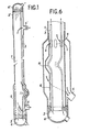
- the steam generator has an outer shroud 1, with a vertical axis, closed at its lower and upper ends by tube plates 2,2 ′ to which the tubes such as 3 of a bundle of tubes arranged inside of the shell 1.
- These tubes open respectively, at the lower part of the steam generator, into an inlet manifold 4 for the water of the secondary circuit of the generator and at its upper part, into an outlet manifold 4 'of the water spray.
- the water to be vaporized therefore circulates from bottom to top inside the tubes 3 between the collectors 4 and 4 '.
- the liquid metal (generally sodium) circulating in the primary circuit of the generator moves against the current with respect to the water in the primary circuit, that is to say from top to bottom, inside the shell. 1 and around the tubes 3 between an inlet pipe 5 'and an outlet pipe 5.
- the tubes 3 are generally rectilinear and each define a vertical axis X. However, they each have, near their lower end connected to the tube plate 2, a dilatation lyre shown at 11 in its cold position and 12 in its hot position.
- the expansion lyres are thus in the coldest area of the exchanger, that is to say in contact with the liquid sodium, cooled in contact with the water to be vaporized.
- the expansion lyres are balanced, that is to say that the length of their branches and their position relative to the axes X of the tubes are such that the lyres exert in operation no bending reaction on the teats. 13A for joining the tubes with the tube plate 2.
- the expansion lyres 11 are arranged inside a thin jacket 6 which defines with the external ferrule 1 an annular passage through which is deflected at least part of the flow rate of the liquid sodium circulating between the ferrules inlet 5 'and outlet 5.
- the thin jacket 6 comprises above the expansion lyres 11 an annular orifice 8 through which at least part of the liquid sodium descending into the shell 1 is deflected in the annular passage formed between this ferrule and the jacket 6.
- the shell 6 extends below the expansion lyres by a perforated shell 7 welded to the shell and by which the part of the liquid sodium descending inside the shell 6 comes out in the annular passage to be discharged through the tubing 5 with the part of the sodium which has been deflected in this passage through the orifice 8.
- This perforated ferrule 7 ensures the desired distribution of the flow of liquid sodium between the internal and external zones of the jacket 6 More specifically, the passage section of the holes of the perforated shell 7 defines a sufficiently large pressure drop, relative to the passage section around the jacket 6, so that the flow of hot liquid sodium inside of the shirt is low enough not to risk causing vibrations of the lyres, expansion.
- the perforated ferrule 7 is fixed to a circular crown 9, itself connected to the tube plate 2 by bolts 10.
- FIG. 3 represents a variant of the steam generator of FIG. 2 in which the expansion lyres such as 13 are symmetrical with respect to the general axis X of the corresponding tube (the position of the hot lyre is represented at 14).
- This has the advantage of reducing the transverse size of the lyres and therefore the diameter of the ferrule 6.
- the length of the lyres is increased and they exert in operation a certain bending force on the corresponding teats of the junction of the tube with the tube plate (not shown).
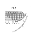
- Figure 4 is a sectional view along the axis IV-IV of Figure 2 and Figure 5 a detail view V of Figure 4. These figures show the staggered distribution of the tubes such as 13, 14, 15, 16, and the bars such as 17, 18 , 19 slid between the rows of tubes to increase safety vis-à-vis their vibrations.
- FIG. 6 a variant of FIG. 2 according to which the area internal to the shell 6 containing the expansion lyres 11 contains liquid sodium in the static state and not in circulation.
- the perforated shell 7 is eliminated and the shell 6 is connected directly to the tube plate 2.
- the arrows illustrate in FIG. 6 the entire flow of liquid sodium s' made from the outside of the shell 6, through the orifices 8.
- the members for distributing the flow between the internal and external zones relative to the envelope may be other than a grid with calibrated holes. They can also be arranged upstream of the internal envelope, and no longer downstream of the latter.
- the invention applies to tube bundle heat exchangers with expansion lyres, in particular for a steam generator with a primary fluid consisting of a liquid alkali metal.
Landscapes
- Engineering & Computer Science (AREA)
- Physics & Mathematics (AREA)
- Thermal Sciences (AREA)
- Mechanical Engineering (AREA)
- General Engineering & Computer Science (AREA)
- Heat-Exchange Devices With Radiators And Conduit Assemblies (AREA)
- Details Of Heat-Exchange And Heat-Transfer (AREA)
Applications Claiming Priority (2)
| Application Number | Priority Date | Filing Date | Title |
|---|---|---|---|
| FR8100455A FR2497937B1 (fr) | 1981-01-13 | 1981-01-13 | Dispositif d'echange de chaleur a faisceau de tubes avec lyres de dilatation soustraites aux vibrations |
| FR8100455 | 1981-01-13 |
Publications (3)
| Publication Number | Publication Date |
|---|---|
| EP0056746A1 true EP0056746A1 (de) | 1982-07-28 |
| EP0056746B1 EP0056746B1 (de) | 1983-11-16 |
| EP0056746B2 EP0056746B2 (de) | 1988-03-16 |
Family
ID=9254059
Family Applications (1)
| Application Number | Title | Priority Date | Filing Date |
|---|---|---|---|
| EP82400017A Expired EP0056746B2 (de) | 1981-01-13 | 1982-01-07 | Wärmetauscher mit Rohrbündel, versehen mit Ausdehnungswellen, die nicht von Vibrationen gestört werden |
Country Status (6)
| Country | Link |
|---|---|
| US (1) | US4505329A (de) |
| EP (1) | EP0056746B2 (de) |
| JP (1) | JPS57136088A (de) |
| DE (1) | DE3260009D1 (de) |
| ES (1) | ES8401616A1 (de) |
| FR (1) | FR2497937B1 (de) |
Families Citing this family (11)
| Publication number | Priority date | Publication date | Assignee | Title |
|---|---|---|---|---|
| US4690206A (en) * | 1985-07-22 | 1987-09-01 | Westinghouse Electric Corp. | Nuclear steam generator wrapper barrel/tube support plate connection assembly and radial tuning method for assembling same |
| US4852640A (en) * | 1986-03-28 | 1989-08-01 | Exothermics-Eclipse Inc. | Recuperative heat exchanger |
| US7379555B2 (en) * | 1999-06-08 | 2008-05-27 | Insound Medical, Inc. | Precision micro-hole for extended life batteries |
| US7016504B1 (en) * | 1999-09-21 | 2006-03-21 | Insonus Medical, Inc. | Personal hearing evaluator |
| US6940989B1 (en) | 1999-12-30 | 2005-09-06 | Insound Medical, Inc. | Direct tympanic drive via a floating filament assembly |
| US6914994B1 (en) * | 2001-09-07 | 2005-07-05 | Insound Medical, Inc. | Canal hearing device with transparent mode |
| US20040069470A1 (en) * | 2002-09-10 | 2004-04-15 | Jacob Gorbulsky | Bent-tube heat exchanger |
| DE10352221A1 (de) * | 2003-11-08 | 2005-06-09 | Daimlerchrysler Ag | Wärmetauscher, insbesondere Abgaswärmetauscher |
| US20070003081A1 (en) * | 2005-06-30 | 2007-01-04 | Insound Medical, Inc. | Moisture resistant microphone |
| EP2177046B2 (de) * | 2007-08-14 | 2020-05-27 | Insound Medical, Inc | Kombinierte mikrophon- und empfängeranordnung für kanalhörgeräte mit längerer tragedauer |
| KR101608996B1 (ko) * | 2010-01-11 | 2016-04-05 | 엘지전자 주식회사 | 열 교환기 |
Citations (10)
| Publication number | Priority date | Publication date | Assignee | Title |
|---|---|---|---|---|
| FR1006491A (fr) * | 1948-01-22 | 1952-04-23 | Air Liquide | Procédé de construction des échangeurs de chaleur |
| FR2134067A1 (fr) * | 1970-03-06 | 1972-12-08 | Stein Industrie | Module echangeur de chaleur |
| FR2171869A2 (de) * | 1972-02-11 | 1973-09-28 | Stein Industrie | |
| FR2172799A1 (en) * | 1972-02-22 | 1973-10-05 | Trepaud Georges | Nuclear reactor heat exchanger - with central shaft giving access for tube installation and repair |
| FR2218528A1 (de) * | 1973-02-19 | 1974-09-13 | Stein Industrie | |
| FR2293684A2 (fr) * | 1974-12-05 | 1976-07-02 | Trepaud Georges | Echangeur de chaleur a faisceau tubulaire |
| FR2303257A1 (fr) * | 1975-03-03 | 1976-10-01 | Babcock & Wilcox Co | Echangeur de chaleur a faisceau des tubes longitudinalement alignes et mutuellement espaces par des deformations en helice menagees sur, au moins, une partie d'entre eux |
| DE2644303A1 (de) * | 1975-10-06 | 1977-04-14 | Neratoom | Verfahren zum ausbessern von waermetauschern |
| FR2415262A1 (fr) * | 1978-01-18 | 1979-08-17 | Commissariat Energie Atomique | Generateur de vapeur avec resurchauffeur integre alimente par un metal liquide |
| EP0004218A2 (de) * | 1978-03-07 | 1979-09-19 | COMMISSARIAT A L'ENERGIE ATOMIQUE Etablissement de Caractère Scientifique Technique et Industriel | Schneller Kernreaktor mit mindestens einem Hilfs-Wärmetauscher |
Family Cites Families (2)
| Publication number | Priority date | Publication date | Assignee | Title |
|---|---|---|---|---|
| FR1172799A (fr) * | 1957-03-04 | 1959-02-16 | Cfcmug | Procédé de mesure d'une puissance ou d'une énergie en courant continu et dispositifs faisant application de ce procédé |
| DE2224841A1 (de) * | 1971-05-26 | 1972-12-07 | Atomic Energy Authority Uk | Wärmetauscher |
-
1981
- 1981-01-13 FR FR8100455A patent/FR2497937B1/fr not_active Expired
-
1982
- 1982-01-07 US US06/337,759 patent/US4505329A/en not_active Expired - Fee Related
- 1982-01-07 DE DE8282400017T patent/DE3260009D1/de not_active Expired
- 1982-01-07 EP EP82400017A patent/EP0056746B2/de not_active Expired
- 1982-01-12 ES ES508651A patent/ES8401616A1/es not_active Expired
- 1982-01-12 JP JP57003243A patent/JPS57136088A/ja active Pending
Patent Citations (10)
| Publication number | Priority date | Publication date | Assignee | Title |
|---|---|---|---|---|
| FR1006491A (fr) * | 1948-01-22 | 1952-04-23 | Air Liquide | Procédé de construction des échangeurs de chaleur |
| FR2134067A1 (fr) * | 1970-03-06 | 1972-12-08 | Stein Industrie | Module echangeur de chaleur |
| FR2171869A2 (de) * | 1972-02-11 | 1973-09-28 | Stein Industrie | |
| FR2172799A1 (en) * | 1972-02-22 | 1973-10-05 | Trepaud Georges | Nuclear reactor heat exchanger - with central shaft giving access for tube installation and repair |
| FR2218528A1 (de) * | 1973-02-19 | 1974-09-13 | Stein Industrie | |
| FR2293684A2 (fr) * | 1974-12-05 | 1976-07-02 | Trepaud Georges | Echangeur de chaleur a faisceau tubulaire |
| FR2303257A1 (fr) * | 1975-03-03 | 1976-10-01 | Babcock & Wilcox Co | Echangeur de chaleur a faisceau des tubes longitudinalement alignes et mutuellement espaces par des deformations en helice menagees sur, au moins, une partie d'entre eux |
| DE2644303A1 (de) * | 1975-10-06 | 1977-04-14 | Neratoom | Verfahren zum ausbessern von waermetauschern |
| FR2415262A1 (fr) * | 1978-01-18 | 1979-08-17 | Commissariat Energie Atomique | Generateur de vapeur avec resurchauffeur integre alimente par un metal liquide |
| EP0004218A2 (de) * | 1978-03-07 | 1979-09-19 | COMMISSARIAT A L'ENERGIE ATOMIQUE Etablissement de Caractère Scientifique Technique et Industriel | Schneller Kernreaktor mit mindestens einem Hilfs-Wärmetauscher |
Also Published As
| Publication number | Publication date |
|---|---|
| FR2497937B1 (fr) | 1986-03-07 |
| JPS57136088A (en) | 1982-08-21 |
| DE3260009D1 (en) | 1983-12-22 |
| ES508651A0 (es) | 1983-12-16 |
| US4505329A (en) | 1985-03-19 |
| ES8401616A1 (es) | 1983-12-16 |
| EP0056746B2 (de) | 1988-03-16 |
| EP0056746B1 (de) | 1983-11-16 |
| FR2497937A1 (fr) | 1982-07-16 |
Similar Documents
| Publication | Publication Date | Title |
|---|---|---|
| EP0056746B1 (de) | Wärmetauscher mit Rohrbündel, versehen mit Ausdehnungswellen, die nicht von Vibrationen gestört werden | |
| FR2732452A1 (fr) | Echangeur de chaleur a plaques | |
| EP0161978B1 (de) | Schwingungsdämpfungsvorrichtung für die Befestigung eines Rohres dessen Wandstärke klein ist im Verhältnis zum Durchmesser | |
| EP0006795A1 (de) | Zwischenwärmeaustauscher für Kernreaktor mit schnellen Neutronen | |
| EP0057643B1 (de) | Schutzeinrichtung für die Rohrplatte an der heissen Seite eines vertikaler Wärmetauschers | |
| EP0246942A1 (de) | Rohrbündelwärmetauscher mit doppelwandigem Rohrboden | |
| CA1273546A (fr) | Dispositif de controle de debit dans un tube d'echangeur de chaleur | |
| EP0059662B1 (de) | Vorrichtung zum homogenen Vermischen fliessender Flüssigkeiten unterschiedlicher Temperaturen | |
| EP0041452B1 (de) | Vorrichtung zum Verringern der thermischen Spannung in Wärmetauschern | |
| EP0202967A1 (de) | Speisewasservorwärmer für Dampferzeuger | |
| FR2560664A1 (fr) | Manchon thermique pour raccordement entre un ajutage et un collecteur de surchauffeur ou un recipient sous pression | |
| BE1012445A3 (fr) | Dispositif pour refroidir un gaz porteur charge de vapeurs d'un produit. | |
| EP0082780B1 (de) | Dampferzeuger durch Wärmeaustauschung zwischen einem flüssigen, kalorienreichen Metall und Speisewasser | |
| EP0216667B1 (de) | Rückhaltevorrichtung für eine Flüssigkeit um zu verhindern, dass eine offene, im wesentlichen horizontale Leitung beim Unterschreiten einer bestimmten Zuflussmenge leer läuft | |
| EP0441697A1 (de) | Dampferzeuger mit Verteiler, insbesondere für Atomkraftwerk | |
| FR2889297A1 (fr) | Echangeur thermique, ensemble propulseur, et aeronef comportant un tel ensemble propulseur | |
| EP0462903B1 (de) | Röhren-Wärmetauscher für warme und kalte Fluide mit grossen Temperatur- und Druckunterschieden | |
| EP0112236B1 (de) | Verbindungsleitung zwischen zwei ortsfesten Geräten | |
| FR2761140A1 (fr) | Tete de lance pour nettoyer un generateur de vapeur | |
| FR2693309A1 (fr) | Procédé et dispositif d'évacuation de la puissance résiduelle d'un réacteur nucléaire à neurton rapides à l'arrêt. | |
| EP0348299B1 (de) | Wärmeaustauscher | |
| FR3088417A1 (fr) | Collecteur de fluide a coques multiples pour echangeur de chaleur avec circulation du fluide collecte entre les coques | |
| BE658443A (de) | ||
| FR2754331A1 (fr) | Outil destine au nettoyage par jets d'eau sous haute pression, notamment nettoyage d'une plaque tubulaire de generateur de vapeur | |
| BE893169A (fr) | Dispositif de recuperation de chaleur d'une chaudiere pour chauffage central |
Legal Events
| Date | Code | Title | Description |
|---|---|---|---|
| PUAI | Public reference made under article 153(3) epc to a published international application that has entered the european phase |
Free format text: ORIGINAL CODE: 0009012 |
|
| AK | Designated contracting states |
Designated state(s): BE CH DE GB IT NL |
|
| 17P | Request for examination filed |
Effective date: 19821202 |
|
| ITF | It: translation for a ep patent filed | ||
| GRAA | (expected) grant |
Free format text: ORIGINAL CODE: 0009210 |
|
| AK | Designated contracting states |
Designated state(s): BE CH DE GB IT LI NL |
|
| REF | Corresponds to: |
Ref document number: 3260009 Country of ref document: DE Date of ref document: 19831222 |
|
| PGFP | Annual fee paid to national office [announced via postgrant information from national office to epo] |
Ref country code: CH Payment date: 19840112 Year of fee payment: 3 |
|
| PLBI | Opposition filed |
Free format text: ORIGINAL CODE: 0009260 |
|
| 26 | Opposition filed |
Opponent name: GEBRUEDER SULZER AKTIENGESELLSCHAFT Effective date: 19840816 |
|
| RAP2 | Party data changed (patent owner data changed or rights of a patent transferred) |
Owner name: COMMISSARIAT A L'ENERGIE ATOMIQUE Owner name: STEIN INDUSTRIE SOCIETE ANONYME DITE: |
|
| PUAH | Patent maintained in amended form |
Free format text: ORIGINAL CODE: 0009272 |
|
| STAA | Information on the status of an ep patent application or granted ep patent |
Free format text: STATUS: PATENT MAINTAINED AS AMENDED |
|
| PG25 | Lapsed in a contracting state [announced via postgrant information from national office to epo] |
Ref country code: LI Effective date: 19880131 Ref country code: CH Effective date: 19880131 |
|
| 27A | Patent maintained in amended form |
Effective date: 19880316 |
|
| AK | Designated contracting states |
Kind code of ref document: B2 Designated state(s): BE CH DE GB IT NL |
|
| NLR2 | Nl: decision of opposition | ||
| NLR3 | Nl: receipt of modified translations in the netherlands language after an opposition procedure | ||
| ITF | It: translation for a ep patent filed | ||
| NLS | Nl: assignments of ep-patents |
Owner name: SOCIETE ANONYME DITE: STEIN INDUSTRIE TE VELIZY-VI |
|
| REG | Reference to a national code |
Ref country code: CH Ref legal event code: PL |
|
| PGFP | Annual fee paid to national office [announced via postgrant information from national office to epo] |
Ref country code: BE Payment date: 19901219 Year of fee payment: 10 |
|
| PGFP | Annual fee paid to national office [announced via postgrant information from national office to epo] |
Ref country code: DE Payment date: 19901222 Year of fee payment: 10 |
|
| PGFP | Annual fee paid to national office [announced via postgrant information from national office to epo] |
Ref country code: GB Payment date: 19910103 Year of fee payment: 10 |
|
| ITTA | It: last paid annual fee | ||
| PGFP | Annual fee paid to national office [announced via postgrant information from national office to epo] |
Ref country code: NL Payment date: 19910131 Year of fee payment: 10 |
|
| PG25 | Lapsed in a contracting state [announced via postgrant information from national office to epo] |
Ref country code: GB Effective date: 19920107 |
|
| PG25 | Lapsed in a contracting state [announced via postgrant information from national office to epo] |
Ref country code: BE Effective date: 19920131 |
|
| BERE | Be: lapsed |
Owner name: COMMISSARIAT A L'ENERGIE ATOMIQUE Effective date: 19920131 Owner name: STEIN INDUSTRIE Effective date: 19920131 |
|
| PG25 | Lapsed in a contracting state [announced via postgrant information from national office to epo] |
Ref country code: NL Effective date: 19920801 |
|
| GBPC | Gb: european patent ceased through non-payment of renewal fee | ||
| NLV4 | Nl: lapsed or anulled due to non-payment of the annual fee | ||
| PG25 | Lapsed in a contracting state [announced via postgrant information from national office to epo] |
Ref country code: DE Effective date: 19921001 |
|
| PLAB | Opposition data, opponent's data or that of the opponent's representative modified |
Free format text: ORIGINAL CODE: 0009299OPPO |