EP0056773B1 - Kontinuierlich beschickter Elektrolichtbogenofen zum Schmelzen von Schrott - Google Patents
Kontinuierlich beschickter Elektrolichtbogenofen zum Schmelzen von Schrott Download PDFInfo
- Publication number
- EP0056773B1 EP0056773B1 EP19820400101 EP82400101A EP0056773B1 EP 0056773 B1 EP0056773 B1 EP 0056773B1 EP 19820400101 EP19820400101 EP 19820400101 EP 82400101 A EP82400101 A EP 82400101A EP 0056773 B1 EP0056773 B1 EP 0056773B1
- Authority
- EP
- European Patent Office
- Prior art keywords
- scrap
- hearth
- furnace
- pile
- iron
- Prior art date
- Legal status (The legal status is an assumption and is not a legal conclusion. Google has not performed a legal analysis and makes no representation as to the accuracy of the status listed.)
- Expired
Links
- 238000010891 electric arc Methods 0.000 title claims description 4
- 238000002844 melting Methods 0.000 title abstract description 8
- 230000008018 melting Effects 0.000 title abstract description 8
- XEEYBQQBJWHFJM-UHFFFAOYSA-N Iron Chemical compound [Fe] XEEYBQQBJWHFJM-UHFFFAOYSA-N 0.000 claims abstract description 15
- 229910052742 iron Inorganic materials 0.000 claims abstract description 10
- 239000003517 fume Substances 0.000 claims abstract description 7
- 239000002184 metal Substances 0.000 claims description 2
- 229910052751 metal Inorganic materials 0.000 claims description 2
- 239000000779 smoke Substances 0.000 description 4
- 239000011819 refractory material Substances 0.000 description 3
- 239000003923 scrap metal Substances 0.000 description 3
- 229910000831 Steel Inorganic materials 0.000 description 2
- 238000010276 construction Methods 0.000 description 2
- 238000009434 installation Methods 0.000 description 2
- 239000010959 steel Substances 0.000 description 2
- 230000015572 biosynthetic process Effects 0.000 description 1
- 230000000694 effects Effects 0.000 description 1
- 239000012530 fluid Substances 0.000 description 1
- 230000004927 fusion Effects 0.000 description 1
- 239000007788 liquid Substances 0.000 description 1
- 238000000034 method Methods 0.000 description 1
- 230000005855 radiation Effects 0.000 description 1
- XLYOFNOQVPJJNP-UHFFFAOYSA-N water Substances O XLYOFNOQVPJJNP-UHFFFAOYSA-N 0.000 description 1
Images
Classifications
-
- C—CHEMISTRY; METALLURGY
- C21—METALLURGY OF IRON
- C21C—PROCESSING OF PIG-IRON, e.g. REFINING, MANUFACTURE OF WROUGHT-IRON OR STEEL; TREATMENT IN MOLTEN STATE OF FERROUS ALLOYS
- C21C5/00—Manufacture of carbon-steel, e.g. plain mild steel, medium carbon steel or cast steel or stainless steel
- C21C5/52—Manufacture of steel in electric furnaces
- C21C5/527—Charging of the electric furnace
-
- F—MECHANICAL ENGINEERING; LIGHTING; HEATING; WEAPONS; BLASTING
- F27—FURNACES; KILNS; OVENS; RETORTS
- F27B—FURNACES, KILNS, OVENS OR RETORTS IN GENERAL; OPEN SINTERING OR LIKE APPARATUS
- F27B3/00—Hearth-type furnaces, e.g. of reverberatory type; Electric arc furnaces ; Tank furnaces
- F27B3/10—Details, accessories or equipment, e.g. dust-collectors, specially adapted for hearth-type furnaces
- F27B3/18—Arrangements of devices for charging
-
- F—MECHANICAL ENGINEERING; LIGHTING; HEATING; WEAPONS; BLASTING
- F27—FURNACES; KILNS; OVENS; RETORTS
- F27B—FURNACES, KILNS, OVENS OR RETORTS IN GENERAL; OPEN SINTERING OR LIKE APPARATUS
- F27B3/00—Hearth-type furnaces, e.g. of reverberatory type; Electric arc furnaces ; Tank furnaces
- F27B3/08—Hearth-type furnaces, e.g. of reverberatory type; Electric arc furnaces ; Tank furnaces heated electrically, with or without any other source of heat
- F27B3/085—Arc furnaces
-
- F—MECHANICAL ENGINEERING; LIGHTING; HEATING; WEAPONS; BLASTING
- F27—FURNACES; KILNS; OVENS; RETORTS
- F27D—DETAILS OR ACCESSORIES OF FURNACES, KILNS, OVENS OR RETORTS, IN SO FAR AS THEY ARE OF KINDS OCCURRING IN MORE THAN ONE KIND OF FURNACE
- F27D3/00—Charging; Discharging; Manipulation of charge
- F27D2003/0034—Means for moving, conveying, transporting the charge in the furnace or in the charging facilities
- F27D2003/0039—Means for moving, conveying, transporting the charge in the furnace or in the charging facilities comprising magnetic means
- F27D2003/004—Magnetic lifters
-
- F—MECHANICAL ENGINEERING; LIGHTING; HEATING; WEAPONS; BLASTING
- F27—FURNACES; KILNS; OVENS; RETORTS
- F27D—DETAILS OR ACCESSORIES OF FURNACES, KILNS, OVENS OR RETORTS, IN SO FAR AS THEY ARE OF KINDS OCCURRING IN MORE THAN ONE KIND OF FURNACE
- F27D3/00—Charging; Discharging; Manipulation of charge
- F27D3/12—Travelling or movable supports or containers for the charge
- F27D2003/125—Charging cars, lift trolleys
- F27D2003/127—Charging cars, lift trolleys for carrying pots
-
- F—MECHANICAL ENGINEERING; LIGHTING; HEATING; WEAPONS; BLASTING
- F27—FURNACES; KILNS; OVENS; RETORTS
- F27D—DETAILS OR ACCESSORIES OF FURNACES, KILNS, OVENS OR RETORTS, IN SO FAR AS THEY ARE OF KINDS OCCURRING IN MORE THAN ONE KIND OF FURNACE
- F27D3/00—Charging; Discharging; Manipulation of charge
- F27D3/0025—Charging or loading melting furnaces with material in the solid state
- F27D3/003—Charging laterally, e.g. with a charging box
-
- F—MECHANICAL ENGINEERING; LIGHTING; HEATING; WEAPONS; BLASTING
- F27—FURNACES; KILNS; OVENS; RETORTS
- F27D—DETAILS OR ACCESSORIES OF FURNACES, KILNS, OVENS OR RETORTS, IN SO FAR AS THEY ARE OF KINDS OCCURRING IN MORE THAN ONE KIND OF FURNACE
- F27D3/00—Charging; Discharging; Manipulation of charge
- F27D3/04—Ram or pusher apparatus
-
- F—MECHANICAL ENGINEERING; LIGHTING; HEATING; WEAPONS; BLASTING
- F27—FURNACES; KILNS; OVENS; RETORTS
- F27D—DETAILS OR ACCESSORIES OF FURNACES, KILNS, OVENS OR RETORTS, IN SO FAR AS THEY ARE OF KINDS OCCURRING IN MORE THAN ONE KIND OF FURNACE
- F27D3/00—Charging; Discharging; Manipulation of charge
- F27D3/15—Tapping equipment; Equipment for removing or retaining slag
- F27D3/1509—Tapping equipment
-
- Y—GENERAL TAGGING OF NEW TECHNOLOGICAL DEVELOPMENTS; GENERAL TAGGING OF CROSS-SECTIONAL TECHNOLOGIES SPANNING OVER SEVERAL SECTIONS OF THE IPC; TECHNICAL SUBJECTS COVERED BY FORMER USPC CROSS-REFERENCE ART COLLECTIONS [XRACs] AND DIGESTS
- Y02—TECHNOLOGIES OR APPLICATIONS FOR MITIGATION OR ADAPTATION AGAINST CLIMATE CHANGE
- Y02P—CLIMATE CHANGE MITIGATION TECHNOLOGIES IN THE PRODUCTION OR PROCESSING OF GOODS
- Y02P10/00—Technologies related to metal processing
- Y02P10/20—Recycling
Definitions
- the present invention relates to an electric arc furnace allowing energy saving and furthermore capable of continuously melting all-scrap scrap, such as is found on the market and whose length can go up to four meters or more.
- Electric ovens are known, such as for example that described in patent FR-A-2 065 880, which can be supplied continuously by short scrap or iron sponges. Such ovens use small diameter loading openings located in the roof of the oven, and obviously can not operate with large scrap.
- Electric arc furnaces are also known for reducing ores, as described in patent FR-A-1 447 922, one of the side walls of the enclosure of which is pierced, at a level situated above the sole, of an ore supply tunnel.
- the ore is contained in a well, connected to the interior enclosure of the furnace by said tunnel, which is at the same level as the base of the well, and this ore is pushed into the furnace through this tunnel by several pistons operating alternately.
- the electric furnace of the invention has the advantage of being able to be supplied continuously with scrap metal of large dimensions. It also makes it possible, whatever the size of the scrap, to recover the heat of the smoke, thereby reducing the electrical energy required for melting.
- It is of the type comprising a hearth intended to receive the molten metal, fixed in position, and an interior enclosure defining with the hearth the laboratory of the furnace, the corresponding part of the enclosure constituting the roof of the furnace, and it is characterized in that that said inner enclosure further defines with a floor, laterally adjacent to the floor and located higher than it so that it is contiguous to the outer edge of the floor, a lateral space intended for the storage of scrap metal, in that said lateral space occupies a volume at least equal to a third of the volume occupied by the interior space of the oven, in that said lateral space is equipped with an opening, of the hatch or door type, located at its upper part and allowing the '' supplied by cold scrap intended to rest in the form of a pile on said floor, in that it is
- the upper end of the lateral space is located above the roof of the oven.
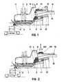
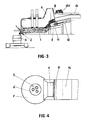
- the electric oven of the invention which is a stationary oven and which comprises a conventional hearth 1 made of refractory material provided with a evacuation of liquid steel to a pocket 3 constituted by a conventional nozzle nozzle 2, has its inner enclosure produced in a very particular way, because defining, beside the floor 1 and with the floor 9, a lateral space 4 of fairly large volume intended for prior storage of cold scrap before their introduction into the melting zone, that is to say on the floor 1, where the electric arcs coming from the electrodes 5 act.
- the lateral space 4 has a large volume, for example of the order of a good third of the entire volume of the interior enclosure of the oven, so that on the one hand can easily introduce large scrap metal and on the other hand we can store a large volume of scrap, this lateral space 4 being connected to the pipe 16 for evacuating smoke from the oven, so as to be crossed by said fumes, which makes it possible to take full advantage of the particular advantage of the invention which consists in recovering the heat of the fumes in order to preheat the scrap before they are introduced into the melting zone.
- the lateral space 4 of the invention has a significant height, of the order of two to three times that of the central part 6 of the roof 7 of the oven by example, which allows, as will be seen below, a particularly advantageous implementation of the invention, on the one hand because it makes it possible to easily supply the space 4 with cold scrap using '' a hatch or door 8 placed at the top of said space, and on the other hand because it makes it possible to take advantage of the optimum preheating of the scrap due to the fumes of the fact that it is possible to feed the sole with the scrap located at the bottom of the pile 10 stored in the lateral space 4, that is to say the hottest because located closest to the active area of the sole, and because having stayed longer in the lateral space 4 than the scrap found at the top of said pile 10.
- the internal enclosure of the oven has, due to the presence of the lateral space 4 of the invention, a tormented shape, which would be very difficult to achieve.
- refractory material apart from sole 1 and zone 6 made of refractory material and apart from most of the floor 9 of the lateral space 4 made in the form of a massive construction and inclined towards the sole as shown in Figure 1, the walls and the top of the oven are metallic and include, in the warmer parts, zones cooled by circulation of water, or other fluid, this technique is now common in the construction of the walls of electric ovens.
- a steel block 11 serving as a pusher and actuated by a jack 12 is placed , in its retracted position as shown in Figure 1, on the part of the inclined floor 9 which is external to the oven enclosure.
- the pusher unit 11a in the retracted position, advantageously its front edge situated at the limit or outside of the lateral space 4, so as not to hinder the formation of the pile 10.
- FIG. 1 shows the phase of introduction, into the lateral space 4 of the invention, of a portion 13 of cold scrap added to the pile 10 of already preheated scrap that said space 4 contains.
- the door 8 was opened, by tilting upwards, and the said portion of the door is then pushed, using a dozer. cold scrap inside the lateral space 4 where it falls on top of the pile 10.
- the pusher 11 is advanced forward, by output from the rod of the jack 12, which has the effect, as can be clearly seen in the drawing, of introducing , in the laboratory delimited by sole 1, only the lower part of the scrap pile 10, which is the warmest part not only because it is located closest to the zone of maximum radiation, but also because it stayed the longest in the lateral space 4, as can be seen on examining FIGS. 1 and 2, and was traversed by the fumes sucked in by the exhaust pipe 16.
Landscapes
- Engineering & Computer Science (AREA)
- Chemical & Material Sciences (AREA)
- Mechanical Engineering (AREA)
- Materials Engineering (AREA)
- Metallurgy (AREA)
- Organic Chemistry (AREA)
- Manufacturing & Machinery (AREA)
- General Engineering & Computer Science (AREA)
- Vertical, Hearth, Or Arc Furnaces (AREA)
- Furnace Details (AREA)
- Manufacture And Refinement Of Metals (AREA)
- Furnace Charging Or Discharging (AREA)
- Processing And Handling Of Plastics And Other Materials For Molding In General (AREA)
- Waste-Gas Treatment And Other Accessory Devices For Furnaces (AREA)
Claims (2)
Priority Applications (1)
| Application Number | Priority Date | Filing Date | Title |
|---|---|---|---|
| AT82400101T ATE20550T1 (de) | 1981-01-20 | 1982-01-20 | Kontinuierlich beschickter elektrolichtbogenofen zum schmelzen von schrott. |
Applications Claiming Priority (2)
| Application Number | Priority Date | Filing Date | Title |
|---|---|---|---|
| FR8100996A FR2498309B1 (fr) | 1981-01-20 | 1981-01-20 | Four electrique destine a la fusion de ferrailles et alimente en continu |
| FR8100996 | 1981-01-20 |
Publications (2)
| Publication Number | Publication Date |
|---|---|
| EP0056773A1 EP0056773A1 (de) | 1982-07-28 |
| EP0056773B1 true EP0056773B1 (de) | 1986-06-25 |
Family
ID=9254332
Family Applications (1)
| Application Number | Title | Priority Date | Filing Date |
|---|---|---|---|
| EP19820400101 Expired EP0056773B1 (de) | 1981-01-20 | 1982-01-20 | Kontinuierlich beschickter Elektrolichtbogenofen zum Schmelzen von Schrott |
Country Status (7)
| Country | Link |
|---|---|
| US (1) | US4423514A (de) |
| EP (1) | EP0056773B1 (de) |
| JP (1) | JPS5925139B2 (de) |
| AT (1) | ATE20550T1 (de) |
| CA (1) | CA1173880A (de) |
| DE (1) | DE3271809D1 (de) |
| FR (1) | FR2498309B1 (de) |
Families Citing this family (25)
| Publication number | Priority date | Publication date | Assignee | Title |
|---|---|---|---|---|
| US4445849A (en) * | 1981-05-25 | 1984-05-01 | Swiss Aluminium Ltd. | Device for thermal treatment of scrap |
| FR2539861B1 (fr) * | 1983-01-20 | 1987-08-07 | Ferco Int Usine Ferrures | Dispositif d'alimentation automatique du creuset d'une machine a couler sous pression en chambre chaude |
| FR2562222B1 (fr) * | 1984-03-28 | 1986-08-01 | Litchinko Catherine | Installation et procede pour charger en continu un reacteur, en matiere solide et rechauffer cette derniere avec les gaz emis par le reacteur |
| DE3421485A1 (de) * | 1984-06-08 | 1985-12-12 | Fuchs Systemtechnik GmbH, 7601 Willstätt | Lichtbogenofen mit einem auf einer seite des ofengefaesses vorgesehenen aufnahmeraum fuer chargiergut |
| EP0291680B2 (de) * | 1984-06-08 | 1995-03-01 | Fuchs Systemtechnik GmbH | Lichtbogenofen mit einem auf einer Seite des Ofengefässes vorgesehenen Aufnahmeraum für Chargiergut |
| US4564388A (en) * | 1984-08-02 | 1986-01-14 | Intersteel Technology, Inc. | Method for continuous steelmaking |
| AU604228B2 (en) * | 1986-02-24 | 1990-12-13 | John Didea | Improved method of disposal and recycling of scrap metal from sea and other vessels |
| DE3906653A1 (de) * | 1989-03-02 | 1990-09-06 | Fuchs Technology Ag | Einschmelzaggregat mit schachtfoermigem chargiergutvorwaermer |
| AT391757B (de) * | 1989-04-13 | 1990-11-26 | Voest Alpine Ind Anlagen | Anlage zur metallurgischen behandlung von metallen, metallverbindungen und/oder metall-legierungen |
| US5071047A (en) * | 1990-06-04 | 1991-12-10 | Claire Cordisco | Baby carrier |
| JPH0754797Y2 (ja) * | 1990-11-07 | 1995-12-18 | 新日本製鐵株式会社 | 連続スクラップ装入式アーク炉の炉体構造 |
| US5634960A (en) * | 1995-02-16 | 1997-06-03 | Elkem A/S | Scrap melting in a submerged arc furnace |
| DE19945489A1 (de) * | 1999-09-22 | 2001-04-05 | Sms Demag Ag | Verfahren und Einrichtung zum Einbringen von Schüttgut in ein metallurgisches Gefäss |
| US6473446B2 (en) * | 2000-12-13 | 2002-10-29 | Sms Demag, Inc. | Electric furnace for steel making |
| US6801563B2 (en) * | 2001-11-07 | 2004-10-05 | Sms Demag, Inc. | Apparatus to manipulate scrap in a scrap charger |
| RU2231725C2 (ru) * | 2002-07-12 | 2004-06-27 | ОАО Верхнесалдинское металлургическое производственное объединение | Холодный под плавильной печи |
| WO2004036131A1 (en) * | 2002-10-15 | 2004-04-29 | Sms Demag Ag | Electric furnace for steel making |
| EP2014742B1 (de) * | 2006-04-28 | 2018-08-08 | JP Steel Plantech Co. | Vorrichtung und verfahren zur zufuhr von glühendem koks |
| US8702367B2 (en) * | 2007-03-21 | 2014-04-22 | Edw. C. Levy Co. | Method, and process for preparing a recyclable material |
| RU2413017C2 (ru) * | 2009-04-06 | 2011-02-27 | Открытое Акционерное Общество "Корпорация Всмпо-Ависма" | Плавильная печь с холодным подом |
| DE102010049238A1 (de) | 2010-10-25 | 2012-04-26 | Intracon Gmbh | Schrott-Schubvorrichtung |
| CN102183150B (zh) * | 2011-04-25 | 2013-07-03 | 中冶赛迪工程技术股份有限公司 | 用于向电炉中加入废钢的快速加料装置及其加料方法 |
| DE102011087065A1 (de) | 2011-11-24 | 2013-05-29 | Sms Siemag Ag | Elektrolichtbogenofen und Verfahren zu seinem Betrieb |
| CN203132356U (zh) * | 2011-12-27 | 2013-08-14 | 钢铁普蓝特克股份有限公司 | 电弧炉 |
| CN108085507A (zh) * | 2016-11-23 | 2018-05-29 | 攀枝花市九鼎智远知识产权运营有限公司 | 一种基于电子束冷床炉的进料系统 |
Family Cites Families (9)
| Publication number | Priority date | Publication date | Assignee | Title |
|---|---|---|---|---|
| DE148129C (de) * | ||||
| US1522665A (en) * | 1922-02-16 | 1925-01-13 | Wright Parvin | Electric furnace and method of operating the same |
| DE1250644B (de) * | 1964-01-14 | 1900-01-01 | ||
| US3441651A (en) * | 1966-02-23 | 1969-04-29 | Canadian Patents Dev | Method and apparatus for heat recovery in electric arc furnaces |
| FR1602675A (de) * | 1968-07-31 | 1971-01-11 | ||
| BE755725A (fr) * | 1969-10-23 | 1971-02-15 | Huettenwerk Oberhausen Ag | Four a arc pourvu d'un dispositif chargeur d'eponge de fer |
| US3896257A (en) * | 1970-09-24 | 1975-07-22 | Sadamu Kinoshita | Electric arc furnace for melting metals and metal melting method using such furnace |
| DE2434747A1 (de) * | 1974-07-19 | 1976-01-29 | Krupp Gmbh | Verfahren zur herstellung von metall, insbesondere stahl, durch reduzieren und erschmelzen aus schrott und feinkoernigen metalloxiden mittels elektrischer energie und anlage zur durchfuehrung des verfahrens |
| US4225745A (en) * | 1978-09-05 | 1980-09-30 | Harwell Earnest W | Method for charging small particles of iron or steel directly into molten metal in an arc furnace |
-
1981
- 1981-01-20 FR FR8100996A patent/FR2498309B1/fr not_active Expired
- 1981-11-30 US US06/325,951 patent/US4423514A/en not_active Expired - Fee Related
-
1982
- 1982-01-13 JP JP57003993A patent/JPS5925139B2/ja not_active Expired
- 1982-01-19 CA CA000394460A patent/CA1173880A/fr not_active Expired
- 1982-01-20 DE DE8282400101T patent/DE3271809D1/de not_active Expired
- 1982-01-20 AT AT82400101T patent/ATE20550T1/de not_active IP Right Cessation
- 1982-01-20 EP EP19820400101 patent/EP0056773B1/de not_active Expired
Non-Patent Citations (1)
| Title |
|---|
| H. Lecompte Cours d'Acierie, Editions de la Revue de Metallurgie, p. 167,171 * |
Also Published As
| Publication number | Publication date |
|---|---|
| DE3271809D1 (en) | 1986-07-31 |
| US4423514A (en) | 1983-12-27 |
| FR2498309A1 (fr) | 1982-07-23 |
| JPS5925139B2 (ja) | 1984-06-14 |
| ATE20550T1 (de) | 1986-07-15 |
| CA1173880A (fr) | 1984-09-04 |
| FR2498309B1 (fr) | 1986-04-11 |
| JPS57142477A (en) | 1982-09-03 |
| EP0056773A1 (de) | 1982-07-28 |
Similar Documents
| Publication | Publication Date | Title |
|---|---|---|
| EP0056773B1 (de) | Kontinuierlich beschickter Elektrolichtbogenofen zum Schmelzen von Schrott | |
| EP0462898B1 (de) | Verfahren und Einrichtung zum Schmelzen einer Ladung im Ofen | |
| CA2017132C (fr) | Creuset froid a vidange par le fond | |
| EP0649477B1 (de) | Elektroofen zum schmelzen von schrott | |
| EP0514526A1 (de) | Vorrichtung zur herstellung von schmelzflüssigem metall im elektroofen. | |
| EP0734458B1 (de) | Vorrichtung zum beschicken eines elektrofens mit flüssigmetall | |
| FR2517422A1 (fr) | Procede et dispositif de recuperation de gaz combustibles dans un four d'electrometallurgie | |
| CA2295393A1 (fr) | Repartiteur de coulee continue des metaux, du type comportant au moins une torche a plasma pour le rechauffage du metal | |
| EP1457575B1 (de) | Vorrichtung zum Beobachten von Chargiergut in einem Elektrostahlofen | |
| EP0666325B1 (de) | Gleichstromofen zum Schmelzen von Metall | |
| EP0468832B1 (de) | Ofen zum Halten der Temperatur und zur metallurgischen Behandlung | |
| EP1784611A1 (de) | Abschlackungstürverschluss für elektrolichtbogenofen | |
| EP0768017B1 (de) | Ofen und herstellungsverfahren für geschmolzene erzeugnisse | |
| FR2931482A1 (fr) | Procede de craquage en continu de dechets de polyolefines | |
| KR101184440B1 (ko) | 알루미늄과 스테인레스강판으로 이루어진 겹구조의 금속스크랩 재활용을 위한 금속스크랩 분리 방법 | |
| BE532283A (de) | ||
| FR2852089A1 (fr) | Bouchon de porte de decrassage de four electrique a arcs | |
| CH239997A (fr) | Procédé d'extraction du magnésium par voie électro-thermique et nouveau four électrique pour la mise en oeuvre de ce procédé. | |
| BE550259A (de) | ||
| BE423557A (de) | ||
| LU88440A1 (fr) | Dispositif de chargement d'un four électrique | |
| FR2811071A1 (fr) | Four a thermoplongeurs electriques pour le chauffage a coeur de metal liquide non ferreux | |
| FR2692971A1 (fr) | Procédé et four pour le maintien à l'état liquide d'une charge métallique. | |
| FR2670504A1 (fr) | Installation de fusion de ferraille pour la production d'acier. | |
| BE491701A (de) |
Legal Events
| Date | Code | Title | Description |
|---|---|---|---|
| PUAI | Public reference made under article 153(3) epc to a published international application that has entered the european phase |
Free format text: ORIGINAL CODE: 0009012 |
|
| AK | Designated contracting states |
Designated state(s): AT BE CH DE FR GB IT LU NL SE |
|
| 17P | Request for examination filed |
Effective date: 19820630 |
|
| RAP1 | Party data changed (applicant data changed or rights of an application transferred) |
Owner name: CLECIM SA |
|
| GRAA | (expected) grant |
Free format text: ORIGINAL CODE: 0009210 |
|
| AK | Designated contracting states |
Kind code of ref document: B1 Designated state(s): AT BE CH DE FR GB IT LI LU NL SE |
|
| REF | Corresponds to: |
Ref document number: 20550 Country of ref document: AT Date of ref document: 19860715 Kind code of ref document: T |
|
| ITF | It: translation for a ep patent filed | ||
| REF | Corresponds to: |
Ref document number: 3271809 Country of ref document: DE Date of ref document: 19860731 |
|
| PLBE | No opposition filed within time limit |
Free format text: ORIGINAL CODE: 0009261 |
|
| STAA | Information on the status of an ep patent application or granted ep patent |
Free format text: STATUS: NO OPPOSITION FILED WITHIN TIME LIMIT |
|
| 26N | No opposition filed | ||
| PGFP | Annual fee paid to national office [announced via postgrant information from national office to epo] |
Ref country code: CH Payment date: 19920127 Year of fee payment: 11 |
|
| ITTA | It: last paid annual fee | ||
| PG25 | Lapsed in a contracting state [announced via postgrant information from national office to epo] |
Ref country code: LI Effective date: 19930131 Ref country code: CH Effective date: 19930131 |
|
| REG | Reference to a national code |
Ref country code: CH Ref legal event code: PL |
|
| PGFP | Annual fee paid to national office [announced via postgrant information from national office to epo] |
Ref country code: FR Payment date: 19931223 Year of fee payment: 13 |
|
| PGFP | Annual fee paid to national office [announced via postgrant information from national office to epo] |
Ref country code: GB Payment date: 19940111 Year of fee payment: 13 |
|
| PGFP | Annual fee paid to national office [announced via postgrant information from national office to epo] |
Ref country code: SE Payment date: 19940118 Year of fee payment: 13 |
|
| PGFP | Annual fee paid to national office [announced via postgrant information from national office to epo] |
Ref country code: AT Payment date: 19940121 Year of fee payment: 13 |
|
| PGFP | Annual fee paid to national office [announced via postgrant information from national office to epo] |
Ref country code: NL Payment date: 19940131 Year of fee payment: 13 Ref country code: LU Payment date: 19940131 Year of fee payment: 13 Ref country code: DE Payment date: 19940131 Year of fee payment: 13 |
|
| PGFP | Annual fee paid to national office [announced via postgrant information from national office to epo] |
Ref country code: BE Payment date: 19940209 Year of fee payment: 13 |
|
| EPTA | Lu: last paid annual fee | ||
| PG25 | Lapsed in a contracting state [announced via postgrant information from national office to epo] |
Ref country code: LU Free format text: LAPSE BECAUSE OF NON-PAYMENT OF DUE FEES Effective date: 19950120 Ref country code: GB Effective date: 19950120 Ref country code: AT Effective date: 19950120 |
|
| PG25 | Lapsed in a contracting state [announced via postgrant information from national office to epo] |
Ref country code: SE Effective date: 19950121 |
|
| EAL | Se: european patent in force in sweden |
Ref document number: 82400101.0 |
|
| PG25 | Lapsed in a contracting state [announced via postgrant information from national office to epo] |
Ref country code: BE Effective date: 19950131 |
|
| BERE | Be: lapsed |
Owner name: CLECIM SA Effective date: 19950131 |
|
| PG25 | Lapsed in a contracting state [announced via postgrant information from national office to epo] |
Ref country code: NL Effective date: 19950801 |
|
| GBPC | Gb: european patent ceased through non-payment of renewal fee |
Effective date: 19950120 |
|
| PG25 | Lapsed in a contracting state [announced via postgrant information from national office to epo] |
Ref country code: FR Effective date: 19950929 |
|
| NLV4 | Nl: lapsed or anulled due to non-payment of the annual fee |
Effective date: 19950801 |
|
| PG25 | Lapsed in a contracting state [announced via postgrant information from national office to epo] |
Ref country code: DE Effective date: 19951003 |
|
| EUG | Se: european patent has lapsed |
Ref document number: 82400101.0 |
|
| REG | Reference to a national code |
Ref country code: FR Ref legal event code: ST |