EP0056778B1 - Vorrichtung zum Verlegen von einem Kabel in einem Graben auf dem Meeresboden - Google Patents
Vorrichtung zum Verlegen von einem Kabel in einem Graben auf dem Meeresboden Download PDFInfo
- Publication number
- EP0056778B1 EP0056778B1 EP19820430001 EP82430001A EP0056778B1 EP 0056778 B1 EP0056778 B1 EP 0056778B1 EP 19820430001 EP19820430001 EP 19820430001 EP 82430001 A EP82430001 A EP 82430001A EP 0056778 B1 EP0056778 B1 EP 0056778B1
- Authority
- EP
- European Patent Office
- Prior art keywords
- cable
- trench
- arm
- sea bed
- pivoting
- Prior art date
- Legal status (The legal status is an assumption and is not a legal conclusion. Google has not performed a legal analysis and makes no representation as to the accuracy of the status listed.)
- Expired
Links
- 238000009933 burial Methods 0.000 claims description 6
- 230000000694 effects Effects 0.000 claims description 6
- 230000009471 action Effects 0.000 claims description 5
- 238000006073 displacement reaction Methods 0.000 claims description 4
- 230000001939 inductive effect Effects 0.000 claims 1
- 238000010586 diagram Methods 0.000 description 12
- 125000006850 spacer group Chemical group 0.000 description 8
- 238000000034 method Methods 0.000 description 4
- 239000012530 fluid Substances 0.000 description 3
- 230000000284 resting effect Effects 0.000 description 3
- 238000003466 welding Methods 0.000 description 3
- 230000008901 benefit Effects 0.000 description 2
- 230000008878 coupling Effects 0.000 description 2
- 238000010168 coupling process Methods 0.000 description 2
- 238000005859 coupling reaction Methods 0.000 description 2
- 230000007423 decrease Effects 0.000 description 2
- 238000005304 joining Methods 0.000 description 2
- 238000012423 maintenance Methods 0.000 description 2
- 230000008439 repair process Effects 0.000 description 2
- 229920003051 synthetic elastomer Polymers 0.000 description 2
- 239000005061 synthetic rubber Substances 0.000 description 2
- 229910000906 Bronze Inorganic materials 0.000 description 1
- XEEYBQQBJWHFJM-UHFFFAOYSA-N Iron Chemical group [Fe] XEEYBQQBJWHFJM-UHFFFAOYSA-N 0.000 description 1
- 230000005540 biological transmission Effects 0.000 description 1
- 239000010974 bronze Substances 0.000 description 1
- 230000015556 catabolic process Effects 0.000 description 1
- 238000004891 communication Methods 0.000 description 1
- 239000004020 conductor Substances 0.000 description 1
- KUNSUQLRTQLHQQ-UHFFFAOYSA-N copper tin Chemical compound [Cu].[Sn] KUNSUQLRTQLHQQ-UHFFFAOYSA-N 0.000 description 1
- 238000006731 degradation reaction Methods 0.000 description 1
- 230000001419 dependent effect Effects 0.000 description 1
- 230000006866 deterioration Effects 0.000 description 1
- 239000000463 material Substances 0.000 description 1
- 239000002184 metal Substances 0.000 description 1
- 229910052751 metal Inorganic materials 0.000 description 1
- 238000005192 partition Methods 0.000 description 1
- 230000035515 penetration Effects 0.000 description 1
- 230000000704 physical effect Effects 0.000 description 1
- 238000003825 pressing Methods 0.000 description 1
- 230000008569 process Effects 0.000 description 1
- 238000007789 sealing Methods 0.000 description 1
- 238000003860 storage Methods 0.000 description 1
Images




Classifications
-
- E—FIXED CONSTRUCTIONS
- E02—HYDRAULIC ENGINEERING; FOUNDATIONS; SOIL SHIFTING
- E02F—DREDGING; SOIL-SHIFTING
- E02F5/00—Dredgers or soil-shifting machines for special purposes
- E02F5/02—Dredgers or soil-shifting machines for special purposes for digging trenches or ditches
- E02F5/10—Dredgers or soil-shifting machines for special purposes for digging trenches or ditches with arrangements for reinforcing trenches or ditches; with arrangements for making or assembling conduits or for laying conduits or cables
- E02F5/104—Dredgers or soil-shifting machines for special purposes for digging trenches or ditches with arrangements for reinforcing trenches or ditches; with arrangements for making or assembling conduits or for laying conduits or cables for burying conduits or cables in trenches under water
- E02F5/106—Dredgers or soil-shifting machines for special purposes for digging trenches or ditches with arrangements for reinforcing trenches or ditches; with arrangements for making or assembling conduits or for laying conduits or cables for burying conduits or cables in trenches under water using ploughs, coulters, rippers
-
- E—FIXED CONSTRUCTIONS
- E02—HYDRAULIC ENGINEERING; FOUNDATIONS; SOIL SHIFTING
- E02F—DREDGING; SOIL-SHIFTING
- E02F5/00—Dredgers or soil-shifting machines for special purposes
- E02F5/02—Dredgers or soil-shifting machines for special purposes for digging trenches or ditches
- E02F5/06—Dredgers or soil-shifting machines for special purposes for digging trenches or ditches with digging elements mounted on an endless chain
-
- E—FIXED CONSTRUCTIONS
- E02—HYDRAULIC ENGINEERING; FOUNDATIONS; SOIL SHIFTING
- E02F—DREDGING; SOIL-SHIFTING
- E02F5/00—Dredgers or soil-shifting machines for special purposes
- E02F5/02—Dredgers or soil-shifting machines for special purposes for digging trenches or ditches
- E02F5/10—Dredgers or soil-shifting machines for special purposes for digging trenches or ditches with arrangements for reinforcing trenches or ditches; with arrangements for making or assembling conduits or for laying conduits or cables
- E02F5/104—Dredgers or soil-shifting machines for special purposes for digging trenches or ditches with arrangements for reinforcing trenches or ditches; with arrangements for making or assembling conduits or for laying conduits or cables for burying conduits or cables in trenches under water
- E02F5/105—Dredgers or soil-shifting machines for special purposes for digging trenches or ditches with arrangements for reinforcing trenches or ditches; with arrangements for making or assembling conduits or for laying conduits or cables for burying conduits or cables in trenches under water self-propulsed units moving on the underwater bottom
-
- E—FIXED CONSTRUCTIONS
- E02—HYDRAULIC ENGINEERING; FOUNDATIONS; SOIL SHIFTING
- E02F—DREDGING; SOIL-SHIFTING
- E02F5/00—Dredgers or soil-shifting machines for special purposes
- E02F5/02—Dredgers or soil-shifting machines for special purposes for digging trenches or ditches
- E02F5/10—Dredgers or soil-shifting machines for special purposes for digging trenches or ditches with arrangements for reinforcing trenches or ditches; with arrangements for making or assembling conduits or for laying conduits or cables
- E02F5/104—Dredgers or soil-shifting machines for special purposes for digging trenches or ditches with arrangements for reinforcing trenches or ditches; with arrangements for making or assembling conduits or for laying conduits or cables for burying conduits or cables in trenches under water
- E02F5/109—Dredgers or soil-shifting machines for special purposes for digging trenches or ditches with arrangements for reinforcing trenches or ditches; with arrangements for making or assembling conduits or for laying conduits or cables for burying conduits or cables in trenches under water using rotating digging elements
-
- F—MECHANICAL ENGINEERING; LIGHTING; HEATING; WEAPONS; BLASTING
- F16—ENGINEERING ELEMENTS AND UNITS; GENERAL MEASURES FOR PRODUCING AND MAINTAINING EFFECTIVE FUNCTIONING OF MACHINES OR INSTALLATIONS; THERMAL INSULATION IN GENERAL
- F16L—PIPES; JOINTS OR FITTINGS FOR PIPES; SUPPORTS FOR PIPES, CABLES OR PROTECTIVE TUBING; MEANS FOR THERMAL INSULATION IN GENERAL
- F16L1/00—Laying or reclaiming pipes; Repairing or joining pipes on or under water
- F16L1/12—Laying or reclaiming pipes on or under water
- F16L1/16—Laying or reclaiming pipes on or under water on the bottom
-
- F—MECHANICAL ENGINEERING; LIGHTING; HEATING; WEAPONS; BLASTING
- F16—ENGINEERING ELEMENTS AND UNITS; GENERAL MEASURES FOR PRODUCING AND MAINTAINING EFFECTIVE FUNCTIONING OF MACHINES OR INSTALLATIONS; THERMAL INSULATION IN GENERAL
- F16L—PIPES; JOINTS OR FITTINGS FOR PIPES; SUPPORTS FOR PIPES, CABLES OR PROTECTIVE TUBING; MEANS FOR THERMAL INSULATION IN GENERAL
- F16L1/00—Laying or reclaiming pipes; Repairing or joining pipes on or under water
- F16L1/26—Repairing or joining pipes on or under water
- F16L1/265—Underwater vehicles moving on the bottom
-
- H—ELECTRICITY
- H02—GENERATION; CONVERSION OR DISTRIBUTION OF ELECTRIC POWER
- H02G—INSTALLATION OF ELECTRIC CABLES OR LINES, OR OF COMBINED OPTICAL AND ELECTRIC CABLES OR LINES
- H02G1/00—Methods or apparatus specially adapted for installing, maintaining, repairing or dismantling electric cables or lines
- H02G1/06—Methods or apparatus specially adapted for installing, maintaining, repairing or dismantling electric cables or lines for laying cables, e.g. laying apparatus on vehicle
- H02G1/10—Methods or apparatus specially adapted for installing, maintaining, repairing or dismantling electric cables or lines for laying cables, e.g. laying apparatus on vehicle in or under water
Definitions
- the present invention relates to a device for setting up a cable in a trench made at the bottom of the sea.
- the technical sector of the invention is that of underwater work and more particularly that of the equipment used in the context of such work.
- Materials are already known for making cables buried in the sea floor. Some of these devices are operated by divers, are adapted to move on the bottom and include a ploughshare which digs a trench in which the cable is buried. Other devices include, instead of a ploughshare, an excavator for digging the trench.
- a tractor mounted on tracks comprising the means of digging the trench, handling cables and.
- a mobile machine coming to adapt to the tractor and from which machine the control commands to the engine, steering, excavator and handling devices carried by the tractor, are transmitted.
- a machine for burying submarine cables corresponding to the preamble of claim 1 (US-A-3 434 297), which consists of two crawler tractors, connected to each other by a joint d 'joint.
- the front tractor comprises at the front an articulated beam for pivoting in the vertical and horizontal direction and adopting, at the end of the races, a position inclined towards the ground and a position substantially parallel thereto.
- the two tractors were lowered to the bottom of the sea at the same time using a cable from a surface support.
- Said beam carried by the front tractor has a jaw to take the cable, raise it until the beam is horizontal and bury it in the trench.
- Said jaw is movable along the beam and has the function of pulling the cable backwards during the advancement of the machine.
- the excavator has nozzles for digging the trench in the seabed.
- Said excavator comprises a slide of a U-shaped cross section, open at its lower part and forming a curved wall on which the cable
- the present invention relates to an apparatus of a new design compared to currently known devices, this apparatus being furthermore suitable for burying cables in particular electric cables under conditions of safety for cables, imposed due to the structure of such cables, which are composed of heterogeneous elements.
- the cables When they are laid at the bottom of the sea, before they are buried in a trench practiced in the sea floor, the cables, coming from a surface support, for example a barge, are, according to a technique, unwound from of the latter to be deposited on the merits. Given their weight and the friction of the cables on the bottom, as they are unwound and therefore the length of cables supported by their own weight on the sea floor, tension is created in the cables. This tension known as “laying tension can reach an excessive value at which it is excluded to practice the burial of the cables in this state, without risks of subsequent degradation due to the permanent fatigue of the cables.
- the objective of the present invention is an apparatus suitable for burying cables, in particular electric cables in the sea floor, and reducing the voltage in said cables to an acceptable value for burying them in this state in the seabed.
- the invention as characterized in claim 1 achieves this objective.
- An advantage of the device according to the invention is at the level of its constitution of the fact that it is composed of two parts, one called “inert", intended to remain at the bottom of the sea for the duration of the works and the other mobile , which can be handled from a surface support, or can also be autonomous, includes all the equipment necessary to carry out the work to be carried out: power plants, drive units and excavator for digging the trench .
- Said mobile machine is supplied with electrical energy by the surface support.
- the mobile machine can couple and disassociate itself from the “inert” assembly resting on the seabed, without the intervention of divers.
- Said device may be reassembled on board the surface vessel for maintenance or repair.
- the inert assembly inside which the cables circulate normally remains at the bottom permanently; however, in the event of an incident, pioneers can clear the cables and all or part of the inert assembly can be reassembled for repair on board the surface support.
- the handling arms are, in one embodiment, two in number respectively on port and starboard at the front of the device.
- the articulation of the part of the inert assembly to the other comprising the cable guides and the trench support, and that of the beam which carries the excavator to the mobile machine allow the device to acknowledge changes in directions while it is operational.
- the cable locking device prevents any harmful tensioning of the part of the cables already buried at the bottom of the sea.
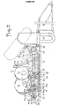
- FIG. 2 of the drawing schematically illustrates a device according to the invention.
- This consists of a mobile device 1 and a so-called “2/3/4 inert” assembly, adapted to be supported by mobile device 1.
- the mobile machine 1 consists of a structure on which are mounted at the bottom of the tracks 1a which span the "inert" assembly.
- This machine 1 comprises, at its upper part, a spherical cabin 1b communicating with an airlock 1c also spherical as well as an excavator 1d.
- the cockpit and its airlock are located at the front of the machine, the excavator is located in the longitudinal axis of the machine, at the rear, so that it can be put in the right working position forward and substantially in the axis of the trench support member 4, as illustrated by the solid line in FIG. 2.
- the various positions that the l 1d excavator This is mounted articulated at the end of a beam 1e around a substantially horizontal axis 1f in order to be able to pivot in a vertical plane.
- the beam 1e which composes the operating member of the excavator to lower it into the digging position of the trench or raise it to put it in the rest and operating position of the mobile machine is articulated around a substantially horizontal axis 1g.
- the beam 1e is articulated at its end opposite to that where the excavator 1d is articulated, around an axis 1 h substantially perpendicular to its longitudinal axis, which axis 1 is located in a vertical plane.
- the beam 1e is thus articulated on the one hand to pivot in the transverse direction around the axis 1h, and on the other hand to pivot in the vertical direction, around the axis 1g, which is engaged in an intermediate piece 1j , called nuts.
- two rods 1 k mounted on the one hand around the axis 1g and around an axis 11, fixed to the structure of the machine, support the beam at the level of the nut 1 j.
- the rods 1 k are located on either side of the nut 1j, which comprises a yoke 1j, in which is mounted around an axis 1J 2 the movable rod of a double-acting cylinder 5, articulated by the free end of its body to the structure of the machine 1 around an axis 5 1 ,
- the raising and lowering of the beam 1e is caused by a double-acting cylinder 6, articulated at the door around a substantially horizontal axis 6 1 and around an axis 6 2 mounted in a yoke fixed to a gantry 1 m arranged transversely to the machine 1 and partly overlapping the airlock 1c.
- the 1m gantry is slightly inclined towards the side of said airlock.
- the pivoting of the 1d excavator around the beam 1e is caused by two double-acting cylinders 7, articulated around an axis 7 1 connected to the beam and parallel to the axis 6 1 , and around another axis 7 2 mounted in a yoke 1 fixed to the structure of the excavator and located above the axis 1f around which it pivots.
- the excavator 1d carried by the beam 1e, can be moved back under the effect of the jack 5, which, pressing on the axis 5 i , causes the pivoting of the rods 1 K under the effect of the deployment of its movable rod and correlatively the movement from front to back of the excavator.
- An intervention on the cylinders 6/7 makes it possible to maintain the excavator in a substantially vertical position and to disengage it during the digging of the trench if for some reason the bucket chain were to become blocked or engorged or in the event of damage.
- the mobile machine 1 comprises all the equipment necessary for the underwater work to be carried out and in particular the power plants and the engine members. It is connected to the surface support by an umbilical (not shown in the drawing), the electrical energy supplied by the carrier ship is in particular conveyed by the umbilical to the mobile machine.
- the mobile machine 1 also comprises part of the means for stress relieving the electric cables, which are arranged at the front of the device, another part of these means being carried by the "inert" assembly 2/3/4. These means, shown in detail in Figure 7, will be described later.
- the inert assembly 2/3/4 consists of a frame 2, connected to an intermediate element 3, comprising cable guides, which is also connected to the trench holding member 4.
- the frame 2 made in mechanical welding is. consists of a very thick sheet 2a, stiffened by sails, comprising two extensions 2b extending in the direction of advancement of the device and located on either side of the frame. Each of these extensions comprises below the sheet 2a and along each of the lateral sides of the frame, a housing 2c intended to receive a horn of a handling member which will be discussed later.
- This housing is of a cross section, preferably square, and can be opened at its lower part. Its internal side wall 2d is folded into 2d 1 to form a flared entry intended to facilitate penetration of the horn into the housing.
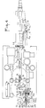
- the frame 2 comprises (fig. 1, 4 and 7) in line with each of the extensions 2b and above the sheet 2a, a handling arm 8, which is articulated on the frame around a horizontal axis 9.
- the arm 8 extends in front of the frame 2 and is of a U-shaped cross section and thus comprises a bottom wall 8a and two side walls 8b.
- the bottom wall 8a is curved and convex and has a profile whose radius is for example 2.50 m for a cable with a diameter included in the following range: 90 to 120 mm.
- the curvature of the wall in the longitudinal direction is established according to the diameter of the cable in order to avoid deterioration of the latter.
- the side walls 8b are parallel over a part of their length 8b i from the point of articulation of the arm and are curved on the side of its free end 8b z , so that they gradually move away from one of the 'other to form a flared entry to facilitate the relative movement of the cable and the machine and also to overcome the misalignment of the cable.
- the walls 8b are connected to the free end of the arm by a tubular spacer 8c.
- Each arm 8 is pivotally mounted in a yoke 2d fixed to the frame 2, at its rear part, and in which the axis 9 is engaged.
- stirrup 8d composed of two lateral flat bars connected at each of their ends by a cylindrical spacer 8d.
- the spacer located at the lower part, is in contact with the lower part of the curved wall 8a of the arm, whatever the angular position of the arm.
- the arm At rest the arm is supported on the spacer 8d, which is supported by the frame 2.
- the upper part 8d 2 of the spacer extends above the arm to allow the introduction of a lifting member which it will question further.
- the spacers are held captive but free to move on the arm by means of four guide bosses 8e fixed to the outer face of each side wall 8b.
- the arms 8 are guided laterally by uprights 2f perpendicular to the sheet 2a and parallel to each other at the rate of two uprights per arm, which uprights have the function of relieving the articulations of the arms when handling the cables.
- the uprights are arranged in front of the stirrups 8d.
- the frame 2 comprises a yoke 2g in which a connecting piece 10 is articulated, which comprises two axes perpendicular to each other and offset from one another: an axis 10a horizontal and engaged in the yoke 2g of the frame 2 and an axis 10b perpendicular to the axis 10a.
- the piece 10 forms a yoke 10c in which the axis 10b has passed to carry out the coupling of the intermediate element 3.
- This essentially consists of a structure comprising cable guides 3a extending along the edges side of the element 3.
- the cable guides 3a are rectilinear tubular elements of a rectangular cross section and their ends 3a 1 / 3a 2 are flared to facilitate the circulation of the cables. They are interconnected at their front part on the side of the frame 2 by means of a spreader 3b in the form of a symmetrical fin, which is articulated at 3b, to said cable guides 3a.
- the elements 3a are an extension of the handling arms 8 and have the function of guiding and protecting the cables: from the frame 2 to the “trench holding 4” member.
- the coupling of the middle assembly 3 to the frame 2 is carried out by means of the part 10 in which the lifter 3b is partially engaged.
- This comprises a sleeve 3b 2 welded at the front and in the middle of the fin.
- the sleeve 3b 2 passed through the yoke 10c of the part 10 receives the axis 10b, which ensures the connection of the frame 2 and the assembly 3, as well as the articulation of one and the other.
- connection of the middle assembly 3 and of the trench holding member 4 is carried out in an articulated manner around two horizontal axes 11.
- Each tubular element 3a has at its rear end a stud 3c pierced transversely.
- This post is engaged in a yoke 4a, fixed to said trench holding member 4.
- the axis 11 is passed through the yoke 4a and into the post 3c and is held in the transverse direction by any known means, for example by means of clips .
- the trench holding member 4 (fig. 5 and 6) is made of very thick mechanically welded sheet metal and is approximately half of its length and on the side of the middle element 3 of a straight section in the form of T.
- Its function is to ensure the continuity of the cables from the rear end of the middle element 3 to the bottom of the trench. It thus has two side walls parallel to each other and spaced from each other by a value corresponding to the width of the trench obtained by means of the excavator 1d. These walls are of a height substantially equal to that of the trench and are located at the front part of the member 4.
- This comprises two conduits 4c originating in the extension and at the level of the cable guides 3a of the middle element 3 and which bend the cables downwards to bring them back on either side of the longitudinal axis of the device and side by side at the bottom of the trench.
- These conduits 4c are composed by walls forming bearing and support surfaces intended to conduct the cables.
- the conduits 4c are of a curved section in their part located on the side of the middle element 3. They each consist of a side wall 4 C1 and a bottom wall 4 Cz . which is curved and convex and extends from the level of the bottom wall of the cable guides 3a to the lower end of the member 4.
- the curvature of the walls 4 C2 depends on the physical characteristics of the cables: their section, stiffness, weight and resistance in particular.
- the conduits 4c converge from front to rear of the member 4 towards the bottom and the longitudinal axis of the trench. At the place 4c 4 where they meet, they have a common partition 4c 4 located in the plane of symmetry of the member 4.
- An inclined plane 4c s extends the walls 4 C2 to the lower end of the maintenance of trench.
- This inclined plane 4c 5 originates substantially at mid-height of the member 4 and extends to said lower part at an angle of the order of 30 ° with the horizontal.
- Said conduits also include an upper wall 4c 6 which constitutes said bearing surface which forces the cables to land on the bottom of the trench.
- This wall 4c 6 is curved at its rear end 407 . which is situated at a height h with respect to the lower structure of the member 4. Its profile is rectilinear at its front part and extends over this part parallel to the inclined plane 4c 5 .
- the cable 12, drawn in dashed lines in FIGS. 2 and 5 and coming from the cable guides 3a of the middle assembly 3 is on the one hand supported by the wall 4c 2 and on the other hand bearing on the curved part 4c 7 of the wall 4ce.
- the trench holding member 4 comprises on the side of the middle assembly 3 a device 4d for leveling the bottom of the trench, which comprises at its lower part, an inclined blade 4d.
- the device 4d is carried by a structure with longitudinal displacement to enable it to perform its function.
- the mobile machine 1 comprises at the front the means for taking over and causing the displacement of the inert assembly 2/3/4 and also for actuating the handling arms 8.
- the mobile machine thus comprises a mechanical structure welded comprising on both sides of the driving position 1b, a very thick veil 13 extending in a plane perpendicular and transverse to the machine 1 and boxes 13a stiffened by veils 13b delimiting the lateral edges of said structure .
- Said boxes 13a are of a rectangular cross section and are in a vertical position. They have inside two bronze slides 13c parallel to each other and between which is disposed a slide of a cross section in H 13d.
- Each slide 13d has, at its lower part, a horn 13e fixed by welding, which extends in a horizontal position on the side of the frame 2 and is intended to be engaged in the housings 2c thereof.
- each slide / slide assembly: 13c / 13d is fixed to the mobile machine 1 to come in the extension of said housings.
- the spacing of the horns 13e is substantially equal to that of the housings 2c of the frame 2.
- Each horn 13e has an extension 13e, at its rear part to which the movable rod of a double-acting cylinder 14 is articulated at 13f, articulated by its other end at 14a, at the upper part of the box 13a.
- These jacks 14 actuate the horns and cause them to move in the vertical direction.
- the mobile machine 1 comprises a single horn 13e, extending in the axis of the machine, which cooperates when taking care of the inert machine 2 with a housing 2c, located in the axis of said machine 2.
- Each veil 13 has, on its face located towards the rear of the device, a very thick gusset 13g extending in a plane perpendicular to the veil 13.
- This gusset has a cantilevered axis 15, offset on the rear of the web 13 and located on the side of the lower part thereof and around which axis 15 is pivotally mounted a lever 16 extending towards the front of the machine and beyond the web 13.
- the pivoting of the levers 16 is caused by double-acting cylinders 17, articulated on the one hand on the lever at 17a and on the other hand on the structure 13 at 17b, around an axis passed through a yoke 13h fixed to the web 13.
- Each lever 16 is made of mechanical welding and comprises at its free end 16a, a notch in the form of a hook, to cooperate with the spacer ad 1 of the stirrup 8d.
- the device comprises braking means controlled from the manned cockpit 1 b of the machine mobile 1.
- These means consist of brake pads 24, carried by the arms 8 of the inert machine 2 and represented by a hatched outline in Figures 2 and 4 of the drawing.
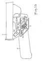
- FIGS. 8 to 11 of the drawing represents an arm 8 in an alternative embodiment with respect to that described with reference to FIG. 7.
- the arm 8 has a bottom wall 8a which is of a curved and convex profile and whose radius is, for example, 2,650 m, for a cable with an outside diameter of 105 mm.
- the side walls 8b are parallel to each other over the almost length of the arm and progressively move apart at its free end 8b 2 to form a flared entry in order to facilitate the movement of the cable in the corridor formed by the walls 8a / 8b.
- the side walls 8b extend to the lower part of the arm 8 and below the bottom wall 8a, so that the arm is of an H-shaped cross section (fig. 9).
- the shoe 24 is in one embodiment, articulated by one of its ends, to the arm 8 around an axis 25 joining the upper side walls 8b and on the side of the front part of the 'arm 8.
- the part 24a coming into contact with the cable is produced from a portion of the split cylindrical tube, of a curved profile and extends parallel to the bottom wall 8a of the arm. Said portion of tube is extended on the side of the joint 25 and is curved at 24a, to form with said bottom wall 8a, a flared inlet located on the side of the front end of the arm.
- the jaw 24 has a central core 24b as well as webs 24c extending transversely to the core 24b and welded to the latter and to the tubular portion 24a.
- the jaw further comprises a parallelepipedal part 24d, extending transversely to the core 24b and parallel to the webs 24c, which part is located approximately two thirds of the length of the jaw counted from the joint 25.
- the part 24d is crossed by an axis 26, immobilized for example by means of a pin 27 engaged in a groove 26a, reserved for the periphery of the axis 26.
- Said axis 26 is extended on either side of the jaw 24 and as illustrated in FIG. 9, moves during the operation of the brake, in notches 8b 3 formed in the side walls 8b of the arm 8.
- the pivoting of the jaw 24 is obtained by means of a single-acting hydraulic cylinder 27 acting on a stirrup 28 articulated to the jaw 24 and around the axis 26.
- the jack 27 is arranged in line with the axis 26 and between the lower side walls 8b of the arm 8 and extends in a direction substantially orthogonal to the bottom wall 8a of the arm.
- the cylinder body has at one end a convex bearing surface 27a, forming a prominence and coming, when the jaw 24 is tightened, to bear on the bottom wall 8a of the arm 8, by means of a counter plate 29 .
- the jack 27 is mounted “free on the arm 8, and is held in position by stud screws 30 screwed into walls 31, located on either side of the jack and welded to the counter plate 29 and to the walls 8b of the arm.
- the piston 27b of the jack extends outside of the body thereof by a rod 27c, the end 27c , which is curved, is in contact with the bottom cross member 28a joining the two side plates 28b of the stirrup 28.
- the lateral plates 28b pass through the bottom wall 8a of the arm passing through openings with a rectangular outline 8a, (fig. 10).
- the stirrup 28 is guided, at its lower part, by iron parts of a square cross section 32, parallel to each other and substantially to the axis XX1 of the jack 27, and welded to the lower walls 8b of the arm.
- the stirrup 28 comprises, at the crosspiece 28a and on either side, attachment points 28c of a U-shaped outline and to which elastic synthetic rubber cables 33 have passed which surround other points d 'fastener 33a, fixed to the arm 8 and below the bottom wall 8a.
- One of the walls 31 has a circular opening in its part.
- median 31a through which the supply duct 27e of the jack has passed, the pressurized fluid of which is supplied by a hose 34, connected to said duct 27e.
- the corridor located above the bottom wall 8a comprises, on either side of the side plates 28b of the stirrups 28, deflectors 35 fixed to the walls 8b of the arm.
- deflectors 35 are portions of split tube of a height greater than the radius of the cable 1. These deflectors are mutually parallel and substantially at the axis of the stirrup XX1.
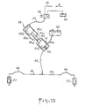
- FIGS. 12 and 13 of the drawing illustrate the hydraulic means which make it possible to actuate the jaw of each of the arms 8.
- FIG. 12 schematically represents the essential members which make up said hydraulic means which equip a machine comprising two handling arms 8.
- the oil pressurized by a hydraulic group, not shown, carried by the mobile machine 1 is sent by a rigid conduit 36 and a hose 37 in a motor cylinder 38 through an electrically controlled fluid distributor 39, connected to an oil box 40 and controlled from the cockpit ib.
- the motor cylinder 38 is a single-acting cylinder and is mounted on the mobile machine. It consists of a body 38a, forming a chamber in which a piston 38b moves, extended by a movable rod 38c which extends outside the body 38a.
- the drive cylinder 38 is located in the extension of a transmitter cylinder 41 carried by the inert machine 2.
- the jack 41 consists of a body 41 a forming a chamber in which a piston 41 b moves. Said piston has an extension 41c forming a cavity 41c1 at its free end.
- the end 38Ci of the rod 38c of the drive cylinder 38 is generally spherical and bears in the cavity 41cl, when the jack 38 is under pressure.
- An opposing spring 42 bearing on the bottom of the chamber 41a and on the piston 41b, tends to push the extension 41c on the side of the drive cylinder 38.
- the chamber 41a is filled with oil and is on the one hand in communication with a tank 43 containing a reserve of compensating oil and on the other hand, connected to said receiving cylinders 27, which actuate the jaws 24 by means of a hose 44 of a rigid pipe 45 and hoses 46.
- FIG. 13 which is a partial view of the mobile 1 and inert 2 machines, shown assembled together, illustrates the situation of the engine jacks 38 and transmitter 41 with respect to the handling arms 8.
- the drive cylinder 38 is arranged at the front and below the part of the chassis of the mobile machine, which covers the inert machine 2.
- the transmitting cylinder 41 is arranged at the upper part of the inert machine 2.
- the two cylinders are in the extension of one another as illustrated in the drawing, so that the motor cylinder 38 is in position to activate the transmitter cylinder 41.
- the inert assembly having been lowered to the bottom of the sea, is waiting on the sea floor, the frame 2 resting on the bottom.
- the handling arms resting on the frame 2 have their stirrups in the vertical standby position.
- the mobile machine for example handled from a surface support, is placed so as to overlap the inert assembly while being behind the frame 2.
- the levers 16 are inclined downward in position A, illustrated in FIG. 7, the horns 13e are lowered and are placed in front of and in the extension of the housings 2c of the frame 2.
- the machine 1 moving on the sea floor, is advanced on the side of the frame 2 and the operator maneuvers it to fully engage the horns 13e in the housings 2c and correspondingly the end of the levers 16 in the stirrups 8d until the spacers Sd 1 come into abutment on the notch forming the hook 16a.
- the frame 2 under the effect of the jacks 14, is raised until its lower end portion is located approximately at a distance d from the ground, of the order of four hundred millimeters.
- the elevation of the frame 2 causes the elevation of the middle assembly 3.
- the machine is then in its operational position.
- the cables 12 are at this time subjected to a tension T2 called the laying tension following their unwinding from the surface support for their deposit on the seabed, this tension being considered to be uniform over the length of the cable such that illustrates the diagram of FIG. 1a, on which the voltage of value T2, plotted on the ordinate of the diagram, is materialized by line 18.
- the length of the cable Dx has been plotted on the abscissa.
- the locking jaws 24 are actuated to immobilize the cable part 12 already buried, so as not to create undesirable tension in this part.
- the ceiling voltage T3 plotted on the ordinate is materialized by the continuous line 19.
- the cables 12 supported by the arms 8 are raised at the point 12a on the diagram, of a height resulting from the cost force F applied to the cable and physical properties, of it.
- the cable 12 subjected to the laying tension T2 is supported on the ground over the distance d 1 . Given the weight of the cable and the friction on the ground, the cable 12 is considered to be “embedded” in point 12b.
- the operator maneuvers the jacks 17 to reduce the hydraulic pressure, which has the effect of pivoting the arms 8 downwards according to a certain angle without putting them in their extreme low position.
- the cables 12 which were subjected to the tension T4 and correspondingly had undergone a maximum admissible elongation A1 are reduced to a tension T5 intermediate between the tensions T2 and T4, with a residual elongation A2, following the relaxation of the traction exerted on the cables.
- the voltage T5 is materialized by the point 20a located on the line 20 below the position of the line 21 materializing the voltage T4.
- This voltage T5 being the voltage in the cable 12 at point 12d distant from point 12b by the value d4.
- the voltage T1 is materialized by the line 23, which voltage is that of the "relaxed" cables.
- the line 23 which voltage is that of the "relaxed" cables.
Landscapes
- Engineering & Computer Science (AREA)
- General Engineering & Computer Science (AREA)
- Mechanical Engineering (AREA)
- Mining & Mineral Resources (AREA)
- Civil Engineering (AREA)
- Structural Engineering (AREA)
- Laying Of Electric Cables Or Lines Outside (AREA)
- Jib Cranes (AREA)
Claims (19)
Applications Claiming Priority (2)
| Application Number | Priority Date | Filing Date | Title |
|---|---|---|---|
| FR8100699A FR2497915B1 (fr) | 1981-01-14 | 1981-01-14 | Dispositif pour mettre en place un cable dans une tranchee pratiquee au fond de la mer |
| FR8100699 | 1981-01-14 |
Publications (2)
| Publication Number | Publication Date |
|---|---|
| EP0056778A1 EP0056778A1 (de) | 1982-07-28 |
| EP0056778B1 true EP0056778B1 (de) | 1985-09-18 |
Family
ID=9254188
Family Applications (1)
| Application Number | Title | Priority Date | Filing Date |
|---|---|---|---|
| EP19820430001 Expired EP0056778B1 (de) | 1981-01-14 | 1982-01-12 | Vorrichtung zum Verlegen von einem Kabel in einem Graben auf dem Meeresboden |
Country Status (3)
| Country | Link |
|---|---|
| EP (1) | EP0056778B1 (de) |
| DE (1) | DE3266258D1 (de) |
| FR (1) | FR2497915B1 (de) |
Families Citing this family (5)
| Publication number | Priority date | Publication date | Assignee | Title |
|---|---|---|---|---|
| GB8301514D0 (en) * | 1983-01-20 | 1983-02-23 | British Petroleum Co Plc | Plough assembly |
| FR2660494B1 (fr) * | 1990-03-29 | 1992-10-16 | Eca | Systeme pour la pose sur un fond sous-marin d'un cable au moyen d'un navire cablier. |
| CN106505503A (zh) * | 2016-12-12 | 2017-03-15 | 乐山福瑞德机电有限责任公司 | 高铁电力电缆槽组合式支架 |
| NL2024240B1 (en) * | 2019-11-14 | 2021-07-29 | Royal Ihc Ltd | Device, method and assembly for providing an elongate element in a seabed |
| IT202100019700A1 (it) | 2021-07-23 | 2023-01-23 | Saipem Spa | Assieme e metodo per l’interro di cavi subacquei |
Family Cites Families (8)
| Publication number | Priority date | Publication date | Assignee | Title |
|---|---|---|---|---|
| GB452141A (en) * | 1934-11-16 | 1936-08-17 | Western Union Telegraph Co | Improvements in or relating to the laying of submarine electric cables |
| USRE20665E (en) * | 1937-02-20 | 1938-03-01 | Method of and apparatus for laying | |
| US2202156A (en) * | 1938-02-23 | 1940-05-28 | Western Union Telegraph Co | Apparatus for laying submarine cables |
| US3434297A (en) * | 1967-01-25 | 1969-03-25 | Bell Telephone Labor Inc | Submarine cable burying machine |
| FR2278854A1 (fr) * | 1974-07-19 | 1976-02-13 | Comex | Engin automoteur pour travailler au fond de l'eau |
| SE401141B (sv) * | 1976-05-03 | 1978-04-24 | Ericsson Telefon Ab L M | Forleggningsverktyg for forleggning av sjokabel i sjobotten |
| FR2388094A1 (fr) * | 1977-04-19 | 1978-11-17 | Blanc Pierre | Machines d'ensouillage et desensouillage de tuyauteries flexibles et de cables sous-marins |
| US4214387A (en) * | 1978-06-01 | 1980-07-29 | Brown & Root, Inc. | Trenching apparatus and method |
-
1981
- 1981-01-14 FR FR8100699A patent/FR2497915B1/fr not_active Expired
-
1982
- 1982-01-12 EP EP19820430001 patent/EP0056778B1/de not_active Expired
- 1982-01-12 DE DE8282430001T patent/DE3266258D1/de not_active Expired
Also Published As
| Publication number | Publication date |
|---|---|
| FR2497915B1 (fr) | 1985-11-22 |
| DE3266258D1 (en) | 1985-10-24 |
| FR2497915A1 (fr) | 1982-07-16 |
| EP0056778A1 (de) | 1982-07-28 |
Similar Documents
| Publication | Publication Date | Title |
|---|---|---|
| EP0099819B1 (de) | Selbstbetriebenes Fahrzeug mit artikulierbarem Arm, einem Behälter und einer anschaltbaren Betriebsanordnung die durch das Fahrzeug getragen wird | |
| CA1136917A (fr) | Attelage "trois points" utilisable aussi bien a l'avant qu'a l'arriere d'un vehicule industriel, agricole, pour travaux publics, ou forestier, par exemple un tracteur | |
| EP0006076B1 (de) | Hebegerät mit freibeweglichem Korb zum Erklettern eines Mastes | |
| EP0149370A2 (de) | Selbstbewegende Vorrichtung im Inneren einer Kanalisation, insbesondere zum Explorieren oder Arbeiten in einiger Entfernung | |
| EP0997062B1 (de) | Landmaschine | |
| CA1054808A (fr) | Dispositif pour enterrer des elements flexibles de grande longueur | |
| EP2940359B1 (de) | Vorrichtung vom typ spannvorrichtung zum kontrollierten einspannen und vorschieben eines länglichen organs | |
| FR2668879A1 (fr) | Systeme d'attelage entre un tracteur et une remorque dy type semi-portee. | |
| CA2234288A1 (fr) | Dispositif de tirage d'un cable de traction dans une canalisation souterraine | |
| EP0056778A1 (de) | Vorrichtung zum Verlegen von einem Kabel in einem Graben auf dem Meeresboden | |
| FR2722458A1 (fr) | Engin motorise de depannage, en particulier de char | |
| FR2470699A1 (fr) | Dispositif commandable a distance d'intervention sur des structures immergees, notamment de raccordement de canalisations sous-marines | |
| FR2493818A1 (fr) | Grue autotractee equipee de supports deployables de stabilisation et de jambes de force mobiles verticalement associees a ces derniers, et support deployable ainsi realise | |
| EP0114146B1 (de) | Universalbohrgerät versehen mit Mitteln zum schnellen Ziehen des Bohrstranges | |
| CA1092551A (fr) | Systeme d'excavation en mer a guidage horizontal de la benne preneuse au moyen de cables | |
| FR2701278A1 (fr) | Procédé de curage et dispositif de curage et d'inspection de collecteurs d'égouts. | |
| FR3121691A1 (fr) | Trancheuse pourvue d’un dispositif de creusage et d’un tapis transversal ajustable. | |
| FR2607531A1 (fr) | Dispositif de forage de sol agissant selon un axe sensiblement horizontal | |
| FR2488636A1 (fr) | Dispositif de deplacement lateral pour charrue | |
| FR2569216A1 (fr) | Dispositif pour le curage, en particulier de saignees perpendiculaires a une voie routiere | |
| FR2730750A1 (fr) | Drague a benne preneuse suspendue | |
| CN113178819B (zh) | 一种可切换套设保护管的海底光纤埋设装置 | |
| EP0823370B1 (de) | Antriebsvorrichtung für einen Verriegelungszylinder eines Fahrwerkslenkers eines Fahrzeuges | |
| FR2608186A1 (fr) | Dispositif de pose et de reprise sur le sol d'une travure de pont mobile | |
| FR2698626A1 (fr) | Dispositif de pompage de fluide et colonne d'alimentation adaptée pour une communication automatique du fluide. |
Legal Events
| Date | Code | Title | Description |
|---|---|---|---|
| PUAI | Public reference made under article 153(3) epc to a published international application that has entered the european phase |
Free format text: ORIGINAL CODE: 0009012 |
|
| AK | Designated contracting states |
Designated state(s): BE DE FR GB IT NL SE |
|
| 17P | Request for examination filed |
Effective date: 19820618 |
|
| ITF | It: translation for a ep patent filed | ||
| GRAA | (expected) grant |
Free format text: ORIGINAL CODE: 0009210 |
|
| AK | Designated contracting states |
Designated state(s): BE DE FR GB IT NL SE |
|
| REF | Corresponds to: |
Ref document number: 3266258 Country of ref document: DE Date of ref document: 19851024 |
|
| PLBE | No opposition filed within time limit |
Free format text: ORIGINAL CODE: 0009261 |
|
| STAA | Information on the status of an ep patent application or granted ep patent |
Free format text: STATUS: NO OPPOSITION FILED WITHIN TIME LIMIT |
|
| 26N | No opposition filed | ||
| PGFP | Annual fee paid to national office [announced via postgrant information from national office to epo] |
Ref country code: DE Payment date: 19890118 Year of fee payment: 8 |
|
| PGFP | Annual fee paid to national office [announced via postgrant information from national office to epo] |
Ref country code: SE Payment date: 19890119 Year of fee payment: 8 |
|
| ITTA | It: last paid annual fee | ||
| PGFP | Annual fee paid to national office [announced via postgrant information from national office to epo] |
Ref country code: GB Payment date: 19890131 Year of fee payment: 8 Ref country code: NL Payment date: 19890131 Year of fee payment: 10 |
|
| PGFP | Annual fee paid to national office [announced via postgrant information from national office to epo] |
Ref country code: BE Payment date: 19890213 Year of fee payment: 8 |
|
| PG25 | Lapsed in a contracting state [announced via postgrant information from national office to epo] |
Ref country code: GB Effective date: 19900112 |
|
| PG25 | Lapsed in a contracting state [announced via postgrant information from national office to epo] |
Ref country code: SE Effective date: 19900113 |
|
| PG25 | Lapsed in a contracting state [announced via postgrant information from national office to epo] |
Ref country code: BE Effective date: 19900131 |
|
| BERE | Be: lapsed |
Owner name: TRAVOCEAN Effective date: 19900131 |
|
| PG25 | Lapsed in a contracting state [announced via postgrant information from national office to epo] |
Ref country code: NL Effective date: 19900801 |
|
| GBPC | Gb: european patent ceased through non-payment of renewal fee | ||
| NLV4 | Nl: lapsed or anulled due to non-payment of the annual fee | ||
| PG25 | Lapsed in a contracting state [announced via postgrant information from national office to epo] |
Ref country code: DE Effective date: 19901002 |
|
| PGFP | Annual fee paid to national office [announced via postgrant information from national office to epo] |
Ref country code: FR Payment date: 19911227 Year of fee payment: 11 |
|
| PG25 | Lapsed in a contracting state [announced via postgrant information from national office to epo] |
Ref country code: FR Effective date: 19920930 |
|
| REG | Reference to a national code |
Ref country code: FR Ref legal event code: ST |
|
| EUG | Se: european patent has lapsed |
Ref document number: 82430001.6 Effective date: 19901106 |