EP0056789A2 - Dispositif de missile sans recul - Google Patents
Dispositif de missile sans recul Download PDFInfo
- Publication number
- EP0056789A2 EP0056789A2 EP82810021A EP82810021A EP0056789A2 EP 0056789 A2 EP0056789 A2 EP 0056789A2 EP 82810021 A EP82810021 A EP 82810021A EP 82810021 A EP82810021 A EP 82810021A EP 0056789 A2 EP0056789 A2 EP 0056789A2
- Authority
- EP
- European Patent Office
- Prior art keywords
- tube
- projectile
- plant according
- missile
- propellant charge
- Prior art date
- Legal status (The legal status is an assumption and is not a legal conclusion. Google has not performed a legal analysis and makes no representation as to the accuracy of the status listed.)
- Granted
Links
Images



Classifications
-
- F—MECHANICAL ENGINEERING; LIGHTING; HEATING; WEAPONS; BLASTING
- F41—WEAPONS
- F41A—FUNCTIONAL FEATURES OR DETAILS COMMON TO BOTH SMALLARMS AND ORDNANCE, e.g. CANNONS; MOUNTINGS FOR SMALLARMS OR ORDNANCE
- F41A1/00—Missile propulsion characterised by the use of explosive or combustible propellant charges
- F41A1/08—Recoilless guns, i.e. guns having propulsion means producing no recoil
Definitions
- the present invention relates to a recoil-free missile system with at least one tube and at least one missile projectile for each tube, this system being intended in particular for anti-tank and anti-aircraft defense, ie moving point targets. Other applications are included.
- missile projectiles There are a variety of weapon systems for fighting tanks and aircraft that use missile projectiles, and recoil-free tubes can be used.
- a very high initial speed is desirable for all missile projectiles, especially those that are not readjusted; if the propellant charge also has to be accelerated, the total weight of the projectile increases and a limit will soon be set for it, especially when such weapon systems are used on the move.
- the rocket tube 1 shows the rocket tube 1 with two rotating rings 2 and 3, in which propellant charges 4 and 5 are located. At the points where the rings 2 and 3 are, gas passage openings 2a and 3a are arranged in the tube. At the rear end of the tube, the outlet nozzle is 6.
- the rocket projectile 7 In the missile tube 1 is the rocket projectile 7, wherein g is a multi-stage rocket is here eunter.
- the first stage 8 At the rear, on the left in FIG. 1, is the first stage 8, which preferably consists of thin, circular films made of nitroglycerin-nitrocellulose.
- the propellant charge of the first stage is arranged around the extension of the nozzle 9 of the second stage 10, which is shown in section in FIG. 2 and will be explained there. This extension has holes 11 through which the gases of the first stage pass for the purpose of pressure relief.
- tail end of the missile g eunteres the tail 12, which consists of three or more wings 13.
- the gases initially pass through the tail unit and give the projectile a rotation corresponding to the position of the wings, for example five revolutions per second, in order to compensate for the unbalance caused by the building and burning of the propellant charges.
- a rotation corresponding to the position of the wings for example five revolutions per second, in order to compensate for the unbalance caused by the building and burning of the propellant charges.
- such an inaccuracy can cause a lateral force due to a shift in the center of gravity, which would result in a drift of 100 m at a distance of 1000 m; This drift can be reduced to a few decimeters by rotating the projectile.
- a swirl stabilization of the projectile is not possible due to the impairment of the shaped charge effect.
- the projectile should be set in rotation immediately at the start, if possible without trains in the tube, ie when using a smooth tube.
- a sealing, multi-part sabot 57 which serves as a guide in the tube, is attached to the missile projectile and releases after the missile has left the tube.
- the head of the projectile which is known per se and is not explained in more detail here, contains the projectile tip 14 and a hollow charge 15, and for example an impact detonator (not shown).
- an impact detonator not shown
- the sequence of a shot is as follows: First, the igniter 45 ignites the black powder charge, which ignites the propellant charge of the first stage 8, which gives the projectile an initial acceleration, the tube also serving as a combustion chamber. The black powder charge simultaneously ignites the propellant charge of the second stage 10, which consists of considerably thick-walled powder rods. Did the floor in the Rohr et wa moved by a caliber length, the first propellant charge 4 of the tube is ignited, whereby the pressure in the tube is kept at a high level. These gases also initially pass through the tail unit 12 to the end nozzle 6. After the projectile has progressed further in the tube, the second propellant charge 5 is ignited, and further propellant charges can follow.
- the propellant charges 4 and 5 and possibly others need not be accelerated. Inside the tube, an internal pressure of the order of 1000 bar builds up, whereby no recoil forces act on the tube and this therefore remains at rest when fired.
- the tube including the bullet can only be used once and for a next shot the entire tube with the bullet must be replaced.
- the tube can be reloaded in a suitable facility, the fastenings 16 and 17 of the rings 2, 3 being removed and the rings being exposed.
- the powder rods of the second stage are introduced through the nozzle 9 into the combustion chamber. After the last powder rod has been introduced, the opening in the sieve grate 18 which closes the second stage 10 is closed by a sieve grate ver closing 19 closed like a bayonet.
- An exemplary embodiment as an anti-tank projectile is given below.
- the tube see FIG. 5, is placed on a tripod-shaped directional mount 20, the upper part 21 of which is designed to enable the tubes to be replaced quickly.
- an electrical or hydraulic straightening aid 22 which can be operated with the hands or feet around the upper part, which also has a telescopic sight 23 and a range finder, relative to the tripod as a function of the distance, the elevation angle and adjust the two straightening angle speeds.
- an adjustment device that allows the riflescope to be adjusted electrically or hydraulically relative to the tube depending on the target distance, the elevation angle and the two target angle speeds so that the correct lead angle of the Tube remains set to the target if the riflescope is constantly adjusted to the target.
- the total weight of the guide carriage, including the hydraulics and the operating aids, is approximately 100 kg.
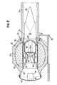
- FIG. 2 is a 200 millimeter caliber.
- the tube 24 which rests on an upper part (not shown) of the directional mount 20 and to which a spherical combustion chamber 27 is fastened by means of a bayonet lock 26, in which the single-stage missile projectile 28 is located.
- the propellant charge 29 contained in the combustion chamber 27 and arranged in a ring around the end of the missile projectile consists of small powder rods with a suitable cross section.
- the missile projectile 28 can have a missile head similar to that in the previous example, with a tip 30 and a shaped charge 31 of 160 mm in diameter.
- the missile projectile can have the same empennage 32 with wings 33, whereby depending on the position of the wings the projectile is given a greater or lesser rotation and the empennage serves to guide the missile in the tube.
- Connected to the tail unit is the combustion chamber 34 of the rocket, which is closed in front of its nozzle 35 by a grating 36 with an opening 36a.
- This combustion chamber 34 like the combustion chamber 10 in the previous example, contains a base 37 which serves as a sabot and which measures the total internal pressure of the tube has to take up about 1000 bar and must therefore have a suitable strength, while in this arrangement the remaining part of this rocket stage is relieved of the internal pipe pressure and only has to be dimensioned for the approximately 10 times smaller combustion chamber pressure of this stage.
- the combustion chamber 34 is loaded with relatively thick powder bars, as in the previous example, the total thrust of which is dimensioned such that it corresponds to the air resistance of the projectile, in order to prevent the drift by the side wind, as described above.
- the missile projectile has a three-part sabot ring 38, which separates from the projectile after leaving the tube.
- the missile projectile is sealed off from the stationary combustion chamber 27 by means of a seal 39.
- the inner wall 40 of the stationary combustion chamber 27 has holes 41 in order to allow the fuel gas to pass through to the missile projectile.
- the stationary combustion chamber 27 is closed off by an outlet nozzle 42 with a cover 43, the cover flying away when ignited and can be made from a combustible material such as cellulose.
- a black powder capsule 44 with detonator 45 is attached to the cover 43.
- the shot is fired via the igniter 45, which ignites the black powder charge 44, as a result of which both the stationary propellant charge 29 and the propellant charge are ignited in the combustion chamber 34 of the missile projectile.
- the stationary propellant charge of the missile substantially given the initial rate while the propellant of the rocket projectile in maintaining the initial rate, ie, the overcoming of the air resistance is used, whereby the missile g eunter is side wind-insensitive.
- this missile projectile When using this missile projectile as an anti-tank missile, it can be mounted on a similar mount as in the previous example, with the difference that the tube, as mentioned at the beginning, is firmly attached to the upper part of the mount. It is expedient to use a loading trough 25 for introducing the projectile and the loaded combustion chamber, which is only indicated in FIG. 2. In addition, the same accessibility features as described above can be used.
- a large number of other projectile bodies can be fired with the large-caliber rocket barrel, e.g.
- bomblets i.e. Missiles with shaped charges that fall to the ground so that the shaped charge of approximately 80 mm in diameter is directed upwards and responds to tanks or other vehicles.
- Bomblets are suitable for temporarily blocking an area for tanks and vehicles of all kinds, whereby, for example, 10 pieces can be fired per shot.
- the length of time during which the bomblets are sharp is only known to your own troops and can be set beforehand and
- Each individual storey contains a combustion chamber 48 with a propellant charge 49 of approximately 0.25 kg in weight and a burning time of 3 to 4 seconds, as well as a combustion chamber floor 50 and has an empennage 51 with a wing 52.
- the individual storeys are held in a multi-part sleeve 53 with a grille at the top and a sabot base 54 with gas passage openings 54a, which is sealed off from the stationary combustion chamber 27 with a seal 55.
- the stationary propellant 29 serves to give the rockets an initial speed of approximately 1,000 m / sec. to be given, while the individual propellant charges of the projectiles serve to maintain this initial speed during the burning time of 3 to 4 seconds in order to achieve the stabilization described above.
- the sleeve with the sabot bottom and the grille falls off.
- the propellant charges of the missiles are ignited when fired, for example directly by the gases in the tube, which pass through the gas passage openings 54a.
- the gases also cause the missile in the tube to rotate through the tail unit.
- the upper part 58 of a stationary or mobile mount can be seen there, which carries a horizontally arranged pivotable axis 56 on each side, on which a fastening block 57 is arranged, which for example carries 4 rocket tubes 24 which are loaded as in the present example.
- a stationary or mobile mount carries a horizontally arranged pivotable axis 56 on each side, on which a fastening block 57 is arranged, which for example carries 4 rocket tubes 24 which are loaded as in the present example.
- the timer also causes the projectiles to be dismantled after 4 to 6 seconds.
- the carriage described here it is only possible to achieve a hit in a plane that is exactly perpendicular to the directional axis.
- the aiming is done in such a way that a radar device detects an approaching target.
- the target distance and the movement, as well as the temporal change in the movement (acceleration) of the target is determined spatially.
- a connected computer can calculate and continuously correct the point on the target level at which the target penetrates the target level.
- the computer also determines the elevation angle of the swivel axis and the precise time of launch, as well as the number of pipes to be fired.
- the aiming and firing of the entire volley are done automatically. In this way it is possible to bring a large number of projectiles to the target with a high probability of being hit.
- the disadvantage of using a single carriage is that a target that flies parallel to the target plane cannot be hit. Therefore, in order to capture such targets, it is necessary to use several mountings, the direction or swivel axes of which form an angle to each other.
- this axis need not be arranged horizontally and can therefore be adapted to the course of the terrain.
- the setting up of the directional mount or the swivel axis can also be achieved in that the computing device is mechanically or electrically coupled to the swivel axis and the deviation of the swivel axis from the horizontal in the computing device is taken into account by a pendulum system. This allows the guide gun to be placed on the ground and the aiming process can then be carried out immediately without further preparation.
- Both the missile tubes and the missile projectiles can be designed and used differently than described.
- the exemplary embodiment according to FIG. 1 it is possible to use only one or more than two stationary propellant charges and to build the two parts in dimensions other than those proposed.
- FIGS. 7 to 9 show an embodiment variant of the example according to FIG. 2 with the aim of making the part to be replaced as light as possible. With each shot, the entire rear combustion chamber is no longer replaced, but only a missile projectile with a cartridge that weighs about 60 kg compared to about 250 kg with the same caliber.
- the cartridge 60 which can be inserted from the rear via a nozzle base which can be folded away or folded down, indicated at 59, contains a cartridge sleeve 61, expediently made of a combustible material, with the stationary propellant charge 62 (see FIG. 8), the marching engine 63, which corresponds to that of FIG. 2 corresponds.
- the sleeve wall 71 of the cartridge can be cylindrical or conical in order to be able to insert and withdraw the cartridge better.
- the known outlet nozzle 64 connects to the sleeve at the back, while the warhead 65 is arranged at the front, which can have a shaped charge, shrapnel, bomblets or the like.
- the interior 66 of the stationary combustion chamber 67 is cylindrical or conical.
- Fig. 9 you can see the propellant charge 68 consisting of rods with a profile suitable for the combustion, the combustion chamber wall 69 and the concentrically arranged stationary propellant charge 62, consisting of powder rods or platelets, between the sleeve wall 71 and an inner cartridge wall 70, in which in Neren cartridge wall 70 openings 73 are attached, which run non-radial in order to give the projectile an additional rotation by the action of the fuel gases on the tail unit 32.
- the other elements indicated are as in the previous examples, in particular as in FIG. 2.
- the primer 45 with black powder charge 44 is arranged on the base of the cartridge.
- the supply ammunition can be arranged at the rear end of the gun, for example in a carousel with an automatic loading system known per se. It is expedient to protect the ammunition from the exhaust gases and to provide a fender 74.
- the stock ammunition can comprise different types of projectiles, that is, for anti-tank or anti-aircraft defense, or for other targets.
- the shooter then only needs to set the corresponding control element, which means that the corresponding ammunition is fed in and this is automatically introduced into the stationary combustion chamber and the nozzle base piece is closed.
- the calculator for calculating the lead angle with the ballistics belonging to the loaded ammunition is put into operation.
- the timer for disassembling the warhead is also set if no proximity fuse is used.
- the above shows that the gun can be used very versatile and with a high firing order.
- the afette can be arranged stationary or, depending on the caliber, on lighter wheeled or tracked vehicles.
- the gun carriage must be as stationary as possible when shooting or aiming.
- the vehicle must therefore stop, whereupon the carriage, possibly together with the vehicle, by several suitable hydraulic or mechanical Support is raised and can be shot as quickly as possible. It is obvious that the vehicle or the carriage must be set up in a suitable manner in order to ensure that the pipe is largely free to move both in the vertical and in the horizontal direction and that the operating team must be effectively protected against the exhaust gases emerging from the pipe .
Landscapes
- Engineering & Computer Science (AREA)
- Chemical & Material Sciences (AREA)
- Combustion & Propulsion (AREA)
- General Engineering & Computer Science (AREA)
- Aiming, Guidance, Guns With A Light Source, Armor, Camouflage, And Targets (AREA)
Applications Claiming Priority (4)
| Application Number | Priority Date | Filing Date | Title |
|---|---|---|---|
| CH34581 | 1981-01-20 | ||
| CH345/81 | 1981-01-20 | ||
| EP81810236 | 1981-06-11 | ||
| EP81810236 | 1981-06-11 |
Publications (3)
| Publication Number | Publication Date |
|---|---|
| EP0056789A2 true EP0056789A2 (fr) | 1982-07-28 |
| EP0056789A3 EP0056789A3 (en) | 1982-09-08 |
| EP0056789B1 EP0056789B1 (fr) | 1984-08-29 |
Family
ID=25684282
Family Applications (1)
| Application Number | Title | Priority Date | Filing Date |
|---|---|---|---|
| EP82810021A Expired EP0056789B1 (fr) | 1981-01-20 | 1982-01-19 | Dispositif de missile sans recul |
Country Status (3)
| Country | Link |
|---|---|
| EP (1) | EP0056789B1 (fr) |
| DE (1) | DE3260613D1 (fr) |
| IL (1) | IL64778A0 (fr) |
Cited By (3)
| Publication number | Priority date | Publication date | Assignee | Title |
|---|---|---|---|---|
| EP0228781A3 (en) * | 1985-10-31 | 1989-06-28 | British Aerospace Public Limited Company | Missile expulsion motor |
| EP1514071A4 (fr) * | 2002-06-20 | 2010-07-21 | Metal Storm Ltd | Systeme de cartouche pour projectiles multiples |
| CN109579615A (zh) * | 2018-12-20 | 2019-04-05 | 北京恒星箭翔科技有限公司 | 一种可在有限空间使用的单兵火箭发射系统 |
Family Cites Families (7)
| Publication number | Priority date | Publication date | Assignee | Title |
|---|---|---|---|---|
| DE303807C (fr) * | ||||
| CA868494A (en) * | 1964-03-17 | 1971-04-13 | C. C. Briercliffe Henry | Recoilless gun |
| FR2125701A6 (fr) * | 1965-11-26 | 1972-09-29 | Thomson Csf | |
| US3459101A (en) * | 1967-11-09 | 1969-08-05 | Us Army | High velocity weapon |
| FR2311271A1 (fr) * | 1975-05-16 | 1976-12-10 | Serat | Systeme d'arme leger, notamment antichar |
| SE416230B (sv) * | 1976-05-17 | 1980-12-08 | Bofors Ab | Anordning for rekylfri utskjutning av en missil |
| US4213393A (en) * | 1977-07-15 | 1980-07-22 | Gunners Nils Erik | Gun projectile arranged with a base drag reducing system |
-
1982
- 1982-01-14 IL IL64778A patent/IL64778A0/xx unknown
- 1982-01-19 EP EP82810021A patent/EP0056789B1/fr not_active Expired
- 1982-01-19 DE DE8282810021T patent/DE3260613D1/de not_active Expired
Cited By (4)
| Publication number | Priority date | Publication date | Assignee | Title |
|---|---|---|---|---|
| EP0228781A3 (en) * | 1985-10-31 | 1989-06-28 | British Aerospace Public Limited Company | Missile expulsion motor |
| EP1514071A4 (fr) * | 2002-06-20 | 2010-07-21 | Metal Storm Ltd | Systeme de cartouche pour projectiles multiples |
| CN109579615A (zh) * | 2018-12-20 | 2019-04-05 | 北京恒星箭翔科技有限公司 | 一种可在有限空间使用的单兵火箭发射系统 |
| CN109579615B (zh) * | 2018-12-20 | 2024-01-16 | 北京恒星箭翔科技有限公司 | 一种可在有限空间使用的单兵火箭发射系统 |
Also Published As
| Publication number | Publication date |
|---|---|
| EP0056789B1 (fr) | 1984-08-29 |
| DE3260613D1 (en) | 1984-10-04 |
| EP0056789A3 (en) | 1982-09-08 |
| IL64778A0 (en) | 1982-03-31 |
Similar Documents
| Publication | Publication Date | Title |
|---|---|---|
| DE3430998C2 (fr) | ||
| DE2714688C2 (de) | Vorrichtung zur Korrektur der Flugbahn eines Projektils | |
| DE69432769T2 (de) | Waffenlauf mit axial hintereinander angeordneten Projektilen | |
| DE69225973T2 (de) | Übungsgeschoss | |
| DE3149735C2 (fr) | ||
| DE2804270C2 (de) | Vorrichtung zur Bodensogreduzierung an einem Artilleriegeschoß | |
| CH664009A5 (de) | Panzerbrechendes geschoss. | |
| DE3841649C2 (de) | Großkalibriges Trägergeschoß zum Ausbringen von Übungs-Bomblets | |
| DE2830859C2 (fr) | ||
| DE1703205A1 (de) | Schusswaffe mit Geschoss | |
| DE3809177C1 (fr) | ||
| DE2518593C3 (de) | Mörsergeschoß | |
| DE1578122A1 (de) | UEbungspatrone | |
| DE2003990B2 (de) | Umrüstbare Granate, die wahlweise von Hand schleuderbar oder mit Schußwaffen verschießbar ist | |
| EP0056789B1 (fr) | Dispositif de missile sans recul | |
| EP0249678B2 (fr) | Munition pour combattre des cibles à blindage actif | |
| DE3221039C2 (de) | Aus einem Abschußrohr abschießbarer Flugkörper | |
| EP3359908B1 (fr) | Projectile capable de s'auto-consumer | |
| DE3529897C2 (fr) | ||
| DE2752844A1 (de) | Mit unterschiedlichen schussweiten durch veraenderung der treibladung verschiessbarer gefechtskopf | |
| DE69405376T2 (de) | Panzerabwehrgeschoss und eine mit einem solchen Geschoss versehene Munition | |
| WO2020164869A1 (fr) | Procédé de lutte contre des cibles aériennes au moyen de corps volants dirigeables | |
| WO2013020911A1 (fr) | Dispositif et procédé de protection d'objets | |
| DE68911191T2 (de) | Stabilisierungsvorrichtung für Geschosse von gezogenen Läufen. | |
| DE3903096A1 (de) | Gefechtskopf |
Legal Events
| Date | Code | Title | Description |
|---|---|---|---|
| PUAI | Public reference made under article 153(3) epc to a published international application that has entered the european phase |
Free format text: ORIGINAL CODE: 0009012 |
|
| PUAL | Search report despatched |
Free format text: ORIGINAL CODE: 0009013 |
|
| 17P | Request for examination filed |
Effective date: 19820304 |
|
| AK | Designated contracting states |
Designated state(s): CH DE FR GB IT SE |
|
| AK | Designated contracting states |
Designated state(s): CH DE FR GB IT SE |
|
| ITF | It: translation for a ep patent filed | ||
| GRAA | (expected) grant |
Free format text: ORIGINAL CODE: 0009210 |
|
| AK | Designated contracting states |
Designated state(s): CH DE FR GB IT LI SE |
|
| REF | Corresponds to: |
Ref document number: 3260613 Country of ref document: DE Date of ref document: 19841004 |
|
| ET | Fr: translation filed | ||
| PGFP | Annual fee paid to national office [announced via postgrant information from national office to epo] |
Ref country code: FR Payment date: 19841219 Year of fee payment: 4 |
|
| PGFP | Annual fee paid to national office [announced via postgrant information from national office to epo] |
Ref country code: SE Payment date: 19841231 Year of fee payment: 4 |
|
| PGFP | Annual fee paid to national office [announced via postgrant information from national office to epo] |
Ref country code: DE Payment date: 19850207 Year of fee payment: 4 |
|
| PLBE | No opposition filed within time limit |
Free format text: ORIGINAL CODE: 0009261 |
|
| STAA | Information on the status of an ep patent application or granted ep patent |
Free format text: STATUS: NO OPPOSITION FILED WITHIN TIME LIMIT |
|
| 26N | No opposition filed | ||
| PG25 | Lapsed in a contracting state [announced via postgrant information from national office to epo] |
Ref country code: SE Effective date: 19880120 |
|
| PG25 | Lapsed in a contracting state [announced via postgrant information from national office to epo] |
Ref country code: LI Effective date: 19880131 Ref country code: CH Effective date: 19880131 |
|
| GBPC | Gb: european patent ceased through non-payment of renewal fee | ||
| PG25 | Lapsed in a contracting state [announced via postgrant information from national office to epo] |
Ref country code: FR Free format text: LAPSE BECAUSE OF NON-PAYMENT OF DUE FEES Effective date: 19880930 |
|
| REG | Reference to a national code |
Ref country code: CH Ref legal event code: PL |
|
| PG25 | Lapsed in a contracting state [announced via postgrant information from national office to epo] |
Ref country code: DE Effective date: 19881001 |
|
| PG25 | Lapsed in a contracting state [announced via postgrant information from national office to epo] |
Ref country code: GB Free format text: LAPSE BECAUSE OF NON-PAYMENT OF DUE FEES Effective date: 19881121 |
|
| REG | Reference to a national code |
Ref country code: FR Ref legal event code: ST |
|
| EUG | Se: european patent has lapsed |
Ref document number: 82810021.4 Effective date: 19880913 |