EP0056791B1 - Dispositif de nettoyage pour instruments dentaires, spécialement pour des forets à turbine et similaires - Google Patents
Dispositif de nettoyage pour instruments dentaires, spécialement pour des forets à turbine et similaires Download PDFInfo
- Publication number
- EP0056791B1 EP0056791B1 EP82830003A EP82830003A EP0056791B1 EP 0056791 B1 EP0056791 B1 EP 0056791B1 EP 82830003 A EP82830003 A EP 82830003A EP 82830003 A EP82830003 A EP 82830003A EP 0056791 B1 EP0056791 B1 EP 0056791B1
- Authority
- EP
- European Patent Office
- Prior art keywords
- pipe
- nozzles
- chamber
- air
- water
- Prior art date
- Legal status (The legal status is an assumption and is not a legal conclusion. Google has not performed a legal analysis and makes no representation as to the accuracy of the status listed.)
- Expired
Links
Images




Classifications
-
- A—HUMAN NECESSITIES
- A61—MEDICAL OR VETERINARY SCIENCE; HYGIENE
- A61C—DENTISTRY; APPARATUS OR METHODS FOR ORAL OR DENTAL HYGIENE
- A61C19/00—Dental auxiliary appliances
- A61C19/002—Cleaning devices specially adapted for dental instruments
-
- B—PERFORMING OPERATIONS; TRANSPORTING
- B08—CLEANING
- B08B—CLEANING IN GENERAL; PREVENTION OF FOULING IN GENERAL
- B08B3/00—Cleaning by methods involving the use or presence of liquid or steam
- B08B3/02—Cleaning by the force of jets or sprays
Definitions
- the present invention relates to a device adapted to be inserted into the standard apparatus of a dentist's surgery and which permits to carry out an effective washing of an instrument which will be introduced into a treatment chamber, where by means of a first series of nozzles is dispensed a mixture of pressurized air and water, while into said chamber or into another separated chamber, by means of a second series of nozzles, are dispensed jets of air with an addition of a disinfectant medium for the disinfection and the drying of said instrument, after the washing thereof, thus obtaining the perfect cleaning of the dental instruments which are used inside of the oral cavity of the patient, such as the turbine drills and other instruments, as aspirators and the like which can be also permanently connected with the dental apparatus which temporarily houses and controls the operation of said instruments and of which is equipped each dentist's surgery.
- Said device serves thus for removing from the used instrument saliva, blood, residues of dental material or other materials which have been used in the course of a treatment.
- This device is adapted for cleaning and disinfect only one drill, which remains permanently connected to the device, and does not permit the removal of the residues due to any surgical intervention. Said device permits to disinfect the instruments by means of jets containing disinfectant media or by means of sterilizing radiations.
- WO-A-80/00413 concerns a device for the sterilization of a surgical and dental instrument, by exposing said instrument to the action of oxidising means, during the non-use period thereof.
- This device cannot be used during a dental intervention, and does not provide any washing off or removal of the residues.
- the device must be connected to a very complex apparatus, which occupies a large space and which could not be inserted in the standard apparatus of a dentist's surgery, including a movable table, positioned in the front of the patient's chair and on which the instruments are placed during the intervention.
- a DE-A-3000 258 patent is also known for cleaning the outer surface of a substantially tubular instrument, as for instance, an endoscope, by means of water jets and the mechanical action of a system of revolving brushes.
- This device cannot be used for cleaning all the dental and surgical instruments of a dentist's surgery, but it could be used only for instruments of a predetermined size and outline.
- the present invention provides a device as defined in the characterising part of claim 1 and adapted to be easily inserted in the apparatus positioned near the patient's armchair and which permits the cleaning of all the instruments.
- Said device comprises a first washing chamber, into which will be introduced the instrument which can remain bound with said apparatus; in said chamber jets of pressurized air and water are delivered.
- Said first chamber serves for the washing of the instrument, which as aforesaid, can also remain restrained to said apparatus and which will be then removed from said first chamber and brought in the inside of a second chamber, where the drying takes place by means of air jets.
- the duration of the two treatments is controlled manually, by means of two control push buttons by the operator's hand, who must take care that the required operative times be respected, so as to attain the most perfect results and so as to do not incur a useless water waste, even if said device is little expensive to be produced.
- the present invention also provides a more improved embodiment, according to which the device comprises a single treatment chamber, and furthermore the controls are automatized by means of an electronic programmer so that the introduction of the instrument to be washed automatically causes the device to operate, first of all, causing the washing means to become operative and then the drying and disinfecting means, and also programming the duration of the respective operative steps.
- the operator can continue his work; as a result thereof the work times of the device are respected and the operating cost is maintained as low as possible.
- the invention also provides expedients so as to prevent that the water which is used in the treatment chamber can produce squirts which can come outside.
- the invention provides also means for improving the discharge of the dirty water was well as of the residues. That is obtained creating in the output pipe suction effects by means of the blowing of pressurized air jets into the flow of the discharge dirty water.
- the device comprises a single treatment chamber provided with an upper entrance opening through which the instrument will be introduced.
- the invention also provides that said opening be controlled by at least one photo-electric cell, which is designed to cause the automatic starting of a programming unit which controls the sequence and the times of the various operative steps.
- Said chamber comprises a first series of nozzles adapted to produce jets so oriented towards the space which will be occupied by the instrument; said nozzles are fed by a mixture consisting of pressurized air and water, supplied by respective external sources by means of pipes respectively controlled by a first and a second electric valve, said electric valves being normally maintained in in their closure position.
- the programmer which is designed to become operative under the control of the photo-electric cell, comprises logical circuits controlling the opening of the three electric valves according to the predetermined sequence and times so that the washing can take place in the best conditions and with the least consumption of pressurized water and air as well as of electric energy.
- the dentist can thus obtain in a very short time the cleaning of the used instruments so that the same instruments can be used several times during each dental operation always in a condition of a perfect cleaning, that has also a very high psychological favorable effect on the patients who often are sensitive to the sight of blood or other material which can remain adherent to the used instrument.
- 1 generically indicates a prismatic container, preferably made of metal and having a box-like shape which comprises all the units which are a part of the device of this invention and which is designated to be applied to the main dental apparatus of each dentist's surgery, which is positioned in the front of the patient's armchair; said apparatus can be preferably of a type which can be composed by prefabricated modular elements which can be assembled so as to obtain a commonly called “composed” apparatus.
- the container 1 comprises a top wall 1A, side walls 1B and a bottom wall 1C which is supposed to be removed in Figure 3, while in the Figure 1 the front wall 1B has been broken away.
- the entrance openings 2 and 103 through which will be introduced the instruments to be cleaned inside the first and second treatment chambers respectively generally indicated 104 and 105.
- the two control push-buttons 106 and 107 Near one end of the wall 1A ( Figure 2) are mounted two control push-buttons 106 and 107, positioned one very close to the other so as to be adapted to be selectively or conjointly actuated by the same hand of the dentist.
- the chambers 104 and 105 are substantially of a cylindrical shape and are constructed and applied in a disassemblable manner, so as to permit to easily performing the maintenance, overhauling and substitution operations of the parts thereof.
- 108 generally indicates a device for creating a pressurized air stream and at the same time a pressurized water stream which does not contain any disinfectant medium, while a "per se” well known unit, generally indicated 9, is designated to produce a pressurized air flow dragging together a disinfectant medium which is contained in a reservoir 136 and which will be recharged through a pipe 110, the inlet orifice of which is closed by a removable plug 110A.
- said chamber 104 In the chamber 104 the washing operation as well as a first disinfection of the instrument are carried out, said chamber 104 consisting of a tubular body 111 which hangs from the wall 1A and is fastened thereto by means of a threaded locking ring 112, said body 111 having a lower removable head 113, seal connected to the lower end of said body 111 and which has a funnel-like bottom 113A connected to a pipe union 113B for the discharge of the dirty water upon said bottom 113A a filtering grating 14 is mounted for retaining the possible thick particles of the materials taken away from the instrument by the washing water as well as for the support of said instrument to be washed.
- annular manifold 115 is arranged which is connected by means of a pipe 117 and the pipe 117C through a pipe fitting 117B to the outlet 123 of the unit 9. From said outlet 123 is delivered pressurized air dragging together an atomized disinfectant medium.
- the manifold 115 is put in communication with the washing chamber 104 by a plurality of radial nozzles 126 delivering pressurized air jets containing a disinfectant medium, said jets forming a barrage screen underneath the opening 2, which prevents that drops of dirty water can come out of the chamber 104 so as to soil the surrounding objects.
- said screen of the jets delivered from the nozzles 126 through the side wall of the body 111 at least a spraying nozzle 35 enters the chamber 104, the outlet conduit 35A of which is connected with two connection pipe unions 35B and 35C to which are respectively connected the pipes 116 and 122 which are, in turn, connected with the air delivery pipe union 118 and the water delivery pipe union 110 of the unit 108; said pipes 116 and 122 are respectively connected with the air outlet conduit and the water outlet conduit 119 respectively of the unit 108 which supply respectively pressurized water and pressurized air which in the inside of each nozzle 35 form the pressurized mixture which is used for the washing of the instrument, which during the washing phase is supported by the grating 14.
- the second chamber 105 is designed to the second disinfection and to the drying of the instrument.
- the chamber 105 is formed by a cylindrical body 129 which hangs from the top wall 1A in which the opening 103 is arranged.
- the chamber 105 has bottom wall 130 inclined towards the discharge conduit 131 over said bottom 130 a filtering grating 132 is mounted.
- an annular manifold 133 is arranged which is connected to the pipe 117A which through a three way pipe fitting 117B and a pipe 117C is connected to the outlet pipe union 123.
- the manifold 133 feeds a plurality of nozzles 134 which open into the chamber 105 and inject against the instrument, which is housed in said chamber, a plurality of jets of pressurized air having in suspension a disinfectant medium; said jets serve thus for performing the second disinfection and for the perfect drying of the instrument.
- heating means be provided for heating said air.
- the unit 9 produces pressurized air dragging together a disinfectant medium.
- the unit 9 comprises a reservoir 136 for a disinfectant liquid which at time intervals will be recharged through the pipe 110, the inlet orifice of which is closed by a removable plug 110A.
- valve unit 127 is a valve unit which normally closes, but which is caused to be opened by a pressure applied to the push-button 106; said valve unit 127 is put in communication by a pipe 144A with an air compressor (not shown) and which is included in the main apparatus of any dentist's surgery, in which is inserted the device of this invention, while the outlet orifice of the valve 127 is connected to a pipe 120 which is in turn connected to the inlet pipe union 125 of the air into the unit 9, said pipe union 125 extending in the inside of the reservoir 136 with a draft pipe 138 which opens near the bottom of said reservoir, so as to let the pressurized air to bubble through the liquid 137 so that pressurized air is collected above said liquid which drags together disinfectant particles and which will be conveyed through the outlet 123 into the pipe 117C, and then pipes 117 and 117A so as to be delivered by the nozzles 126 and 134 respectively into the chambers 104 and 105. That can occur only until the push-button 106
- this latter comprises an inlet orifice 121 for the water which is connected by means of a pipe 141 to the common distribution water network which, as it is well known, distributes water having a pressure, which is subjected to frequent pressure drops, so that those apparatus which utilize the pressurized water directly supplied from the urban network are never regular in their operation.
- a second auxiliary valve unit 128 is provided the inlet of which is connected by a pipe 144B to said air compressor, while its outlet orifice is connected by a pipe 124 to the inlet orifice 143 of the unit 108, said unit 108 comprises a reservoir 139 for the water, near the bottom of which opens a draft pipe 140 ending with the outlet orifice 119.
- the reservoir 139 has a predetermined volume and the pipe union 121 is connected with a pipe 145 which extends downwardly in the inside of the unit 108 and is controlled by a diaphragm valve 142 ( Figure 4), which is normally opened, but which closes automatically when pressing the push-button 107 the valve 128 opens so that pressurized air is delivered into the unit 108, said air thus collecting above the surface of the water contained into the reservoir 139.
- a diaphragm valve 142 Figure 4
- the air pressure causes the valve 142 to close.
- a predetermined amount of water can be delivered by the nozzle or nozzles 35, said water having always a constant pressure, whichever may be the water pressure in the distribution network.
- This expedient prevents any flooding in the washing chamber 104, as, on the contrary, can take place, if the washing is not performed by means of a predetermined amount of water, which has not a constant pressure.
- the container 1 comprises a top wall1a, the side walls 1b and a bottom wall 1c.
- the front wall 1 has been removed and in Figure 6 the rear wall 1 b, so that the inner components of the device can be seen.
- an opening 1d is arranged through which extends the top wall 4a of the body defining in the inside the treatment chamber 4.
- an entrance opening 2 In said top wall 4b is arranged an entrance opening 2.
- the two photoemission elements 3a, 3b of at least one photo-electric cell preferably, two photo-electric cells connected in parallel, which are inserted in the circuit 5 so that said entrance opening 2 will be obstructed by a broad ray screen, which will be interrupted when an instrument is introduced into the chamber 4, for the purpose which will be hereinafter described.
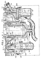
- the chamber 4 is of a substantially cylindrical shape (see Figure 8) and its lower portion is connected with a tubular union conduit 6 curved at an angle of about 90° and which, in turn is connected with a discharge conduit 13. Between the lower open end of the chamber 4 and the union conduit 6 is mounted a net 14 or other suitable perforated diaphragm adapted to separate the biggest residues which could obstruct the discharge conduit 13.
- the body forming the chamber 4 is mounted in the container 1 in any disassemblable manner so as to permit that the maintenance and overhauling operations as well as the substitution of the damaged parts thereof can be easily carried out.
- At the central portion of the chamber 4 open at least two nozzles 35 placed in substantially diametrally opposited positions and so oriented so as to deliver jets directed downwardly towards the axis X-X of the chamber 4 so as to can hit the instruments which will be introduced into the chamber 4, and which will lean on the filtering wall 14.
- Said nozzles 35 are fed by means of pipes 29, which by means of a three-way pipe fitting 27 are connected with a single pipe 30, to which by means of another three-way pipe fitting 28 are connected a pipe 31 conveying compressed air, supplied by an external air source (not shown), said pipe 31 being controlled by an electric valve 32, as well as a pipe 33 conveying pressurized water supplied by an external water source (not shown), in said pipe 33 being inserted a second electric valve (34). Normally the electrovalves 32 and 34 close.
- nozzles 35 Underneath the first series of nozzles 35 delivering the jets designed to wash the instruments and to remove therefrom the residues adherent thereto under the violent mechanical effect of the jets of pressurized air and water, delivered by the nozzles 35 and which strike with force against the instrument, other nozzles 26 are mounted adapted to deliver jets in part inclined downwardly towards the axis X-X and in part directed radially.
- the nozzles 26 have the task of delivering air with an addition of a disinfectant medium, which is produced into a nebulizer 9 and is supplied through the pipe 23.
- annular band 17 For such a purpose about the side wall of the chamber 4 and underneath the nozzles 35 an annular band 17, is mounted, in which an annular manifold 15 is arranged ( Figure 8) through which the nozzles 26 are fed, which deliver pressurized air jets dragging together particles of the disinfectant medium which is conveyed into the manifold 15 by the pipe 23 connected to the outlet 24 of the unit 9 ( Figure 5).
- the nozzles 26 produce jets which are in part radially directed and in part downwardly directed towards the axis X-X said jets having as first task that of creating a downwards suction effect of the drops which can be produced, as a result of the impact-of the jets delivered by the nozzles 35 against the instrument, and, as a second and main task, that of carrying out the drying up and the disinfection of the instrument after its washing.
- the device is so programmed that the jets coming out of the nozzles 26 are delivered during a predetermined time interval which is greater than that of the jets of the nozzles 35; i.e. the jets delivered by the nozzles 26 continue to be dispensed also after the jets of nozzles 35 stop.
- the nebulizing 9 is of the type already described and shown in the first embodiment.
- it comprises an inner chamber from the upper part of which through the already mentioned pipe union 23 the air with the addition of the disinfectant medium is delivered, said pressurized air with the disinfectant medium being obtained, supplying compressed air into the nebulizer 9 through a pipe 16 connected with an external air source (not shown), said pressurized air entering the unit 9 through a pipe (which is not shown in the Figures 5 to 9) which opens near the bottom of said inner chamber which contains the disinfectant medium which will be charged through a pipe union closed by the plug 7.
- the pipe 16 ( Figure 6) receives the air by means of a pipe 18 in which is provided the third electric valve 38 which normally closes, said pipe 18 being connected to the pipe 16 by means of a four-way pipe fitting 10 from which are branched off the said pipe 16 as well as the pipes 11 and 12 which serve to convey the pressurized air to a device generally indicated 20 mounted on the discharge pipe 13 of the dirty water.
- Said unit 20 comprises a pipe length 21 connected to the pipe 13, in which a conduit 22 is arranged in which a nozzle 19 is mounted delivering pressurized air conveyed by the pipe 12, the said nozzle being oriented in the same direction of the flow of the dirty water, thus creating a suction effect which makes easier the discharge of the dirty water from the treatment chamber 4.
- the device 20 comprises an inner cylindrical chamber, the bottom of which is connected by a funnel-like portion with the outlet pipe union 25, while an inclined partition wall or screen 36 deviates downwardly the water flow which arrives through the inlet conduit 50 connected to the pipe length 21, said water flow thus entering the chamber of the unit 20 at its upper part, while through the top wall of said inner chamber of the unit 20 behind the screen 36 an outlet orifice 37 is provided for the discharge of the air through an air discharge pipe 51.
- the supply line which by means of the terminals 43 will be connected with a source of electric current.
- a transformer 45 is inserted, said line 44 being connected to the block 40 which represents a programmer and actuator, comprising logical circuits which become operative under the consent of the photo-electric cells 3a, 3b when the barrage rays of the entrance opening 2 of the chamber 4 will be interrupted by the introduction of the instrument to be cleaned.
- Said logical circuits are designed to cause the opening of the electro-valves 32, 34, 38.
- the electric valves 32, 34 and 36 are caused to be opened so that the nozzles 35 will deliver strong jets of air and water, which carry out the cleaning (of the instrument) from which will be removed the possible materials which can be adhered to the instrument, while the series of jets of air and disinfectant will be delivered from the nozzles 26 in the first phase serve only for creating a suction effect towards the discharge conduit of the water drops which can,be formed, thus preventing that said water drops can escape outside through the entrance opening 2.
- the logical circuits are so programmed that the valves 32 and 34 are maintained in their open position for a time interval less that of the valve 38.
- valves 32 and 34 are maintained in their open condition for about 5 seconds while the valve 38 remains in its opened position for about 20 seconds, thus after about 5 seconds the jets produced by the nozzles 35 stop, while the delivery of the air added with disinfectant through the nozzles 26 continues during further 15 seconds so as to permit to obtain the drying and disinfection of the instrument.
- the valve 38 closes and the instrument can be removed perfectly cleaned by means of the device and with the lowest consumption of water, air and electric energy.
- valve 34 can be eliminated, so as to maintain the sole valve 32 controlling the supply of the pressurized air.
- the water flow will be guided so as to join with the compressed air flow conveyed by the supply pipe with the interposition of an already known spraying unit which will serve as a mean of compensation for any change of pressure of the water-air mixture which will be formed into said unit and which will be conveyed into the pipes 30 and then into the pipes 29 feeding the nozzles 35, as has been hereinbefore described.
- the third embodiment can be considered a combination of the two preceding solutions but it is, in particular a variant of the second embodiment, while from the first one only the characteristic rises that in the single washing chamber 204, upstream of the nozzles 35 delivering the washing jets, a series of nozzles 213, 213a is also provided, said nozzles delivering air containing a disinfectant medium so as to create a barrage or screen which prevents any escape of water drops from the chamber 204, while in the same time carries out a first disinfection of the instruments.
- 102 indicates a group to which are connected the pipe 220 conveying the air and the pipe 230 conveying the water respectively; 40 is the programmer and 9 the nebulizer provided for producing the air incorporating the disinfectant medium, which will be charged through a pipe union closed by the plug 7.
- the treatment chamber 204 has a frusto-conical shaped tapered upwardly and provided with an entrance opening 2 controlled by at least a photo-electric cell 3a, 3b, inserted in the circuit 5, as described in the second embodiment.
- the photo-electric cell 3a, 3b controls the starting of the programmer 40.
- the lower end of the chamber 204 is yet closed by a filtering grating 14 and is put in communication with the discharge conduit 13.
- Underneath the entrance opening 2 are provided two crowns of nozzles 213 and 213a which have skew axes with respect of the axis X-X of the chamber 204 so as to deliver sub-tangential jets which are also inclined downwardly.
- the inclination of the jets of the second crown of jets 213a is greater than that of the first crown 213.
- Said nozzles 213 and 213a receive air added with a disinfectant medium, which is conveyed into the manifold 212 and which is fed by the pipes 224a and 224, from the unit 9 which is operatively identical to the units 9 of the two preceding embodiments.
- the nozzles 35 Downstream of the nozzles 213, 213a which have the task of carrying out the first disinfection of the instrument and at the same time of creating a barrage against the escape of water drops, as has been provided in the first embodiment, are provided the nozzles 35 which have tasks, and dispositions identical to those of the nozzles 35 of the two preceding embodiments and which are fed by air and water which are conveyed by the pipes 227a, 227 and 233a and 233 respectively.
- the pipe 227 is controlled by the electric valve 32 and the pipe 233 by the electric valve 34.
- the feeding pipe 220 of the air is connected to the valve 32 by the pipe 225 and the outlet orifice of this valve is connected to the nozzles 35 by the pipes 227, 227a, 227b while the same supply pipe 220 by means of the pipe 221 is connected to the electric valve 38 which is, in turn, connected to the nebulizer 9 by means of the pipe 223.
- the atomizer produces a flow of air containing a disinfectant medium, said air flow by means of the pipes 224 and 224a is conveyed to the first system of nozzles 213 and 213a, and by means of the pipes 224, 224b is conveyed to the second series of nozzles 226 mounted below the washing nozzles 35 and having the same task and disposition as those of the nozzles 26 provided in the second embodiment.
- the main water supply pipe 230 is connected to the electric valve 34 by the pipe 231, the outlet orifice of said valve is connected by the pipes 233, 233a, 223b to the nozzles 35.
- FIG. 11 shows the flow diagram of the air and water circuits of this third embodiment.
- This third embodiment will be not furtherly described and illustrated, since it is operatively identical to the preceding one.
Landscapes
- Health & Medical Sciences (AREA)
- Oral & Maxillofacial Surgery (AREA)
- Dentistry (AREA)
- Epidemiology (AREA)
- Life Sciences & Earth Sciences (AREA)
- Animal Behavior & Ethology (AREA)
- General Health & Medical Sciences (AREA)
- Public Health (AREA)
- Veterinary Medicine (AREA)
- Dental Tools And Instruments Or Auxiliary Dental Instruments (AREA)
- Apparatus For Disinfection Or Sterilisation (AREA)
- Brushes (AREA)
Claims (10)
Priority Applications (1)
| Application Number | Priority Date | Filing Date | Title |
|---|---|---|---|
| AT82830003T ATE29846T1 (de) | 1981-01-06 | 1982-01-06 | Reinigungsvorrichtung fuer zahninstrumente, insbesondere turbinenbohrer und dergleichen. |
Applications Claiming Priority (2)
| Application Number | Priority Date | Filing Date | Title |
|---|---|---|---|
| IT47521/81A IT1142212B (it) | 1981-01-06 | 1981-01-06 | Dispositivo per la pulizia di strumenti odontoiatrici in particolare trapani a turbina o simili |
| IT4752181 | 1981-01-06 |
Publications (3)
| Publication Number | Publication Date |
|---|---|
| EP0056791A2 EP0056791A2 (fr) | 1982-07-28 |
| EP0056791A3 EP0056791A3 (en) | 1983-01-26 |
| EP0056791B1 true EP0056791B1 (fr) | 1987-09-23 |
Family
ID=11260847
Family Applications (1)
| Application Number | Title | Priority Date | Filing Date |
|---|---|---|---|
| EP82830003A Expired EP0056791B1 (fr) | 1981-01-06 | 1982-01-06 | Dispositif de nettoyage pour instruments dentaires, spécialement pour des forets à turbine et similaires |
Country Status (4)
| Country | Link |
|---|---|
| EP (1) | EP0056791B1 (fr) |
| AT (1) | ATE29846T1 (fr) |
| DE (1) | DE3277367D1 (fr) |
| IT (1) | IT1142212B (fr) |
Families Citing this family (12)
| Publication number | Priority date | Publication date | Assignee | Title |
|---|---|---|---|---|
| FR2618357B1 (fr) * | 1987-07-24 | 1990-02-23 | Micro Mega Sa | Appareil automatique pour le nettoyage des pieces a main de dentisterie |
| FR2641973B1 (fr) * | 1989-01-20 | 1991-04-19 | Bene Pierre Yves | Dispositif de nettoyage et de desinfection d'instruments medicaux et chirurgicaux |
| DE69324796D1 (de) * | 1992-01-21 | 1999-06-10 | Strathayr Pty Ltd | Handhabungssystem für rasen |
| DE69605548T2 (de) * | 1995-06-13 | 2000-07-13 | Bitiess Microtecnica S.A., Barbengo | Universalgerät zur gründlichen reinigung, desinfektion und sterilisation von zahnärtzlichen, chirurugischen und tierärtzlichen instrumentn sowie zu anderen anwendungen |
| RU2212286C2 (ru) * | 2001-05-18 | 2003-09-20 | Открытое акционерное общество "Уральский научно-исследовательский технологический институт" | Линия мойки и сушки труб |
| FR2958852B1 (fr) | 2010-04-14 | 2012-06-01 | Nnie Plus | Dispositif automatique de desinfection de moteurs chirurgicaux. |
| IT202100006911A1 (it) | 2021-03-23 | 2022-09-23 | Cefla Soc Cooperativa | Dispositivo per lubrificazione e opzionalmente detersione e disinfezione di manipoli odontoiatrici |
| IT202100006899A1 (it) | 2021-03-23 | 2022-09-23 | Cefla Soc Cooperativa | Dispositivo per lubrificazione e opzionalmente detersione e disinfezione di manipoli odontoiatrici |
| IT202100006902A1 (it) | 2021-03-23 | 2022-09-23 | Cefla Soc Cooperativa | Dispositivo per lubrificazione e opzionalmente detersione e disinfezione di manipoli odontoiatrici |
| CN114306681B (zh) * | 2021-12-25 | 2023-04-11 | 提技贸易(上海)有限公司 | 一种管道自动消毒系统及方法 |
| DE202022101511U1 (de) | 2022-03-22 | 2022-06-21 | Cefla Societa' Cooperativa | Vorrichtung zum Schmieren und optional Reinigen und Desinfizieren von zahnärztlichen Handstücken |
| DE202022101512U1 (de) | 2022-03-22 | 2022-06-21 | Cefla Societa' Cooperativa | Vorrichtung zum Schmieren und optional Reinigen und Desinfizieren von zahnärztlichen Handstücken |
Family Cites Families (3)
| Publication number | Priority date | Publication date | Assignee | Title |
|---|---|---|---|---|
| DE2805934A1 (de) * | 1977-02-23 | 1978-08-24 | Doppler Geb Redtenbacher Elisa | Zahnaerztliches geraet |
| DE2836532C2 (de) * | 1978-08-21 | 1984-09-13 | Hans Dr.med. Dr.med.dent. 8000 München Scheicher | Verfahren und Vorrichtung zum Sterilhalten chirurgischer oder zahnärztlicher Handstücke |
| JPS5596131A (en) * | 1979-01-17 | 1980-07-22 | Olympus Optical Co | Endoscope washer |
-
1981
- 1981-01-06 IT IT47521/81A patent/IT1142212B/it active
-
1982
- 1982-01-06 DE DE8282830003T patent/DE3277367D1/de not_active Expired
- 1982-01-06 EP EP82830003A patent/EP0056791B1/fr not_active Expired
- 1982-01-06 AT AT82830003T patent/ATE29846T1/de not_active IP Right Cessation
Also Published As
| Publication number | Publication date |
|---|---|
| IT1142212B (it) | 1986-10-08 |
| EP0056791A2 (fr) | 1982-07-28 |
| ATE29846T1 (de) | 1987-10-15 |
| IT8147521A0 (it) | 1981-01-06 |
| DE3277367D1 (en) | 1987-10-29 |
| EP0056791A3 (en) | 1983-01-26 |
Similar Documents
| Publication | Publication Date | Title |
|---|---|---|
| US4552163A (en) | Cleaning device for dental instruments to be used during surgery and dental treatments | |
| US3882638A (en) | Air-abrasive prophylaxis equipment | |
| JPS59156341A (ja) | 歯の掃除装置及び方法 | |
| US5593304A (en) | Dental apparatus including multiple-use electrically-oscillated handpiece | |
| US5571488A (en) | Apparatus for the hygienic preparation of medical instruments | |
| EP0056791A2 (fr) | Dispositif de nettoyage pour instruments dentaires, spécialement pour des forets à turbine et similaires | |
| US3972123A (en) | Air-abrasive prophylaxis equipment | |
| US4382424A (en) | Automatic apparatus for cleaning dogs and similar animals | |
| EP0127380B1 (fr) | Instrument d'irrigation endodontique | |
| US5543119A (en) | Cassette for treating medical instruments | |
| US3164153A (en) | Dental apparatus | |
| US5094615A (en) | Dental polishing head and method | |
| AU730692C (en) | A method of cleaning a filter unit, and a filter unit for filtering gas | |
| US4857112A (en) | Method and apparatus for cleaning a pipe system provided for the operation of baths | |
| US5193563A (en) | Surgical suite scrub station | |
| US5295828A (en) | Apparatus for filling tooth root canals under vacuum | |
| EP0338607B1 (fr) | Système d'hydromassage autonettoyant pour baignoires | |
| GB2026359A (en) | Apparatus for delivering a stream of abrasive material for cleaning teeth | |
| US2813529A (en) | Tooth cleansing devices | |
| JPH07222757A (ja) | 歯の予防処置及び水保存用の装置 | |
| DE102017208430A1 (de) | Reinigungsgerät zur Reinigung oder Desinfektion von Gegenständen | |
| US5951511A (en) | Colon cleansing apparatus and method | |
| CN219090019U (zh) | 一种便于使用的牙椅 | |
| EP0034123A2 (fr) | Appareil de lavage automatique pour chiens et animaux similaires | |
| EP0679406B1 (fr) | Méthode et dispositif de nettoyage des instruments médicaux, paramédicaux et dentaires et de leur conduites |
Legal Events
| Date | Code | Title | Description |
|---|---|---|---|
| PUAI | Public reference made under article 153(3) epc to a published international application that has entered the european phase |
Free format text: ORIGINAL CODE: 0009012 |
|
| AK | Designated contracting states |
Designated state(s): AT BE CH DE FR GB IT LI LU NL SE |
|
| PUAL | Search report despatched |
Free format text: ORIGINAL CODE: 0009013 |
|
| AK | Designated contracting states |
Designated state(s): AT BE CH DE FR GB IT LI LU NL SE |
|
| 17P | Request for examination filed |
Effective date: 19830725 |
|
| RAP1 | Party data changed (applicant data changed or rights of an application transferred) |
Owner name: MEDICAL ENGINEERING CONSULTING GRIFO SA Owner name: VOEST-ALPINE WERKZEUGE UND PRAEZISIONSTECHNIK GES |
|
| GRAA | (expected) grant |
Free format text: ORIGINAL CODE: 0009210 |
|
| AK | Designated contracting states |
Kind code of ref document: B1 Designated state(s): AT BE CH DE FR GB IT LI LU NL SE |
|
| REF | Corresponds to: |
Ref document number: 29846 Country of ref document: AT Date of ref document: 19871015 Kind code of ref document: T |
|
| REF | Corresponds to: |
Ref document number: 3277367 Country of ref document: DE Date of ref document: 19871029 |
|
| ITF | It: translation for a ep patent filed | ||
| REG | Reference to a national code |
Ref country code: CH Ref legal event code: PUE Owner name: MEDICAL ENGINEERING CONSULTING GRIFO SA |
|
| PG25 | Lapsed in a contracting state [announced via postgrant information from national office to epo] |
Ref country code: LU Free format text: LAPSE BECAUSE OF NON-PAYMENT OF DUE FEES Effective date: 19880131 |
|
| ET | Fr: translation filed | ||
| NLS | Nl: assignments of ep-patents |
Owner name: MEDICAL ENGINEERING CONSULTING GRIFO S.A. TE BARBE |
|
| PLBE | No opposition filed within time limit |
Free format text: ORIGINAL CODE: 0009261 |
|
| STAA | Information on the status of an ep patent application or granted ep patent |
Free format text: STATUS: NO OPPOSITION FILED WITHIN TIME LIMIT |
|
| 26N | No opposition filed | ||
| REG | Reference to a national code |
Ref country code: GB Ref legal event code: 732 |
|
| REG | Reference to a national code |
Ref country code: GB Ref legal event code: 732 |
|
| PGFP | Annual fee paid to national office [announced via postgrant information from national office to epo] |
Ref country code: LU Payment date: 19900123 Year of fee payment: 9 |
|
| REG | Reference to a national code |
Ref country code: FR Ref legal event code: ST |
|
| REG | Reference to a national code |
Ref country code: FR Ref legal event code: R1 |
|
| PGFP | Annual fee paid to national office [announced via postgrant information from national office to epo] |
Ref country code: GB Payment date: 19940126 Year of fee payment: 13 |
|
| ITTA | It: last paid annual fee | ||
| REG | Reference to a national code |
Ref country code: FR Ref legal event code: D1 |
|
| PG25 | Lapsed in a contracting state [announced via postgrant information from national office to epo] |
Ref country code: GB Effective date: 19950106 |
|
| EAL | Se: european patent in force in sweden |
Ref document number: 82830003.8 |
|
| GBPC | Gb: european patent ceased through non-payment of renewal fee |
Effective date: 19950106 |
|
| PGFP | Annual fee paid to national office [announced via postgrant information from national office to epo] |
Ref country code: NL Payment date: 19960731 Year of fee payment: 15 Ref country code: AT Payment date: 19960731 Year of fee payment: 15 Ref country code: SE Payment date: 19960731 Year of fee payment: 15 Ref country code: BE Payment date: 19960731 Year of fee payment: 15 Ref country code: FR Payment date: 19960731 Year of fee payment: 15 |
|
| PGFP | Annual fee paid to national office [announced via postgrant information from national office to epo] |
Ref country code: CH Payment date: 19960805 Year of fee payment: 15 |
|
| PGFP | Annual fee paid to national office [announced via postgrant information from national office to epo] |
Ref country code: DE Payment date: 19960930 Year of fee payment: 15 |
|
| PG25 | Lapsed in a contracting state [announced via postgrant information from national office to epo] |
Ref country code: AT Effective date: 19970106 |
|
| PG25 | Lapsed in a contracting state [announced via postgrant information from national office to epo] |
Ref country code: SE Effective date: 19970107 |
|
| PG25 | Lapsed in a contracting state [announced via postgrant information from national office to epo] |
Ref country code: BE Effective date: 19970131 Ref country code: LI Effective date: 19970131 Ref country code: CH Effective date: 19970131 |
|
| BERE | Be: lapsed |
Owner name: MEDICAL ENGINEERING CONSULTING GRIFO S.A. Effective date: 19970131 Owner name: VOEST-ALPINE WERKZEUGE UND PRAZISIONSTECHNIK G.M. Effective date: 19970131 |
|
| PG25 | Lapsed in a contracting state [announced via postgrant information from national office to epo] |
Ref country code: NL Effective date: 19970801 |
|
| REG | Reference to a national code |
Ref country code: CH Ref legal event code: PL |
|
| PG25 | Lapsed in a contracting state [announced via postgrant information from national office to epo] |
Ref country code: FR Effective date: 19970930 |
|
| NLV4 | Nl: lapsed or anulled due to non-payment of the annual fee |
Effective date: 19970801 |
|
| PG25 | Lapsed in a contracting state [announced via postgrant information from national office to epo] |
Ref country code: DE Effective date: 19971001 |
|
| EUG | Se: european patent has lapsed |
Ref document number: 82830003.8 |
|
| REG | Reference to a national code |
Ref country code: FR Ref legal event code: ST |