EP0056813B1 - Kontrollsystem für die dampfabgabe - Google Patents
Kontrollsystem für die dampfabgabe Download PDFInfo
- Publication number
- EP0056813B1 EP0056813B1 EP81902173A EP81902173A EP0056813B1 EP 0056813 B1 EP0056813 B1 EP 0056813B1 EP 81902173 A EP81902173 A EP 81902173A EP 81902173 A EP81902173 A EP 81902173A EP 0056813 B1 EP0056813 B1 EP 0056813B1
- Authority
- EP
- European Patent Office
- Prior art keywords
- working fluid
- steam
- heat exchanger
- superheater
- evaporator
- Prior art date
- Legal status (The legal status is an assumption and is not a legal conclusion. Google has not performed a legal analysis and makes no representation as to the accuracy of the status listed.)
- Expired
Links
Images


Classifications
-
- F—MECHANICAL ENGINEERING; LIGHTING; HEATING; WEAPONS; BLASTING
- F02—COMBUSTION ENGINES; HOT-GAS OR COMBUSTION-PRODUCT ENGINE PLANTS
- F02C—GAS-TURBINE PLANTS; AIR INTAKES FOR JET-PROPULSION PLANTS; CONTROLLING FUEL SUPPLY IN AIR-BREATHING JET-PROPULSION PLANTS
- F02C3/00—Gas-turbine plants characterised by the use of combustion products as the working fluid
- F02C3/20—Gas-turbine plants characterised by the use of combustion products as the working fluid using a special fuel, oxidant, or dilution fluid to generate the combustion products
- F02C3/30—Adding water, steam or other fluids for influencing combustion, e.g. to obtain cleaner exhaust gases
-
- F—MECHANICAL ENGINEERING; LIGHTING; HEATING; WEAPONS; BLASTING
- F01—MACHINES OR ENGINES IN GENERAL; ENGINE PLANTS IN GENERAL; STEAM ENGINES
- F01K—STEAM ENGINE PLANTS; STEAM ACCUMULATORS; ENGINE PLANTS NOT OTHERWISE PROVIDED FOR; ENGINES USING SPECIAL WORKING FLUIDS OR CYCLES
- F01K21/00—Steam engine plants not otherwise provided for
- F01K21/04—Steam engine plants not otherwise provided for using mixtures of steam and gas; Plants generating or heating steam by bringing water or steam into direct contact with hot gas
- F01K21/047—Steam engine plants not otherwise provided for using mixtures of steam and gas; Plants generating or heating steam by bringing water or steam into direct contact with hot gas having at least one combustion gas turbine
-
- F—MECHANICAL ENGINEERING; LIGHTING; HEATING; WEAPONS; BLASTING
- F22—STEAM GENERATION
- F22B—METHODS OF STEAM GENERATION; STEAM BOILERS
- F22B35/00—Control systems for steam boilers
- F22B35/007—Control systems for waste heat boilers
-
- F—MECHANICAL ENGINEERING; LIGHTING; HEATING; WEAPONS; BLASTING
- F22—STEAM GENERATION
- F22B—METHODS OF STEAM GENERATION; STEAM BOILERS
- F22B35/00—Control systems for steam boilers
- F22B35/06—Control systems for steam boilers for steam boilers of forced-flow type
-
- Y—GENERAL TAGGING OF NEW TECHNOLOGICAL DEVELOPMENTS; GENERAL TAGGING OF CROSS-SECTIONAL TECHNOLOGIES SPANNING OVER SEVERAL SECTIONS OF THE IPC; TECHNICAL SUBJECTS COVERED BY FORMER USPC CROSS-REFERENCE ART COLLECTIONS [XRACs] AND DIGESTS
- Y02—TECHNOLOGIES OR APPLICATIONS FOR MITIGATION OR ADAPTATION AGAINST CLIMATE CHANGE
- Y02E—REDUCTION OF GREENHOUSE GAS [GHG] EMISSIONS, RELATED TO ENERGY GENERATION, TRANSMISSION OR DISTRIBUTION
- Y02E20/00—Combustion technologies with mitigation potential
- Y02E20/14—Combined heat and power generation [CHP]
Definitions
- This invention relates to a dual working fluid heat engine which comprises a compressor for compressing air, a combustion chamber fed by said compressor for combustion of the air with a fuel directly introduced into said combustion chamber, thus forming the first working fluid, means for injecting a second working fluid into said combustion chamber, a core turbine receiving the exhaust gases, being a mixture of said first working fluid and said second working fluid, from said combustion chamber and driving said compressor, a work turbine, receiving the exhaust gases from said core turbine, and a counterflow heat exchanger, receiving the exhaust gases from said work turbine and the second working fluid for heating the second working fluid from its liquid state into superheated steam which is injected into said combustion chamber by said means, said counterflow heat exchanger comprising an evaporator and a superheater section, if fuel combustion is the source of energy for the gas turbine, or which comprises a compressor for compressing a first working fluid, a primary heat exchanger receiving the first working fluid from said compressor and heating said first working fluid using solar energy or nuclear energy, means for injecting a second working fluid into the flow
- the steam from the counterflow heat exchanger flows through a control valve at the outlet from the superheater. It is traditional that the steam control valve is located at the output end of the boiler. This control valve normally controls the rate of steam flow.
- this object is achieved by locating a single control valve between said evaporator and said superheater sections of said counterflow heat exchanger for regulating the steam generation rate.
- the exit of the superheater section is preferably directly connected to the combustion chamber mixing the superheated steam with the combustion products.
- the evaporator section includes a liquid storage drum, and a co-generation valve is provided to allow high pressure steam to be drawn from said liquid storage drum for co-generation purposes.
- FIG. 1 is a block diagram of one embodiment of a Cheng dual-fluid cycle heat engine 10.
- the engine typically uses air as the first working fluid. Fuel combustion with the air is a typical source of energy, and water is a typical second working fluid. Air enters a compressor 14 at 12 where it is adiabatically compressed.
- the first working fluid can be heated in other ways besides combustion; for example, by solar energy or nuclear energy in combination with a heat exchanger in place of the combustor (see. e.g. US-A-4128 994). For the remainder of this description, it is assumed that the first working fluid is heated by combustion.
- Water the second working fluid, is compressed to a high pressure by pump 22.
- the high pressure water enters waste heat boiler or regenerator 30 where waste exhaust heat is absorbed from the steam/combustion product mixture exhausted from the expander 28. There the water is heated to superheated vapor. Because of the latent heat of evaporation of water, much of the heat absorbed by any water converted- to steam is absorbed at essentially constant temperature, i.e. boiling temperature.
- the super-heated steam from the regenerator 30 then enters the combustion chamber 16 where it is mixed with the combustion products through turbulent mixing.
- the amount of superheated steam provided to the combustion chamber 16 is regulated by control valve 44.
- the mixture of the two working fluids then enters an expander or core turbine 26, which drives the compressor 14, then enters another expander or work turbine 28.
- These expanders convert the thermal energy of the two working fluids into mechanical work, to drive the compressor 14 and to produce net work output.
- Waste heat boiler 30 is a counter flow heat exchanger used to regenerate the waste heat from the cycle.
- the gas side of the heat exchanger contains the gas mixture which drops in temperature from the power turbine 28 discharge to a temperature at or above the saturation temperature of the water in the gas mixture. This saturation temperature is a function of the partial pressure of the steam in the gas mixture.
- water under pressure is heated from approximately ambient temperature to super-heated steam. From the heat exchanger the gas mixture is discharged into condenser 29 or vented.
- the proper amount of water is metered and pumped to the liquid side of the heat exchanger for regeneration ahead of the combustor.
- the remaining water is passed through a cooling tower or other cooling means and then reused in the condenser.
- the prior Cheng cycle patent defines the peak operating condition cycle parameters to design an engine for 100 percent load. Because of the parallel combined nature of the Brayton and Rankine cycles in this engine, the quantity and quality of steam that can be generated by a given engine configuration can be varied freely over a range.
- the control path for the steam cycle is essentially independent of that for the gas turbine cycle.
- the control path for throttling the engine is essentially free or undefined.
- FIG. 2 illustrates a typical waste heat boiler 30. It is made up of three sections, an economizer 32, an evaporator 34, and a superheater 36.
- Feedwater pump 38 drives water into the economizer. Since liquid water is almost an incompressible fluid, water pump 38 does not have to do much work to pressurize the water.
- Steam is produced in the evaporator 34, and then further heated in the superheater 36, by exhaust gases which have exited from the turbine in the DFC engine 10. In Figure 2 the exhaust gases pass from left to right.
- Within the evaporator section 34 is a water storage drum 40 and a recirculating water pump 42 to increase liquid side flow velocity and to reduce the vapor-to-liquid ratio at the optimum heat transfer condition.
- Steam pressure is controlled in part by the heat transfer surface area, by a control valve, and, if excessive, by a blowoff valve (not shown).
- a control valve To convert steam energy into mechanical energy, steam should be fed into an energy converting device at the highest temperature and pressure economically possible for a given boiler design. Therefore, typically, the control valve 44 is mounted at the outlet of the boiler; that is at the superheater 30 outlet.
- the rate of steam flow is throttled back by the control valve 44.
- the steam turbine operates at a constant RPM; therefore, a governor control will be used ordinarily to keep the steam turbine at a constant RPM.
- the waste heat boiler designed for a dual fluid cycle engine to recover waste heat from the turbine exhaust operates at a very critical steam- to-air flow ratio.
- the steam In order to control the partial load of the turbine so as to reach all the peak steam-air flow ratio conditions, the steam must not only be critically metered according to the load, but it must be at the highest super heat condition. This becomes a very difficult task for the ordinary boiler steam control, as shown in Figure 2, because the thermal lag involved in the boiler system with such a large heated mass retards the response when more steam is needed. Conversely, the thermal inertia slows down the response to reduced load because the stored thermal energy in the steam has to be dissipated.
- FIG 3 shows an improved waste heat boiler 30' which is the waste heat boiler 30 of Figure 2 but with a steam control valve 44' located between the evaporator 34 and superheater 36 sections instead of at the output of the superheater 36.
- This valve location enables the superheater to achieve high superheat and facilitates operating on the peak efficiency points of a dual fluid cycle engine. Throttling the control valve 44' causes the boiler pressure in the evaporator to be higher. Ordinarily, the design surface areas of the boiler sections are determined by the maximum (design) power operating conditions. At this point heat transfer has to be balanced out through all three sections of the heat exchanger 30.
- a steam valve located at the outlet of the superheater as shown in Figure 2 does not give the steam conditions needed to operate a dual fluid cycle engine at peak efficiency at partial load.
- the boiler evaporator section pressure is higher under throttled conditions in spite of the fact that the area of the evaporator is excessive to the steaming requirements of throttled operation.
- the steaming rate is reduced by the reduced temperature difference between the heat transfer media and the steam control valve provides a self- adjusting heat transfer mechanism by means of the pressure drop used to control the steam flow rate.
- Throttling can be immediate simply by throttling back the steam, thus causing the pressure in the evaporator to build up.
- higher pressure steam is available as stored in the drum to give an instantaneous steam supply without the addition of heat momentarily to the superheater; concurrently, additional exhaust gas heat from the engine increases the temperature of the steam in the superheater to provide the appropriate degree of superheat for high efficiency operating conditions.
- a valve 45 allows steam to be drawn from drum 40 at high pressure, which is most useful for co-generation purposes. At the same time the remaining steam, at lower pressure, can still be heated by the turbine exhaust gas in the superheater section 36 to its highest enthalpy, only limited by the surface area of the superheater and thermodynamic constraints.
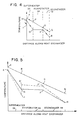
- Figure 4 shows the temperature profile across the waste heat boiler 30 of Figure 2.
- the lower curve is the temperature of the water/steam as it passes from right to left through the boiler 30.
- the temperature of the exhaust gas from the DFC engine turbine is the top curve. The gas moves from left to right in Figure 4.
- the temperatures designated in Figure 4 are:
- the superheated steam temperature drops to 475°F (246°C), state I.
- the temperature also drops from state G to state J because of the throttling effect of control valve 44'.
- the steam is eventually heated up to the desired temperature of 520°F (271°C) at state K.
- the temperature of the superheated steam is 45°F (25°C) higher and the waste heat boiler 30 of Figure 4 recovers 25 Btu/Ib (58,1 kj/kg) more waste heat enthalpy than otherwise.
- the initial temperature drop from state G to J helps to increase the log means temperature difference, hence does not require excessive surface area of the superheater 36.
- the Cheng DFC engine utilizes steam at very high temperatures at highly superheated states. If the DFC has a turbine inlet temperature of 2150°F (1177°C), and a compression ratio of 18 to 1, the turbine exhaust gas temperature will be on the order of 1000°F (538°C) or more. The desired steam temperature before the injection into the combustion chamber will be on the order of 959°F (515°C). At that temperature, a steam control valve has to use high temperature materials such as stainless steel. The size of the valve is large because the specific volume of the steam at high temperature is large.
- the steam control valve 36 throttles the steam in the neighborhood of steam saturation temperature so the material requirement is relaxed plus the specific volume is relatively small. Hence a smaller physical size of the throttle valve can be used. This reduces the cost and maintenance of the control system.
- This new invention also changes the characteristics of the boiler system.
- the response time of the boiler to produce steam is very slow, due to its large mass, i.e., thermal inertia.
- the boiler generally has excess surface area in the evaporator 34.
- the conventional control allows hot water to be wasted through a slow-down process or by bleeding steam for cogeneration.
- the boiler requires a time lag to come up with the right amount of steam.
- the temperature profile self limits the heat transfer to the evaporator.
- the high pressure steam stored in the drum stores high quality thermal energy, in the form of high energy containing steam, which can be tapped by opening up the control valve 44' instead of waiting for the slow steam build up due to thermal lag. This cuts down the response time of the dual fluid cycle engine by a large margin such that rapid acceleration and fast response time is obtained without overheating the engine components.
- the prior art has a control valve at the outlet of the waste heat boiler.
- the superheater has the same pressure as the steam drum.
- the boiler operates at approximately constant pressure in the evaporator sections.
- the present invention has a control valve between the evaporator and superheater.
- the pressure in the drum is used as an energy storage system to adjust the evaporator temperature difference between the exhaust gases and the steam.
- This control system has rapid response for steam supply. It also provides maximum superheat temperatures available to provide the steam quality required for efficient operation of a DFC engine system.
Landscapes
- Engineering & Computer Science (AREA)
- Chemical & Material Sciences (AREA)
- Combustion & Propulsion (AREA)
- Mechanical Engineering (AREA)
- General Engineering & Computer Science (AREA)
- Physics & Mathematics (AREA)
- Thermal Sciences (AREA)
- Engine Equipment That Uses Special Cycles (AREA)
- Control Of Steam Boilers And Waste-Gas Boilers (AREA)
Claims (4)
Applications Claiming Priority (2)
| Application Number | Priority Date | Filing Date | Title |
|---|---|---|---|
| US06/175,287 US4393649A (en) | 1979-07-23 | 1980-08-04 | Steam output control system |
| US175287 | 1980-08-04 |
Publications (3)
| Publication Number | Publication Date |
|---|---|
| EP0056813A1 EP0056813A1 (de) | 1982-08-04 |
| EP0056813A4 EP0056813A4 (de) | 1984-02-07 |
| EP0056813B1 true EP0056813B1 (de) | 1988-06-29 |
Family
ID=22639702
Family Applications (1)
| Application Number | Title | Priority Date | Filing Date |
|---|---|---|---|
| EP81902173A Expired EP0056813B1 (de) | 1980-08-04 | 1981-08-04 | Kontrollsystem für die dampfabgabe |
Country Status (6)
| Country | Link |
|---|---|
| US (1) | US4393649A (de) |
| EP (1) | EP0056813B1 (de) |
| JP (1) | JPS57501136A (de) |
| DE (1) | DE3176801D1 (de) |
| IT (1) | IT1138885B (de) |
| WO (1) | WO1982000493A1 (de) |
Families Citing this family (17)
| Publication number | Priority date | Publication date | Assignee | Title |
|---|---|---|---|---|
| US4823546A (en) * | 1984-02-07 | 1989-04-25 | International Power Technology | Steam-injected free-turbine-type gas turbine |
| US4597256A (en) * | 1985-04-16 | 1986-07-01 | International Power Technology, Inc. | Method and apparatus for improved shutdown procedures in dual fluid Cheng cycle engines |
| US4735043A (en) * | 1985-07-08 | 1988-04-05 | International Power Technology | Method and apparatus for improved start-up procedures in conventional steam power generators and dual fluid Cheng cycle engines |
| US5170622A (en) * | 1991-04-02 | 1992-12-15 | Cheng Dah Y | Advanced regenerative parallel compound dual fluid heat engine Advanced Cheng Cycle (ACC) |
| US5233826A (en) * | 1991-04-02 | 1993-08-10 | Cheng Dah Y | Method for starting and operating an advanced regenerative parallel compound dual fluid heat engine-advanced cheng cycle (ACC) |
| DE19723543C2 (de) * | 1997-06-05 | 2003-04-17 | Deutsch Zentr Luft & Raumfahrt | Energieerzeugungsanlage |
| US6405521B1 (en) | 2001-05-23 | 2002-06-18 | General Electric Company | Gas turbine power augmentation injection system and related method |
| US6357218B1 (en) | 2001-06-20 | 2002-03-19 | General Electric Company | Steam generation system and method for gas turbine power augmentation |
| AR029828A1 (es) * | 2001-07-13 | 2003-07-16 | Petrobras En S A | Metodo para la regulacion primaria de frecuencia en turbinas de vapor de ciclo combinado |
| CA2497576A1 (en) * | 2002-07-14 | 2004-01-29 | Wolfgang Harazim | Method for the separation of residual gases and working fluid in a combined cycle water/steam process |
| GB2436128B (en) * | 2006-03-16 | 2008-08-13 | Rolls Royce Plc | Gas turbine engine |
| WO2007133071A2 (en) * | 2007-04-18 | 2007-11-22 | Nem B.V. | Bottom-fed steam generator with separator and downcomer conduit |
| JP6417167B2 (ja) * | 2014-09-29 | 2018-10-31 | 川崎重工業株式会社 | ガスタービン |
| JP6290063B2 (ja) | 2014-10-06 | 2018-03-07 | トクデン株式会社 | 過熱水蒸気生成装置 |
| US10947897B2 (en) * | 2015-04-17 | 2021-03-16 | Nostrum Energy Pte. Ltd. | Multiloop gas turbine system and method of operation thereof |
| JP6609180B2 (ja) * | 2015-12-24 | 2019-11-20 | 株式会社東芝 | プラント制御装置、プラント制御方法、および発電プラント |
| CN117108380B (zh) * | 2023-09-28 | 2025-08-26 | 西安热工研究院有限公司 | 一种回收联合循环机组燃机tca/fgh余热的orc系统 |
Citations (2)
| Publication number | Priority date | Publication date | Assignee | Title |
|---|---|---|---|---|
| US4072182A (en) * | 1977-01-05 | 1978-02-07 | International Power Technology, Inc. | Pressure staged heat exchanger |
| WO1981000280A1 (en) * | 1979-07-23 | 1981-02-05 | Int Power Tech | Control system for cheng dual-fluid cycle engine system |
Family Cites Families (8)
| Publication number | Priority date | Publication date | Assignee | Title |
|---|---|---|---|---|
| US2678531A (en) * | 1951-02-21 | 1954-05-18 | Chemical Foundation Inc | Gas turbine process with addition of steam |
| US2869323A (en) * | 1957-01-02 | 1959-01-20 | Gen Electric | Gas turbine power plant with steam injection |
| US3177659A (en) * | 1962-08-02 | 1965-04-13 | Westinghouse Electric Corp | Heat exchange apparatus |
| GB1269651A (en) * | 1969-02-14 | 1972-04-06 | British Nuclear Design Constr | Boiler systems for producing steam |
| US3978661A (en) * | 1974-12-19 | 1976-09-07 | International Power Technology | Parallel-compound dual-fluid heat engine |
| JPS5845566B2 (ja) * | 1978-05-10 | 1983-10-11 | 株式会社日立製作所 | 複合サイクル発電プラント |
| JPS5557608A (en) * | 1978-10-20 | 1980-04-28 | Hitachi Ltd | Control method of combined power plant and its device |
| US4248039A (en) * | 1978-12-06 | 1981-02-03 | International Power Technology, Inc. | Regenerative parallel compound dual fluid heat engine |
-
1980
- 1980-08-04 US US06/175,287 patent/US4393649A/en not_active Expired - Lifetime
-
1981
- 1981-07-28 IT IT23205/81A patent/IT1138885B/it active
- 1981-08-04 EP EP81902173A patent/EP0056813B1/de not_active Expired
- 1981-08-04 JP JP56502737A patent/JPS57501136A/ja active Pending
- 1981-08-04 WO PCT/US1981/000996 patent/WO1982000493A1/en not_active Ceased
- 1981-08-04 DE DE8181902173T patent/DE3176801D1/de not_active Expired
Patent Citations (2)
| Publication number | Priority date | Publication date | Assignee | Title |
|---|---|---|---|---|
| US4072182A (en) * | 1977-01-05 | 1978-02-07 | International Power Technology, Inc. | Pressure staged heat exchanger |
| WO1981000280A1 (en) * | 1979-07-23 | 1981-02-05 | Int Power Tech | Control system for cheng dual-fluid cycle engine system |
Also Published As
| Publication number | Publication date |
|---|---|
| EP0056813A1 (de) | 1982-08-04 |
| IT1138885B (it) | 1986-09-17 |
| WO1982000493A1 (en) | 1982-02-18 |
| EP0056813A4 (de) | 1984-02-07 |
| US4393649A (en) | 1983-07-19 |
| IT8123205A0 (it) | 1981-07-28 |
| DE3176801D1 (en) | 1988-08-04 |
| JPS57501136A (de) | 1982-07-01 |
Similar Documents
| Publication | Publication Date | Title |
|---|---|---|
| EP0056813B1 (de) | Kontrollsystem für die dampfabgabe | |
| US4128994A (en) | Regenerative parallel compound dual-fluid heat engine | |
| EP0034614B1 (de) | Steuerungssystem für einen cheng-gas-dampfturbinenprozess | |
| US5442908A (en) | Combined combustion and steam turbine power plant | |
| US4841722A (en) | Dual fuel, pressure combined cycle | |
| US5345755A (en) | Steam turbine plant | |
| US4248039A (en) | Regenerative parallel compound dual fluid heat engine | |
| US4753068A (en) | Gas turbine cycle incorporating simultaneous, parallel, dual-mode heat recovery | |
| US3006146A (en) | Closed-cycle power plant | |
| KR20010015055A (ko) | 연료 가스의 가습 및 가열용 방법과 장치 | |
| US4680927A (en) | Control system for Cheng dual-fluid cycle engine system | |
| JPS61234232A (ja) | ガスタ−ビン機関とガスタ−ビンを修正する方法 | |
| JPS61501104A (ja) | 蒸気噴射フリ−タ−ビン型ガスタ−ビン | |
| US5285627A (en) | Method for operating a gas and steam turbine plant and a plant for performing the method | |
| US2421387A (en) | Hot air turbine power plant with automatic air supply control | |
| US4549397A (en) | Control system for Cheng dual-fluid cycle engine system | |
| US3329575A (en) | Power plant apparatus | |
| US4393657A (en) | Method for recovering waste heat as motive power | |
| GB1601832A (en) | Internal combustion engine plant | |
| EP0051493A2 (de) | Wärmeübertragungssystem für einen offenen Kreislauf einer inneren Verbrennung | |
| US4277944A (en) | Method and apparatus for regeneratively superheating auxiliary steam | |
| Nyanda et al. | The Viability Analysis of Ubungo II Gas Power Plant Efficiency Improvement Using Co-Generation System in Tanzania | |
| US3030779A (en) | Thermal power plants | |
| JPS60138214A (ja) | ガスタ−ビン複合サイクル発電プラント | |
| GB1561294A (en) | Dual fluid heat engines |
Legal Events
| Date | Code | Title | Description |
|---|---|---|---|
| PUAI | Public reference made under article 153(3) epc to a published international application that has entered the european phase |
Free format text: ORIGINAL CODE: 0009012 |
|
| 17P | Request for examination filed |
Effective date: 19820331 |
|
| AK | Designated contracting states |
Designated state(s): CH DE FR GB |
|
| GRAA | (expected) grant |
Free format text: ORIGINAL CODE: 0009210 |
|
| AK | Designated contracting states |
Kind code of ref document: B1 Designated state(s): CH DE FR GB LI |
|
| REF | Corresponds to: |
Ref document number: 3176801 Country of ref document: DE Date of ref document: 19880804 |
|
| ET | Fr: translation filed | ||
| PLBE | No opposition filed within time limit |
Free format text: ORIGINAL CODE: 0009261 |
|
| STAA | Information on the status of an ep patent application or granted ep patent |
Free format text: STATUS: NO OPPOSITION FILED WITHIN TIME LIMIT |
|
| 26N | No opposition filed | ||
| REG | Reference to a national code |
Ref country code: CH Ref legal event code: PUE Owner name: SGP-VA ENERGIE- UND UMWELTTECHNIK GESELLSCHAFT M.B Ref country code: CH Ref legal event code: PFA Free format text: INTERNATIONAL POWER TECHNOLOGY, INC. |
|
| REG | Reference to a national code |
Ref country code: FR Ref legal event code: TP |
|
| REG | Reference to a national code |
Ref country code: GB Ref legal event code: 732 |
|
| PGFP | Annual fee paid to national office [announced via postgrant information from national office to epo] |
Ref country code: GB Payment date: 20000724 Year of fee payment: 20 Ref country code: FR Payment date: 20000724 Year of fee payment: 20 |
|
| PGFP | Annual fee paid to national office [announced via postgrant information from national office to epo] |
Ref country code: DE Payment date: 20000726 Year of fee payment: 20 Ref country code: CH Payment date: 20000726 Year of fee payment: 20 |
|
| PG25 | Lapsed in a contracting state [announced via postgrant information from national office to epo] |
Ref country code: LI Free format text: LAPSE BECAUSE OF EXPIRATION OF PROTECTION Effective date: 20010803 Ref country code: GB Free format text: LAPSE BECAUSE OF EXPIRATION OF PROTECTION Effective date: 20010803 Ref country code: CH Free format text: LAPSE BECAUSE OF EXPIRATION OF PROTECTION Effective date: 20010803 |
|
| REG | Reference to a national code |
Ref country code: GB Ref legal event code: PE20 Effective date: 20010803 |
|
| REG | Reference to a national code |
Ref country code: CH Ref legal event code: PL |