EP0056822A1 - Monture de lunettes repliable - Google Patents
Monture de lunettes repliable Download PDFInfo
- Publication number
- EP0056822A1 EP0056822A1 EP81900263A EP81900263A EP0056822A1 EP 0056822 A1 EP0056822 A1 EP 0056822A1 EP 81900263 A EP81900263 A EP 81900263A EP 81900263 A EP81900263 A EP 81900263A EP 0056822 A1 EP0056822 A1 EP 0056822A1
- Authority
- EP
- European Patent Office
- Prior art keywords
- bridge
- lens
- lens frames
- spectacles
- frame
- Prior art date
- Legal status (The legal status is an assumption and is not a legal conclusion. Google has not performed a legal analysis and makes no representation as to the accuracy of the status listed.)
- Granted
Links
Images


Classifications
-
- G—PHYSICS
- G02—OPTICS
- G02C—SPECTACLES; SUNGLASSES OR GOGGLES INSOFAR AS THEY HAVE THE SAME FEATURES AS SPECTACLES; CONTACT LENSES
- G02C5/00—Constructions of non-optical parts
- G02C5/02—Bridges; Browbars; Intermediate bars
- G02C5/04—Bridges; Browbars; Intermediate bars with adjustable means
- G02C5/045—Bridges; Browbars; Intermediate bars with adjustable means for varying the horizontal distance of the lenses
-
- G—PHYSICS
- G02—OPTICS
- G02C—SPECTACLES; SUNGLASSES OR GOGGLES INSOFAR AS THEY HAVE THE SAME FEATURES AS SPECTACLES; CONTACT LENSES
- G02C5/00—Constructions of non-optical parts
- G02C5/006—Collapsible frames
-
- G—PHYSICS
- G02—OPTICS
- G02C—SPECTACLES; SUNGLASSES OR GOGGLES INSOFAR AS THEY HAVE THE SAME FEATURES AS SPECTACLES; CONTACT LENSES
- G02C5/00—Constructions of non-optical parts
- G02C5/02—Bridges; Browbars; Intermediate bars
- G02C5/08—Bridges; Browbars; Intermediate bars foldable
-
- G—PHYSICS
- G02—OPTICS
- G02C—SPECTACLES; SUNGLASSES OR GOGGLES INSOFAR AS THEY HAVE THE SAME FEATURES AS SPECTACLES; CONTACT LENSES
- G02C5/00—Constructions of non-optical parts
- G02C5/22—Hinges
- G02C5/2263—Composite hinges, e.g. for varying the inclination of the lenses
Definitions
- the present invention relates to spectacles in which the space between the lens frames can be reduced.
- the spectacle frame is made integral with.the lens frames, and the distance between the opposite lens frames is not variable.
- a spectacle frame is selected in accordance with the width of the face first, and the lenses are cut in conformity with the shape of the lens frames. If the lenses are cut so as to be in alignment with the pupils when the distance between the pupils is excessively large or small relative to the width of the face, the lens, if.having a small effective diameter, will include in its inward or outward portion a mere glass portion which fails to function as a lens, consequently giving rise to the problem of causing fatigue to the eyes of the wearer.
- a holder on the lens frame has a bridge slidably fitted therein and is provided with holding means for determining the effective length of the bridge, whereby the distance between the lens frames can be determined in accordance with the distance between the pupils of the wearer.
- the spectacles are convenient to wear and carry and have useful features.
- Spectacles comprise a pair of lens frames 1, 2 connected together by a bridge 8 which is characteristic of the present invention.
- Temples 4, 4 are foldably attached to support members 12 projecting from the outer ends of upper sides 11 of the lens frames 1, 2.
- the temple 4 comprises an auxiliary segment-5 having a length corresponding to the vertical width of the lens frames 1, 2 and a temple main body 41 having an ear engaging portion 42.
- bearing lugs 13, 13 on the inner side of the support member 12 are fitted in between attaching lugs 51, 51 on the base end of the auxiliary temple segment 5, and the segment is pivoted to the member 12 by a pin 14, whereby the segment is made foldable in a plane perpendicular to the lens frames 1, 2.
- the pin 14 carries a torsion spring 15 which biases the auxiliary temple segment 5 toward its unfolded position.
- the temple main body 41 is hinged to the free end of the auxiliary temple segment 5 so as to be foldable in a plane perpendicular to the plane of turn of the segment 5.
- the temples 4 are foldable without lapping over the lens frames 1, 2 to collapse the spectacles to a flat shape as seen in Fig. 2.
- the upper sides 11, 11 of the lens frames 1, 2 are provided with holders 7, 7a in alignment with each other and each having a guide channel 71.
- the bridge 8 slidably extends through the guide channels 71.
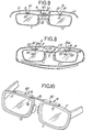
- the bridge 8 is in the form of a metal strip and is disposed with its planar surface in parallelw-to the upper sides 11, 11 of the lens frames. Alternatively, the planar surface is perpendicular to the upper side 11 of the lens frame as seen in Fig. 6.
- the bridge 8 has a fixing screw 91 screwed in one end and a plurality of screw holes 82 formed in the other end and aligned at spacing of about 3 mm. Cutout grooves 83, 83 are formed in the opposite sides of the bridge between the screw holes 82, 82. When the lens frames are adjusted to the pupil-to-pupil distance, an excess length of the bridge 8 is snapped off at a grooved portion.
- An adjusting screw 92 is screwed in a screw hole 82 at the proper position in accordance with the distance between the pupils.
- the end screws 91, 92 serve as holding means 9 for preventing the bridge 8 from slipping off, i.e. for determining the maximum effective length of the bridge 8.
- the adjusting screw 92 is removed, and the bridge 8 is moved toward or away from the holder 7 to optimally adjust the distance between the lens frames 1, 2.
- the adjusting screw 92 is then screwed in the corresponding hole 82 at the outer end of the holder 7. The excessive portion of the bridge 8 is broken off.
- the lens frames 1, 2 so arranged are moved away from each other on the bridge 8 until the end screws 91, 92, namely the holding means 9, 9, strike the outer ends of the holders 7, 7a, the distance between the lens frames 1, 2 always corresponds to the pupil-to-pupil distance. The spectacles then will not fatigue the eyes.
- the lens frames 1, 2 and the temples 4 are all arranged in the same plane as indicated in broken lines.
- the spectacles are foldable to a flat shape and convenient to carry.
- the torsion springs 15 act to raise the temples 4, 4 to an intersecting position.
- the spectacles are therefore convenient to take out.
- the bridge 8 involves reduced sliding resistance and is smoothly slidable through the holders 7, 7a when the spectacles are collapsed or stretched along the bridge 8.
- the base end of the bridge 8 may be fitted in one of the holders and secured thereto with the screw 91 or by spot welding, adhesive or the like, and the forward end of the bridge slidably fitted in the other holder 7a. After the distance between the lens frames 1, 2 has been adjusted optimally, the forward end can be fixed to the holder 7a with a clamp bolt 93.
- Figs. 7 and 8 show another embodiment comprising a main spectacle frame 10 and lens frames 1, 2 attached thereto.
- a holder 7 having a guide channel 71 extends from the lens frame 1, and a bridge 8 extends from the other lens frame 2.
- the holder 7.and the bridge 8 are slidably fitted together to render the length of the bridging portion adjustable.
- the upper sides 11 of the lens frames 1, 2 are provided with supporting pieces 16, 16 at inner midportions thereof, while the main frame 10 has bearing portions 3, 3 on the inner side thereof, each of the support pieces 16, 16 being fitted in selected one of cutout grooves 31, 31a formed in the forward edge of the corresponding bearing portion 3, whereby holding means 9 is provided for adjusting the length of the bridging portion.
- the cutout grooves 31, 31a have a width corresponding to the thickness of the support piece 16.
- two grooves 31 are formed at a pitch of 1.5 mm in each of the bearing portions 3, 3.
- the bearing portion 3 is formed at a location closer toward its forward end with a pin bore 32 along the main frame 10.
- the pin bore 32 is threaded at one end (not shown).
- a pin 33 having a threaded end is screwed into the pin bore 32 to turnably attach the support piece 16 to the bearing portion 3.
- the distance between the lens frames 1, 2 is adjustable by removing the pin 33, connecting the support piece 16 to the bearing portion of the main frame 10, from one or each of the lens frames 1, 2, and fitting the support piece 16 to the other adjacent groove.
- two grooves 31, 31a are formed at a pitch of 1.5 mm in each of the bearing portions 3, 3, so that according to the user, the support pieces may be both fitted in the outer grooves 31 of the bearing portions 3, 3, or one of the support piece may be fitted in the outer groove 31 of one portion and the other support piece in the inner groove 31a of the other portion, or both the support pieces may be fitted in the inner grooves 31a.
- the distance between the two lens frames 1, 2 is adjustable in three ways with an increment or decrement of 1.5 mm in accordance with the distance between the pupils.
- the frame-to-frame distance is similarly adjustable when the bearing portions 3 are formed on the lens frames 1, 2, with the support pieces 16 provided on the main frame 10.
- Fig. 9 shows another embodiment of the holding means 9 for determining the effective length of the bridge 8.
- a holder 7 having a slit 72 extends from one lens frame 1, while a bridge 8 extending from the other lens frame 2 has a threaded hole 81.
- a clamp bolt 93 slidably extending through the slit 72 is screwed in the threaded hole 81 to give a desired length to the bridging portion.
- the spectacle main frame 10 has bearing portions 3 each formed with a cutout portion inwhich a support piece 16 on each of the lens frames 1, 2 is shiftably fittable.
- the support piece 16 is pivotably supported by a pin 33 in the cutout portion
- the pins 33 each have a torsion spring 15 wound thereon for biasing the lens frames 1, 2 toward an unfolding direction.
- the spectacles of this invention are useful as those in which the center-to-center distance between the lenses is easily adjustable to the pupol-to-pupil distance
Landscapes
- Physics & Mathematics (AREA)
- Health & Medical Sciences (AREA)
- General Physics & Mathematics (AREA)
- Ophthalmology & Optometry (AREA)
- Optics & Photonics (AREA)
- Eyeglasses (AREA)
Abstract
Priority Applications (2)
| Application Number | Priority Date | Filing Date | Title |
|---|---|---|---|
| AT81900263T ATE19440T1 (de) | 1980-08-01 | 1981-01-14 | Zusammenklappbare brille. |
| HK29/89A HK2989A (en) | 1980-08-01 | 1989-01-12 | Collapsible glasses frame |
Applications Claiming Priority (4)
| Application Number | Priority Date | Filing Date | Title |
|---|---|---|---|
| JP10991180U JPS5732924U (fr) | 1980-08-01 | 1980-08-01 | |
| JP1980109910U JPS6027373Y2 (ja) | 1980-08-01 | 1980-08-01 | 縮小できる眼鏡 |
| JP109910/80U | 1980-08-01 | ||
| PCT/JP1981/000009 WO1982000530A1 (fr) | 1980-08-01 | 1981-01-14 | Monture de lunettes repliable |
Publications (3)
| Publication Number | Publication Date |
|---|---|
| EP0056822A1 true EP0056822A1 (fr) | 1982-08-04 |
| EP0056822A4 EP0056822A4 (fr) | 1982-09-16 |
| EP0056822B1 EP0056822B1 (fr) | 1986-04-23 |
Family
ID=26449611
Family Applications (1)
| Application Number | Title | Priority Date | Filing Date |
|---|---|---|---|
| EP81900263A Expired EP0056822B1 (fr) | 1980-08-01 | 1981-01-14 | Monture de lunettes repliable |
Country Status (3)
| Country | Link |
|---|---|
| EP (1) | EP0056822B1 (fr) |
| AU (1) | AU529772B2 (fr) |
| WO (1) | WO1982000530A1 (fr) |
Cited By (8)
| Publication number | Priority date | Publication date | Assignee | Title |
|---|---|---|---|---|
| GB2166887A (en) * | 1984-11-08 | 1986-05-14 | Winter Optik | Spectacles with variable lens spacing and telescopic temples |
| FR2632736A1 (fr) * | 1988-06-14 | 1989-12-15 | Girard Edouard | Additif ou face complementaire a protection solaire pour lunettes optiques |
| EP0515826A1 (fr) * | 1991-05-28 | 1992-12-02 | Kanda Optical Co., Ltd. | Monture de lunettes pliable |
| WO1995010064A1 (fr) * | 1993-10-07 | 1995-04-13 | Giorgio Nannini S.R.L. | Lunettes repliables |
| EP0782030A1 (fr) * | 1994-12-06 | 1997-07-02 | Kanda Optical Co., Ltd. | Lunettes pliables en étui |
| RU2240585C2 (ru) * | 2003-01-27 | 2004-11-20 | Шишков Владимир Семенович | Устройство для коррекции зрения |
| WO2014088953A1 (fr) | 2012-12-05 | 2014-06-12 | Visoptical, Llc | Lunettes extensibles et procédé d'utilisation |
| WO2020210884A1 (fr) * | 2019-04-18 | 2020-10-22 | Luis Alvim Malta Andre | Monture pour lunettes à ajustements multiples |
Family Cites Families (7)
| Publication number | Priority date | Publication date | Assignee | Title |
|---|---|---|---|---|
| GB191325442A (en) * | 1913-11-07 | 1914-08-13 | Francis Howard Wheway | Improvements relating to Eyeglasses. |
| DE470102C (de) * | 1925-05-07 | 1929-01-08 | Giuseppe Ratti | Verstellbarer Nasensteg fuer Schutzbrillen |
| US2047646A (en) * | 1934-01-30 | 1936-07-14 | Bay State Optical Co | Eyeglass construction |
| GB480479A (en) * | 1936-01-30 | 1938-02-23 | Marius Moderne | Improvements in or relating to spectacle frames |
| US2856813A (en) * | 1955-05-03 | 1958-10-21 | Kudelko Antonia | Spectacle frame with adjustable bridge and temples |
| JPS3818556Y1 (fr) * | 1961-02-18 | 1963-09-03 | ||
| JPS4721644U (fr) * | 1971-02-24 | 1972-11-10 |
-
1981
- 1981-01-14 AU AU67067/81A patent/AU529772B2/en not_active Expired
- 1981-01-14 EP EP81900263A patent/EP0056822B1/fr not_active Expired
- 1981-01-14 WO PCT/JP1981/000009 patent/WO1982000530A1/fr not_active Ceased
Cited By (14)
| Publication number | Priority date | Publication date | Assignee | Title |
|---|---|---|---|---|
| GB2166887A (en) * | 1984-11-08 | 1986-05-14 | Winter Optik | Spectacles with variable lens spacing and telescopic temples |
| FR2632736A1 (fr) * | 1988-06-14 | 1989-12-15 | Girard Edouard | Additif ou face complementaire a protection solaire pour lunettes optiques |
| EP0515826A1 (fr) * | 1991-05-28 | 1992-12-02 | Kanda Optical Co., Ltd. | Monture de lunettes pliable |
| US5231429A (en) * | 1991-05-28 | 1993-07-27 | Kanda Optical Co., Ltd. | Foldable spectacle frame |
| WO1995010064A1 (fr) * | 1993-10-07 | 1995-04-13 | Giorgio Nannini S.R.L. | Lunettes repliables |
| AU676769B2 (en) * | 1993-10-07 | 1997-03-20 | Giorgio Nannini S.R.L. | Collapsible spectacles |
| US5638146A (en) * | 1993-10-07 | 1997-06-10 | Giorgio Nannini S.R.L. | Collapsible spectacles |
| EP0782030A1 (fr) * | 1994-12-06 | 1997-07-02 | Kanda Optical Co., Ltd. | Lunettes pliables en étui |
| RU2240585C2 (ru) * | 2003-01-27 | 2004-11-20 | Шишков Владимир Семенович | Устройство для коррекции зрения |
| WO2014088953A1 (fr) | 2012-12-05 | 2014-06-12 | Visoptical, Llc | Lunettes extensibles et procédé d'utilisation |
| EP2929392A4 (fr) * | 2012-12-05 | 2016-12-14 | Visoptical Llc | Lunettes extensibles et procédé d'utilisation |
| US9726901B2 (en) | 2012-12-05 | 2017-08-08 | Visoptical, Llc | Extendable eyeglasses and method of use |
| EP3407118A1 (fr) * | 2012-12-05 | 2018-11-28 | Visoptical, LLC | Lunettes extensibles et procédé d'utilisation |
| WO2020210884A1 (fr) * | 2019-04-18 | 2020-10-22 | Luis Alvim Malta Andre | Monture pour lunettes à ajustements multiples |
Also Published As
| Publication number | Publication date |
|---|---|
| AU529772B2 (en) | 1983-06-16 |
| EP0056822A4 (fr) | 1982-09-16 |
| AU6706781A (en) | 1982-03-02 |
| WO1982000530A1 (fr) | 1982-02-18 |
| EP0056822B1 (fr) | 1986-04-23 |
Similar Documents
| Publication | Publication Date | Title |
|---|---|---|
| US4820035A (en) | Collapsible spectacles | |
| US6520636B2 (en) | Nosepiece assembly for an adjustable eyeglass frame | |
| US4017165A (en) | Eyeglass frames | |
| US5372345A (en) | Eyeglass holder | |
| US5422686A (en) | Detachable eyeglass assembly for visored headgear | |
| US5028126A (en) | Foldable spectacle frame | |
| KR20090097847A (ko) | 기구학적 만능 힌지 | |
| GB1530691A (en) | Spectacle structure | |
| US5793463A (en) | Universal attachment with moveable sideshields for eyeglasses | |
| WO2009090733A1 (fr) | Monture de lunettes sans plaquette et son procédé de support de verres | |
| JP2008286884A (ja) | 多焦点用眼鏡枠 | |
| EP0056822A1 (fr) | Monture de lunettes repliable | |
| US2571704A (en) | Ophthalmic mounting | |
| US4762406A (en) | Modular eyeglasses | |
| KR100964077B1 (ko) | 안경테용 코걸이 조립체 | |
| US1905675A (en) | Ophthalmic mounting | |
| MXPA01007456A (es) | Anteojos para maquillaje. | |
| US5640218A (en) | Foldable spectacles with temple members having deformable earpieces for fitting into compact case | |
| US5576776A (en) | Folding eyeglasses | |
| US4666266A (en) | Eyeglasses having lens storage means | |
| JP2000155292A (ja) | 多焦点用眼鏡枠及びパッド | |
| US6877855B2 (en) | Spectacles with peripheral lens support | |
| US6325506B1 (en) | Interchangeable eyeglass lens system | |
| EP0153349B1 (fr) | Monture de lunette reglable | |
| HK2989A (en) | Collapsible glasses frame |
Legal Events
| Date | Code | Title | Description |
|---|---|---|---|
| PUAI | Public reference made under article 153(3) epc to a published international application that has entered the european phase |
Free format text: ORIGINAL CODE: 0009012 |
|
| AK | Designated contracting states |
Kind code of ref document: A1 Designated state(s): AT CH DE FR GB SE |
|
| 17P | Request for examination filed |
Effective date: 19820624 |
|
| RAP1 | Party data changed (applicant data changed or rights of an application transferred) |
Owner name: KANDA OPTICAL CO., LTD. |
|
| GRAA | (expected) grant |
Free format text: ORIGINAL CODE: 0009210 |
|
| AK | Designated contracting states |
Kind code of ref document: B1 Designated state(s): AT CH DE FR GB LI SE |
|
| REF | Corresponds to: |
Ref document number: 19440 Country of ref document: AT Date of ref document: 19860515 Kind code of ref document: T |
|
| ET | Fr: translation filed | ||
| REF | Corresponds to: |
Ref document number: 3174442 Country of ref document: DE Date of ref document: 19860528 |
|
| PLBE | No opposition filed within time limit |
Free format text: ORIGINAL CODE: 0009261 |
|
| STAA | Information on the status of an ep patent application or granted ep patent |
Free format text: STATUS: NO OPPOSITION FILED WITHIN TIME LIMIT |
|
| 26N | No opposition filed | ||
| PGFP | Annual fee paid to national office [announced via postgrant information from national office to epo] |
Ref country code: AT Payment date: 19911218 Year of fee payment: 12 |
|
| PG25 | Lapsed in a contracting state [announced via postgrant information from national office to epo] |
Ref country code: AT Effective date: 19930114 |
|
| EAL | Se: european patent in force in sweden |
Ref document number: 81900263.5 |
|
| PGFP | Annual fee paid to national office [announced via postgrant information from national office to epo] |
Ref country code: CH Payment date: 19991224 Year of fee payment: 20 |
|
| PGFP | Annual fee paid to national office [announced via postgrant information from national office to epo] |
Ref country code: FR Payment date: 20000105 Year of fee payment: 20 Ref country code: GB Payment date: 20000105 Year of fee payment: 20 |
|
| PGFP | Annual fee paid to national office [announced via postgrant information from national office to epo] |
Ref country code: SE Payment date: 20000118 Year of fee payment: 20 |
|
| PGFP | Annual fee paid to national office [announced via postgrant information from national office to epo] |
Ref country code: DE Payment date: 20000128 Year of fee payment: 20 |
|
| PG25 | Lapsed in a contracting state [announced via postgrant information from national office to epo] |
Ref country code: LI Free format text: LAPSE BECAUSE OF EXPIRATION OF PROTECTION Effective date: 20010113 Ref country code: GB Free format text: LAPSE BECAUSE OF EXPIRATION OF PROTECTION Effective date: 20010113 Ref country code: CH Free format text: LAPSE BECAUSE OF EXPIRATION OF PROTECTION Effective date: 20010113 |
|
| PG25 | Lapsed in a contracting state [announced via postgrant information from national office to epo] |
Ref country code: SE Free format text: THE PATENT HAS BEEN ANNULLED BY A DECISION OF A NATIONAL AUTHORITY Effective date: 20010130 |
|
| REG | Reference to a national code |
Ref country code: CH Ref legal event code: PL |
|
| REG | Reference to a national code |
Ref country code: GB Ref legal event code: PE20 Effective date: 20010113 |
|
| EUG | Se: european patent has lapsed |
Ref document number: 81900263.5 |