EP0056834B1 - Verfahren zur Herstellung einer Rohrheizkörpereinbaueinheit - Google Patents
Verfahren zur Herstellung einer Rohrheizkörpereinbaueinheit Download PDFInfo
- Publication number
- EP0056834B1 EP0056834B1 EP81102911A EP81102911A EP0056834B1 EP 0056834 B1 EP0056834 B1 EP 0056834B1 EP 81102911 A EP81102911 A EP 81102911A EP 81102911 A EP81102911 A EP 81102911A EP 0056834 B1 EP0056834 B1 EP 0056834B1
- Authority
- EP
- European Patent Office
- Prior art keywords
- tubular
- fixing plate
- tubular heater
- holes
- annular space
- Prior art date
- Legal status (The legal status is an assumption and is not a legal conclusion. Google has not performed a legal analysis and makes no representation as to the accuracy of the status listed.)
- Expired
Links
- 238000004519 manufacturing process Methods 0.000 title claims abstract description 8
- 238000010438 heat treatment Methods 0.000 title description 17
- 238000003466 welding Methods 0.000 claims abstract description 20
- 238000000034 method Methods 0.000 claims abstract description 16
- 239000000853 adhesive Substances 0.000 claims abstract description 11
- 230000001070 adhesive effect Effects 0.000 claims abstract description 11
- 239000003990 capacitor Substances 0.000 claims description 4
- 238000009434 installation Methods 0.000 description 9
- 238000007789 sealing Methods 0.000 description 9
- CPLXHLVBOLITMK-UHFFFAOYSA-N magnesium oxide Inorganic materials [Mg]=O CPLXHLVBOLITMK-UHFFFAOYSA-N 0.000 description 6
- 239000000395 magnesium oxide Substances 0.000 description 6
- AXZKOIWUVFPNLO-UHFFFAOYSA-N magnesium;oxygen(2-) Chemical compound [O-2].[Mg+2] AXZKOIWUVFPNLO-UHFFFAOYSA-N 0.000 description 6
- 239000011810 insulating material Substances 0.000 description 4
- 238000005476 soldering Methods 0.000 description 4
- 239000007788 liquid Substances 0.000 description 3
- 239000000463 material Substances 0.000 description 3
- PXHVJJICTQNCMI-UHFFFAOYSA-N nickel Substances [Ni] PXHVJJICTQNCMI-UHFFFAOYSA-N 0.000 description 3
- 229910000679 solder Inorganic materials 0.000 description 3
- 229910000831 Steel Inorganic materials 0.000 description 2
- 239000011324 bead Substances 0.000 description 2
- 238000010276 construction Methods 0.000 description 2
- 238000005260 corrosion Methods 0.000 description 2
- 230000007797 corrosion Effects 0.000 description 2
- 229910052759 nickel Inorganic materials 0.000 description 2
- 239000003566 sealing material Substances 0.000 description 2
- 239000010959 steel Substances 0.000 description 2
- RYGMFSIKBFXOCR-UHFFFAOYSA-N Copper Chemical compound [Cu] RYGMFSIKBFXOCR-UHFFFAOYSA-N 0.000 description 1
- BQCADISMDOOEFD-UHFFFAOYSA-N Silver Chemical compound [Ag] BQCADISMDOOEFD-UHFFFAOYSA-N 0.000 description 1
- 239000011248 coating agent Substances 0.000 description 1
- 238000000576 coating method Methods 0.000 description 1
- 150000001875 compounds Chemical class 0.000 description 1
- 229910052802 copper Inorganic materials 0.000 description 1
- 239000010949 copper Substances 0.000 description 1
- 238000001723 curing Methods 0.000 description 1
- 239000013013 elastic material Substances 0.000 description 1
- 239000003822 epoxy resin Substances 0.000 description 1
- 238000013007 heat curing Methods 0.000 description 1
- 230000014759 maintenance of location Effects 0.000 description 1
- 229910000480 nickel oxide Inorganic materials 0.000 description 1
- GNRSAWUEBMWBQH-UHFFFAOYSA-N oxonickel Chemical compound [Ni]=O GNRSAWUEBMWBQH-UHFFFAOYSA-N 0.000 description 1
- 229920000647 polyepoxide Polymers 0.000 description 1
- 229910052709 silver Inorganic materials 0.000 description 1
- 239000004332 silver Substances 0.000 description 1
- 229910001220 stainless steel Inorganic materials 0.000 description 1
- 239000010935 stainless steel Substances 0.000 description 1
Images
Classifications
-
- F—MECHANICAL ENGINEERING; LIGHTING; HEATING; WEAPONS; BLASTING
- F28—HEAT EXCHANGE IN GENERAL
- F28F—DETAILS OF HEAT-EXCHANGE AND HEAT-TRANSFER APPARATUS, OF GENERAL APPLICATION
- F28F9/00—Casings; Header boxes; Auxiliary supports for elements; Auxiliary members within casings
- F28F9/02—Header boxes; End plates
- F28F9/04—Arrangements for sealing elements into header boxes or end plates
- F28F9/16—Arrangements for sealing elements into header boxes or end plates by permanent joints, e.g. by rolling
- F28F9/162—Arrangements for sealing elements into header boxes or end plates by permanent joints, e.g. by rolling by using bonding or sealing substances, e.g. adhesives
-
- H—ELECTRICITY
- H05—ELECTRIC TECHNIQUES NOT OTHERWISE PROVIDED FOR
- H05B—ELECTRIC HEATING; ELECTRIC LIGHT SOURCES NOT OTHERWISE PROVIDED FOR; CIRCUIT ARRANGEMENTS FOR ELECTRIC LIGHT SOURCES, IN GENERAL
- H05B3/00—Ohmic-resistance heating
- H05B3/02—Details
- H05B3/06—Heater elements structurally combined with coupling elements or holders
-
- H—ELECTRICITY
- H05—ELECTRIC TECHNIQUES NOT OTHERWISE PROVIDED FOR
- H05B—ELECTRIC HEATING; ELECTRIC LIGHT SOURCES NOT OTHERWISE PROVIDED FOR; CIRCUIT ARRANGEMENTS FOR ELECTRIC LIGHT SOURCES, IN GENERAL
- H05B3/00—Ohmic-resistance heating
- H05B3/40—Heating elements having the shape of rods or tubes
- H05B3/42—Heating elements having the shape of rods or tubes non-flexible
- H05B3/48—Heating elements having the shape of rods or tubes non-flexible heating conductor embedded in insulating material
Definitions
- the invention relates to a method for producing a tubular heater installation unit, in which the tubular heater ends are sealingly connected with a fastening plate provided with corresponding holes so that the connecting ends of the tubular heater are on the outside of the plate and the tubular heater itself is on the inside of the plate, and a Tubular radiator installation unit manufactured according to the method.
- Tubular heaters generally consist of a jacket tube, e.g. made of chrome-nickel steel, one in an insulating compound, generally magnesium oxide, embedded heating coil and from the connecting parts.
- the latter are generally connection bolts to which one end of the heating coil is welded.
- the connecting bolts are passed through an insulating bead or another insulating body which sits in the end section of the casing tube.
- the jacket tube is now closed at its ends by means of an adhesive which, after curing, on the one hand protects the insulating material, that is to say the magnesium oxide, against ingress of moisture and, on the other hand, improves the mechanical retention of the connecting bolt in the associated end of the jacket tube.
- Tubular heating elements in the form of a hairpin or a W-shape are inserted through holes in a fastening plate in the case of a more extensive construction, in which case the ends of the casing tube generally protrude 8 to 12 mm beyond the surface of the fastening plate facing the connecting bolts.
- the feedthrough through the mounting plate must be absolutely watertight.
- the fixing and sealing of the tubular heater ends in the holes of the mounting plate is generally done by soldering. This work is relatively expensive and cumbersome considering the fact that tubular radiator installation units are mass-produced items with extremely low prices. Despite the greatest care, a relatively large committee cannot be avoided.
- a sealing body made of elastic material and a counter flange plate which can move on the tubular heating element leg can be applied before or after attaching the fastening plate.
- the mounting plate or the counter flange plate carries a screw bolt.
- the sealing body is pressed together by tightening a corresponding nut and is generally pressed against the edges of a container wall opening.
- the fastening plate covering the container wall opening is screwed onto the container with the interposition of a sealing ring.
- the tubular radiator installation units produced in this way can have different designs.
- the invention is applicable to all constructions in which the tubular heater ends are passed through holes in a fastening plate and are fixed in a sealing manner therein.
- the soldering must be done from the outside, i.e. the ring-shaped solder joint is located on the lower side of the flange plate which later turns towards the inside of the container and extends in a ring around the outside of the tubular heating element jacket.
- insulating material e.g. Magnesium oxide
- a plate e.g. become known for the production of heat exchangers. Since the pipes are unfilled, i.e. hollow, in contrast to tubular heaters, in which the pipes are filled with the heating coil and insulating material and in which the connecting bolts protrude beyond the pipe end, the conical end of a welding electrode can penetrate into the open pipe end. By means of a counterelectrode pressed against the underside of the plate, the tube end projecting beyond the plate is welded off. The flowing material connects to the plate, so that a correspondingly durable and tight weld connection can be made.
- capacitor welding is known, for example, from DE-A-2 218 143.
- a capacitor bank is charged with direct current.
- the stored energy is for welding over the workpieces to be welded together.
- the invention is based on the object of simplifying the manufacture of tubular heater installation units by improving the sealing of the tubular heater ends in the holes in the fastening plate, with a reject being almost completely avoided.
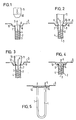
- a hairpin-shaped tubular heater 1 consists of a casing tube 2 and a filling of insulating material, e.g. Made of magnesium oxide 4.
- the heating coil 3 is welded or soldered to a connecting bolt 5.
- the magnesium oxide filling 4 ends at a distance from the end edge 6 of the casing tube 2, so that an annular space 7 remains for receiving the end seal.
- the annular space 7 is not closed in the new method. Rather, as shown in FIG. 1, the tubular heater ends are inserted through associated holes 8 in a fastening plate 9 such that the end edge 6 protrudes somewhat beyond the outside of the fastening plate 9.
- the fastening plate 9 preferably has a depression 10 in the region of the holes 8.
- a welding electrode 11 of a capacitor welding device (not shown in detail) has a conical end 12, the smallest diameter at the cone end being smaller than the inside diameter of the jacket tube 2 and the diameter of the cone widening beyond the dimension of the outside diameter of the jacket tube 2.
- the welding electrode 11 is hollow, as indicated at 13 in FIG. 2, so that it can receive the connecting bolt 5.
- the welding electrode is now inserted into the open end of the tubular heating element as shown in FIG. 2, the end edge 6 being flanged out, as shown in FIG. 3.
- the end edge 6 is welded to the edges of the hole 8.
- a durable fixation is essential. Practice has shown, however, that both the fixation and the sealing are entirely satisfactory with the proposed method.
- the annular space 7 is filled with an adhesive, as shown in FIG.
- the entire recess 10 is filled with the adhesive. This creates the possibility of extensive automation. So while in known methods it was necessary to ensure that as far as possible no adhesive gets onto the outer wall of the tubular heater, since the adhesive residues adhering made it difficult to insert into the holes in the mounting plate, the application of the adhesive is much less problematic in the described method.
- the adhesive therefore fulfills two different functions, namely that on the one hand the end of the tubular heating element is protected against the ingress of moisture, and on the other hand the passage of the casing tubes 2 of the tubular heating element 1 is sealed by the holes 8 of the fastening plate 9.
- the magnesium oxide layer 4 can be protected against welding by means of an intermediate layer. It is only essential that an intermediate space remains, into which the welding electrode 11 can penetrate. Furthermore, insulating beads or similar connection elements can be used in the usual way.
- the welding process can be varied accordingly.
- the casing tube 2 of the tubular heater can have a larger diameter than the hole 8, the end edges 6 then being drawn in to the hole diameter.
- the end edge 6 can be butt-welded to the underside of the mounting plate 9.
- the hole 8 can be expressed conically downwards while the end edge 6 of the tubular casing 2 is flared. The welding then takes place over the conical inclined surfaces.
- the tubular heater ends can be welded individually in the assigned holes. However, a plurality of welding electrodes 11 can also be used, which simultaneously weld the tubular heater ends in the assigned holes 8.
Landscapes
- Engineering & Computer Science (AREA)
- Physics & Mathematics (AREA)
- Thermal Sciences (AREA)
- Mechanical Engineering (AREA)
- General Engineering & Computer Science (AREA)
- Resistance Heating (AREA)
- Pipe Accessories (AREA)
Description
- Die Erfindung betrifft ein Verfahren zur Herstellung einer Rohrheizkörpereinbaueinheit, bei dem die Rohrheizkörperenden mit einer mit entsprechenden Löckern versehenen Befestigungsplatte abdichtend so verbunden werden, daß die Anschlußenden des Rohrheizkörpers auf der Außenseite der Platte und der Rohrheizkörper selbst auf der Innenseite der Platte sich befinden, sowie eine nach dem Verfahren hergestellte Rohrheizkörpereinbaueinheit.
- Rohrheizkörper bestehen im allgemeinen aus einem Mantelrohr, z.B. aus Chrom-Nickel-Stahl, einer in einer Isoliermasse, im allgemeinen Magnesiumoxid, eingebetteten Heizwendel und aus den Anschlußteilen. Bei Letzteren handelt es sich im allgemeinen um Anschlußbolzen, an welche je ein Ende der Heizwendel angeschweißt ist. Die Anschlußbolzen werden durch eine Isolierperle oder einen anderen Isolierkörper hindurchgeführt, welcher in dem Endabschnitt des Mantelrohres sitzt. Das Mantelrohr wird nun an seinen Enden mittels eines Klebers verschlossen, der nach dem Aushärten einerseits das Isoliermaterial, also das Magnesiumoxid, gegen Eindrigen von Feuchtigkeit schützt und der andererseits die mechanische Halterung des Anschlußbolzens in dem zugeordneten Ende des Mantelrohres verbessert.
- Derartig fertiggestellte und z.B. haarnadelförmig oder W-förmig gebogene Rohrheizkörper werden bei überlichen Konstruktion durch Löcher in einer Befestigungsplatte hindurchgesteckt, wobei dann die Enden des Mantelrohres im allgemeinem 8 bis 12 mm über die den Anschlußbolzen zugewendete Fläche der Befestigungsplatte hinausragen. Für alle Zwecke, in denen Rohrheizkörper in flüssigen Medien betrieben werden, muß die Durchführung durch die Befestigungsplatte absolut wasserdicht sein. Die Fixierung und Abdichtung der Rohrheizkörperenden in den Löchern der Befestigungsplatte erfolgt im allgemeinen durch Lötung. Diese Arbeit ist unter Berücksichtigung des Umstandes, daß Rohrheizkörpereinbaueinheiten äußerst niedrig kalkulierte Massenartikel sind, verhältnismäßig kostspielig und umständlich. Trotz größter Sorgfalt läßt sich ein relativ großer Ausschuß nicht vermeiden.
- Zur Vervollständigung der Rohrheizkörpereinbaueinheit kann vor oder nach dem Anbringen der Befestigungsplatte ein Dichtkörper aus elastischem Material une eine auf den Rohrheizkörperschenkel bewegliche Gegenflanschplatte aufgebracht werden. Die Befestigungsplatte oder die Gegenflanschplatte trägt einen Schraubenbolzen. Durch Anziehen einer entsprechenden Mutter wird der Dichtkörper zusammengepreßt und im allgemeinen an die Ränder einer Behälterwandöffnung angepreßt. Im allgemeinen wird jedoch die Behälterwandöffnung überdeckende Befestigungsplatte unter Zwischenlage eines Dichtringes an den Behälter angeschraubt. Die so hergestellten Rohrheizkörpereinbaueinheiten können verschiedene Konstruktion haben. Die Erfindung ist anwendbar auf sämtliche Konstruktionen, bei denen die Rohrheizkörperenden durch Löcher einer Befestigungsplatte hindurchgeführt und in dieser abdichtend fixiert sind.
- Aus der US-A-2 860 227 ist ein Verfahren zur Herstellung von Rohrheizkörperanordnungen für die Erhitzung von Flüssigkeiten bekannt geworden, bei dem die Enden des Rohrheizkörpermantelrohres in Löcher einer dünnen Flanschplatte eingesteckt und dann z.B. durch Silberlöten in derselben abdichtend befestigt werden (Spalte 2, Zeilen 15 und 16). Anschließend wird die muldenförmige Vertiefung der Flanschplatte mit einem elektrisch isolierenden Abdichtmaterial ausgefüllt. Als Dichtmaterial wird vorzugsweise ein wärmehärtendes Epoxy-Kunstharz verwendet, welches man flüssig eingießt und dann aushärten läßt.
- Da die Rohrheizkörperenden bis über das zugeordnete Loch in der Flanschplatte hinaus mit Isoliermaterial, z.B. Magnesiumoxid, gefüllt sind, muß das Verlöten von außen her erfolgen, d.h. die ringförmige Lötstell befindet sich an der später dem Behälterinneren zugewendeten unteren Seite der Flanschplatte und erstreckt sich ringförmig um die Außenseite des Rohrheizkörpermantels.
- Die Herstellung entsprechend dichter Silberlöstellen ist materialmäßig teuer und zeitaufwendig. Da die Rohrheizkörpermantelrohre nicht wie in früherer Zeit aus Kupfer, sondern wegen der Korrosionsbeständigkeit überwiegend aus Edelstählen, gegebenenfalls mit Nickel-oder Nickel-Oxid-Beschichtung bestehen, werden die Lötarbeiten problematisch. Da die Flanschplatten aus Kostengründen oftmals nicht aus hochwertigen Stählen bestehen, ergeben sich die Potentialunterschiede zwischen den Materialien-Manteirohr-Sitberiot-Fianschpiatte erhebliche Korrosionsprobleme.
- Es sind weiterhin aus der FR-A-2 264 620 und der US-A-2 614198 Verfahren zum Befestigen von Rohren in den Löchern eine Platte, z.B. zwecks Herstellung von Wärmeaustauschern bekannt geworden. Da die Rohre ungefüllt, also hohl sind, kann man im Gegensatz zu Rohrheizkörpern, bei denen die Rohre mit der Heizwendel und Isoliermaterial gefüllt sind und bei denen der Anschlußbolzen über das Rohrende hinaus vorsteht, mit dem konischen Ende einer Schweißelektrode in das offene Rohrende eindringen. Durch eine an die Unterseite der Platte angedrückte Gegenelektrode wird so erreicht, daß das über die Platte hinausstehende Rohrende abgeschweißt wird. Das abfließende Material verbindet sich mit der Platte, so daß eine entsprechend haltbare und dichte Schweißverbindung hergestellt werden kann.
- Weiterhin ist z.B. aus der DE-A-2 218 143 die Technik des Kondensatorschweißens bekannt. Hierbei wird eine Kondensatorbatterie mit Gleichstrom geladen. Die gespeicherte Energie wird zum Schweißen über die miteinander zu verschweißenden Werkstücke entladen.
- Der Erfindung liegt nun die Aufgabe zugrunde, die Herstellung von Rohrheizkörpereinbaueinheiten unter Verbesserung der Abdichtung der Rohrheizkörperenden in den Löchern der Befestigungsplatte zu vereinfachen, wobei ein Ausschuß fast vollständig vermieden werden kann.
- Dem Problem der Reduzierung des Ausschusses kommt dabei insofern besondere Bedeutung zu, da eine Nachbesserung bisheriger fehlerhafter Lötstellen in der fertigen Rohrheizkörpereinbaueinheit im allgemeinen nicht möglich ist, so daß die gesamte Rohrheizkörpereinbaueinzeit verworfen werden muß, d.h. der Gesamtwert des hergestellten Produktes einschließlich dem Rohrheizkörper usw. verlorengeht. Die Wirtschaftlichkeitsberechnung ergibt dabei, daß jedes Prozent Ausschuß sich in mehr als einer Verdoppelung der Kosten für das Fixieren und Abdichten der Rohrheizkörperenden in den Löchern der Befestigungsplatte auswirkt. Die Lösung der genannten Aufgabe ergibt sich aus den kennzeichnenden Merkmalen des Patentanspruche 1.
- Die beiliegende Zeichnung dient der weiteren Erläuterung des Verfahrens gemäß der Erfindung. Es zeigen:
- Fig. 1 bis Fig. 4 einen Schnitt der Durchführung eines Rohrheizkörperendes durch die Befestigungsplatte je entsprechend den Verfahrensstufen;
- Fig. 5 in etwas verkleinertem Maßstab eine Seitenschnittansicht der fertiggestellten Rohrheizkörpereinbaueinheit.
- Ein haarnadelförmig gebogener Rohrheizkörper 1 besteht aus einem Mantelrohr 2 und einer Füllung aus Isoliermaterial, z.B. aus Magnesium-oxid 4. Die Heizwendel 3 ist an einen Anschlußbolzen 5 angeschweißt oder angelötet. Die Magnesiumoxidfüllung 4 endet im Abstand von dem Stirnrand 6 des Mantelrohres 2, so daß ein Ringraum 7 zur Aufnahme der Endenabdichtung bleibt.
- Im Unterschied zu bekannten Verfahren wird bei dem neuen Verfahren der Ringraum 7 nicht verschlossen. Die Rohrheizkörperenden werden vielmehr, wie dies Figur 1 zeigt, durch zugeordnete Löcher 8 in einer Befestigungsplatte 9 hindurchgesteckt, daß der Stirnrand 6 etwas über die Außenseite der Befestigungsplatte 9 vorsteht. Vorzugsweise besitzt die Befestigungsplatte 9 im Bereich der Löcher 8 eine Vertiefung 10.
- Eine Schweißelektrode 11 einer nicht näher dargestellten Kondensatorschweißeinrichtung besitzt ein konisches Ende 12, wobei der kleinste Durchmesser am Konusende kleiner ist als der Innendurchmesser des Mantelrohrs 2 und sich der Durchmesser des Konus bis über das Maß des Außendurchmesser des Mantelrohres 2 erweitert.
- Die Schweißelektrode 11 ist, wie bei 13 in Fig. 2 angedeutet, hohl, so daß sie den Anschlußbolzen 5 aufnehmen kann. Die Schweißelektrode wird nun entsprechend der Darstellung in Fig. 2 in das offene Ende des Rohrheizkörpers eingeführt, wobei der Stirnrand 6, wie in Fig. 3 dargestellt, ausgebördelt wird. Gleichzeitig wird der Stirnrand 6 mit den Rändern des Loches 8 verschweißt. Besonders hervorzuheben ist, daß es dabei nicht auf eine absolute Abdichtung des Rohrheizkörpers in dem Loch ankommt. Wesentlich ist eine haltbare Fixierung. Die Praxis zeigte jedoch, daß sowohl die Fixierung als auch die Abdichtung bei dem vorgeschlagenen Verfahren durchaus zufriedenstellend ist.
- Nach Zurückziehen der Schweißelektrode wird, wie in Fig. 4 dargestellt, der Ringraum 7 mit einem Kleber ausgefüllt, wobei sich der sich bildende Klebstoffpfropfen 14 zumindest über den ausgebördelten Stirnrand 6 des Rohrheizkörpermantels 2 erstreckt. Bevorzugt wird jedoch, wenn wie in Fig. 5 dargestellt-die gesamte Vertiefung 10 mit dem Klebstoff ausgefüllt wird. Dadurch ergibt sich die Möglichkeit einer weitgehenden Automatisierung. Während also bei bekannten Verfahren sorgfältig darauf geachtet werden mußte, daß moglichst kein Kleber an die Außenwand des Rohrheizkörpers gelangt, da durch die anhaftenden Klebstoffreste das Einstecken in die Löcher der Befestigungsplatte erschwert wurde, gestaltet sich bei dem beschriebenen Verfahren der Auftrag des Klebers wesentlich unproblematischer.
- Der Kleber erfüllt also zwei verschiedene Funktionen, und zwar wird einerseits das Ende des Rohrheizkörpers gegen Eindringen von Feuchtigkeit geschützt, anderseits wird die Durchführung der Mantelrohre 2 des Rohrheizkörpers 1 durch die Löcher 8 der Befestigungsplatte 9 abgedichtet.
- Das angegebene neue Schweißverfahren hat sich besonders bewährt. Selbstverständlich kann die Magnesiumoxidschicht 4 mittels einer Zwischenschicht vor dem Anschweißen geschützt werden. Wesentlich ist nur, daß ein Zwischenraum verbleibt, in den die Schweißelektrode 11 eindringen kann. Weiterhin können in üblicher Weise Isolierperlen oder ähnliche Anschlußelemente Verwendung finden.
- Das Schweißverfahren kann entsprechend variiert werden. Das Mantelrohr 2 des Rohrheizkörpers kann einen größeren Durchmesser als die Loch 8 besitzen, wobei dann die Stirnränder 6 auf den Lochdurchmesser eingezogen werden. Weiterhin kann bei dieser Durchmesserwahl der Stirnrand 6 an der Unterseite der Befestigungsplatte 9 stumpf angeschweißt werden. Weiterhin kann das Loch 8 nach unten konisch ausgedrückt sein während der Stirnrand 6 des Mantelrohres 2 konisch aufgeweitet ist. Die Veschweißung erfolgt dann über die konischen Schrägflächen.
- Die Veschweißung der Rohrheizkörperenden in den zugeordneten Löchern kann einzeln erfolgen. Es können jedoch auch mehrere Schweißelektroden 11 verwendet werden, die gleichzeitig die Rohrheizkörperenden in den zugeordneten Löchern 8 verschweißen.
Claims (2)
Priority Applications (1)
| Application Number | Priority Date | Filing Date | Title |
|---|---|---|---|
| AT81102911T ATE15742T1 (de) | 1981-01-22 | 1981-04-15 | Verfahren zur herstellung einer rohrheizkoerpereinbaueinheit. |
Applications Claiming Priority (2)
| Application Number | Priority Date | Filing Date | Title |
|---|---|---|---|
| DE19813102028 DE3102028A1 (de) | 1981-01-22 | 1981-01-22 | "verfahren zur herstellung einer rohrheizkoerpereinbaueinheit" |
| DE3102028 | 1981-01-22 |
Publications (3)
| Publication Number | Publication Date |
|---|---|
| EP0056834A2 EP0056834A2 (de) | 1982-08-04 |
| EP0056834A3 EP0056834A3 (en) | 1982-08-11 |
| EP0056834B1 true EP0056834B1 (de) | 1985-09-18 |
Family
ID=6123133
Family Applications (1)
| Application Number | Title | Priority Date | Filing Date |
|---|---|---|---|
| EP81102911A Expired EP0056834B1 (de) | 1981-01-22 | 1981-04-15 | Verfahren zur Herstellung einer Rohrheizkörpereinbaueinheit |
Country Status (3)
| Country | Link |
|---|---|
| EP (1) | EP0056834B1 (de) |
| AT (1) | ATE15742T1 (de) |
| DE (2) | DE3102028A1 (de) |
Families Citing this family (4)
| Publication number | Priority date | Publication date | Assignee | Title |
|---|---|---|---|---|
| CN101674687B (zh) * | 2008-09-08 | 2012-11-21 | 崔成哲 | 内膜管状电发热装置及其生产方法 |
| CN105485692B (zh) * | 2015-03-12 | 2017-11-21 | 无锡华光锅炉股份有限公司 | 一种省煤器管屏间烟气挡板装置 |
| CN209497616U (zh) * | 2018-09-21 | 2019-10-15 | 厦门科牧智能技术有限公司 | 陶瓷加热器 |
| CN109986267B (zh) * | 2019-04-04 | 2021-04-20 | 安徽苏立科技股份有限公司 | 一种保证电热管垂直度的焊接工装 |
Family Cites Families (5)
| Publication number | Priority date | Publication date | Assignee | Title |
|---|---|---|---|---|
| US2614198A (en) * | 1950-12-13 | 1952-10-14 | Austin Motor Co Ltd | Heat exchanger |
| US2860227A (en) * | 1957-06-11 | 1958-11-11 | Westinghouse Electric Corp | Electrical heating apparatus |
| DE1615302A1 (de) * | 1967-03-17 | 1970-05-21 | Wilhelm Hilzinger Fa | Vorrichtung zum Abdichten eines Endes eines Rohres,insbesondere eines Heizrohres |
| DE2218143B2 (de) * | 1972-04-14 | 1974-09-05 | Nelson Bolzenschweiss-Technik Gmbh, 5820 Gevelsberg | Elektrische Kondensator-Batterie als Stromquelle, insbesondere für das elektrische Schweißen, Löten oder Erwärmen mittels Kondensatorenentladung |
| FR2264620B1 (de) * | 1974-03-19 | 1976-12-17 | Chausson Usines Sa |
-
1981
- 1981-01-22 DE DE19813102028 patent/DE3102028A1/de not_active Withdrawn
- 1981-04-15 EP EP81102911A patent/EP0056834B1/de not_active Expired
- 1981-04-15 DE DE8181102911T patent/DE3172297D1/de not_active Expired
- 1981-04-15 AT AT81102911T patent/ATE15742T1/de not_active IP Right Cessation
Also Published As
| Publication number | Publication date |
|---|---|
| EP0056834A3 (en) | 1982-08-11 |
| DE3102028A1 (de) | 1982-09-02 |
| DE3172297D1 (en) | 1985-10-24 |
| EP0056834A2 (de) | 1982-08-04 |
| ATE15742T1 (de) | 1985-10-15 |
Similar Documents
| Publication | Publication Date | Title |
|---|---|---|
| DE3006723C3 (de) | Elektromagnetischer Strömungsmesser | |
| DE4445091A1 (de) | Rohranschlußeinrichtung und diese verwendender Wärmetauscher | |
| DE1138869B (de) | Verfahren zur Herstellung einer Halbleiteranordnung | |
| DE1552062C3 (de) | Verfahren zum Herstellen eines Heiz- oder Kühlkörpers | |
| EP0056834A2 (de) | Verfahren zur Herstellung einer Rohrheizkörpereinbaueinheit | |
| EP2888069B1 (de) | Widerstandspunktschweissapparat | |
| DE2206139A1 (de) | Akkumulator und verfahren zu dessen herstellung | |
| EP0822025A1 (de) | Verfahren zur Herstellung von korrosionsbeständigen Wärmeübertragern | |
| EP1271043B1 (de) | Arbeitsverfahren zur Abdichtung von Leckagen | |
| DE202017101555U1 (de) | Massenocken | |
| DE2342528A1 (de) | Vorrichtung zum verbinden eines wellrohrendes mit dem ende eines glattrohres | |
| DE4332269C2 (de) | Anschlußgarnitur für Heizkörper sowie Verfahren zur Herstellung einer Anschlußgarnitur | |
| DE956820C (de) | Waermeaustauscher fuer die Kuehlung von Verbrennungskraftmaschinen | |
| DE2107368C3 (de) | Verfahren zum Verbinden eines Rohrs mit einem Metallteil | |
| DE3935940C2 (de) | Wärmetauscher eines Wasserheizers | |
| DE19743926C1 (de) | Verbindungsstück für Rohrleitungen | |
| EP1626232B1 (de) | Anschluss- und Verbindungsmodul, insbesondere für Heizungsanlagen | |
| DE766053C (de) | Auswechselbare Anodendurchfuehrung fuer Metalldampfgleichrichter mit metallischer Gefaesswandung | |
| DE3123718A1 (de) | Verfahren zur befestigung eines gewindestutzens an einem gehaeuse aus verzinntem stahlblech | |
| DE1765314A1 (de) | Elektronisches Schweissen an dicken Blechen | |
| DE951149C (de) | Verfahren zum Befestigen einer Ummantelung an einem Behaelter mit Stutzen | |
| DE2705742A1 (de) | Armatur fuer leitungsrohre | |
| DE1040636B (de) | Verfahren und Einrichtung zur Herstellung einer elektrischen Durchfuehrung mit einem Isolierkoerper aus Glas | |
| AT396956B (de) | Verbindung von metallischen blechen | |
| DE1939318C3 (de) | Schweißbare Anordnung zum Verschließen von Prüföffnungen, fehlerhaften Stellen o.dgl. bei Kabelgarnituren aus Polyäthylen oder polyäthylenummantelten Kabeln |
Legal Events
| Date | Code | Title | Description |
|---|---|---|---|
| PUAI | Public reference made under article 153(3) epc to a published international application that has entered the european phase |
Free format text: ORIGINAL CODE: 0009012 |
|
| PUAL | Search report despatched |
Free format text: ORIGINAL CODE: 0009013 |
|
| AK | Designated contracting states |
Designated state(s): AT BE CH DE FR GB IT LU NL SE |
|
| AK | Designated contracting states |
Designated state(s): AT BE CH DE FR GB IT LU NL SE |
|
| 17P | Request for examination filed |
Effective date: 19821224 |
|
| ITF | It: translation for a ep patent filed | ||
| GRAA | (expected) grant |
Free format text: ORIGINAL CODE: 0009210 |
|
| AK | Designated contracting states |
Designated state(s): AT CH DE FR GB IT LI |
|
| REF | Corresponds to: |
Ref document number: 15742 Country of ref document: AT Date of ref document: 19851015 Kind code of ref document: T |
|
| REF | Corresponds to: |
Ref document number: 3172297 Country of ref document: DE Date of ref document: 19851024 |
|
| ET | Fr: translation filed | ||
| PLBI | Opposition filed |
Free format text: ORIGINAL CODE: 0009260 |
|
| 26 | Opposition filed |
Opponent name: KOENIG METALLWARENFABRIK GMBH Effective date: 19860130 |
|
| PLBI | Opposition filed |
Free format text: ORIGINAL CODE: 0009260 |
|
| PGFP | Annual fee paid to national office [announced via postgrant information from national office to epo] |
Ref country code: AT Payment date: 19860428 Year of fee payment: 6 |
|
| 26 | Opposition filed |
Opponent name: STIEBEL ELTRON GMBH & CO.KG Effective date: 19860408 |
|
| RDAG | Patent revoked |
Free format text: ORIGINAL CODE: 0009271 |
|
| STAA | Information on the status of an ep patent application or granted ep patent |
Free format text: STATUS: PATENT REVOKED |
|
| 27W | Patent revoked |
Effective date: 19880306 |
|
| GBPR | Gb: patent revoked under art. 102 of the ep convention designating the uk as contracting state | ||
| REG | Reference to a national code |
Ref country code: CH Ref legal event code: PL |