EP0056899A1 - Gasionenquelle - Google Patents
Gasionenquelle Download PDFInfo
- Publication number
- EP0056899A1 EP0056899A1 EP19810305685 EP81305685A EP0056899A1 EP 0056899 A1 EP0056899 A1 EP 0056899A1 EP 19810305685 EP19810305685 EP 19810305685 EP 81305685 A EP81305685 A EP 81305685A EP 0056899 A1 EP0056899 A1 EP 0056899A1
- Authority
- EP
- European Patent Office
- Prior art keywords
- gas
- needle
- ion source
- electrode
- gas ion
- Prior art date
- Legal status (The legal status is an assumption and is not a legal conclusion. Google has not performed a legal analysis and makes no representation as to the accuracy of the status listed.)
- Ceased
Links
- 230000005684 electric field Effects 0.000 claims abstract description 11
- WFKWXMTUELFFGS-UHFFFAOYSA-N tungsten Chemical compound [W] WFKWXMTUELFFGS-UHFFFAOYSA-N 0.000 claims description 2
- 229910052721 tungsten Inorganic materials 0.000 claims description 2
- 239000010937 tungsten Substances 0.000 claims description 2
- 150000002500 ions Chemical class 0.000 abstract description 23
- 239000007789 gas Substances 0.000 description 27
- XKRFYHLGVUSROY-UHFFFAOYSA-N Argon Chemical compound [Ar] XKRFYHLGVUSROY-UHFFFAOYSA-N 0.000 description 7
- 238000010884 ion-beam technique Methods 0.000 description 6
- 229910052786 argon Inorganic materials 0.000 description 4
- 230000005284 excitation Effects 0.000 description 3
- 239000000463 material Substances 0.000 description 3
- IJGRMHOSHXDMSA-UHFFFAOYSA-N Atomic nitrogen Chemical compound N#N IJGRMHOSHXDMSA-UHFFFAOYSA-N 0.000 description 2
- 125000004429 atom Chemical group 0.000 description 2
- QVGXLLKOCUKJST-UHFFFAOYSA-N atomic oxygen Chemical compound [O] QVGXLLKOCUKJST-UHFFFAOYSA-N 0.000 description 2
- 238000010849 ion bombardment Methods 0.000 description 2
- 229910052751 metal Inorganic materials 0.000 description 2
- 239000002184 metal Substances 0.000 description 2
- 150000002739 metals Chemical class 0.000 description 2
- 239000001301 oxygen Substances 0.000 description 2
- 229910052760 oxygen Inorganic materials 0.000 description 2
- 238000005211 surface analysis Methods 0.000 description 2
- ZOXJGFHDIHLPTG-UHFFFAOYSA-N Boron Chemical compound [B] ZOXJGFHDIHLPTG-UHFFFAOYSA-N 0.000 description 1
- YZCKVEUIGOORGS-OUBTZVSYSA-N Deuterium Chemical compound [2H] YZCKVEUIGOORGS-OUBTZVSYSA-N 0.000 description 1
- 230000001133 acceleration Effects 0.000 description 1
- -1 argon ions Chemical class 0.000 description 1
- 229910052785 arsenic Inorganic materials 0.000 description 1
- RQNWIZPPADIBDY-UHFFFAOYSA-N arsenic atom Chemical compound [As] RQNWIZPPADIBDY-UHFFFAOYSA-N 0.000 description 1
- 229910052796 boron Inorganic materials 0.000 description 1
- JJWKPURADFRFRB-UHFFFAOYSA-N carbonyl sulfide Chemical compound O=C=S JJWKPURADFRFRB-UHFFFAOYSA-N 0.000 description 1
- 230000005494 condensation Effects 0.000 description 1
- 238000009833 condensation Methods 0.000 description 1
- 238000010276 construction Methods 0.000 description 1
- 230000001419 dependent effect Effects 0.000 description 1
- 229910052805 deuterium Inorganic materials 0.000 description 1
- 230000000694 effects Effects 0.000 description 1
- 230000003628 erosive effect Effects 0.000 description 1
- 239000001307 helium Substances 0.000 description 1
- 229910052734 helium Inorganic materials 0.000 description 1
- SWQJXJOGLNCZEY-UHFFFAOYSA-N helium atom Chemical compound [He] SWQJXJOGLNCZEY-UHFFFAOYSA-N 0.000 description 1
- 239000001257 hydrogen Substances 0.000 description 1
- 229910052739 hydrogen Inorganic materials 0.000 description 1
- 125000004435 hydrogen atom Chemical class [H]* 0.000 description 1
- 229910052754 neon Inorganic materials 0.000 description 1
- GKAOGPIIYCISHV-UHFFFAOYSA-N neon atom Chemical compound [Ne] GKAOGPIIYCISHV-UHFFFAOYSA-N 0.000 description 1
- 229910052757 nitrogen Inorganic materials 0.000 description 1
- 239000003870 refractory metal Substances 0.000 description 1
- 239000013077 target material Substances 0.000 description 1
Images

Classifications
-
- H—ELECTRICITY
- H01—ELECTRIC ELEMENTS
- H01J—ELECTRIC DISCHARGE TUBES OR DISCHARGE LAMPS
- H01J27/00—Ion beam tubes
- H01J27/02—Ion sources; Ion guns
- H01J27/20—Ion sources; Ion guns using particle beam bombardment, e.g. ionisers
-
- H—ELECTRICITY
- H01—ELECTRIC ELEMENTS
- H01J—ELECTRIC DISCHARGE TUBES OR DISCHARGE LAMPS
- H01J2237/00—Discharge tubes exposing object to beam, e.g. for analysis treatment, etching, imaging
- H01J2237/06—Sources
- H01J2237/08—Ion sources
- H01J2237/0802—Field ionization sources
-
- H—ELECTRICITY
- H01—ELECTRIC ELEMENTS
- H01J—ELECTRIC DISCHARGE TUBES OR DISCHARGE LAMPS
- H01J2237/00—Discharge tubes exposing object to beam, e.g. for analysis treatment, etching, imaging
- H01J2237/06—Sources
- H01J2237/08—Ion sources
- H01J2237/0802—Field ionization sources
- H01J2237/0807—Gas field ion sources [GFIS]
Definitions
- the present invention relates to a gas ion source such as used in industry for material processing and surface analysis in vacuum.
- ion beams are generated either by a glow discharge, electron bombardment excitation or radio frequency (RF) excitation.
- RF radio frequency
- a gas stream is ionised by an electric field set up between a first electrode in the form of a hollow needle through which a gas to be ionised may flow and a second electrode situated adjacent the needle in such a manner that gas issuing from the interior of the needle is ionised by electrons excited by the electric field.
- the gas used is argon, but the ionisation of other gases and volatile metals is also possible.
- Satisfactory ionisation of gas depends on two factors: gas pressure and excitation force.
- the structure of the preferred embodiment of the ion source of this invention localises these two factors to provide a well-defined origin of ionisation unlike, for example, the conventional gas discharge source which can ionise anywhere between two spaced plates.
- the existence of a well-defined origin of ionisation leads to improved focussing of the ion beam and greater current density.
- the relatively narrow needle orifice opens into a large space, with the second, or extractor, electrode positioned in front of, but spaced from, the open end of the needle.
- This construction leads to the two necessary conditions for satisfactory ionisation of the gas: firstly, emergence of gas from the narrow orifice into the large space leads to a localised region of relatively high gas pressure in the immediate area of the orifice; secondly the physical narrowness of the needle about the orifice means that the electric field set up between the needle and the extractor electrode is also in the same area.
- the atoms of gas emerge from the needle, they enter the high pressure region and are ionised by electrons traversing the inter-electrode space.
- the resulting ions are then accelerated away from the needle in a well-defined narrow beam by means of the extractor electrode.
- the extractor electrode is formed with an aperture through which the ion beam may pass.
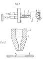
- the gas ion source comprises a needle assembly 1 and extractor 2 which are carried on a mounting flange 3 by means of a pair of spaced pillars 4.
- the needle assembly comprises a hollow needle 5 made of refractory metal such as tungsten which is mounted in an insulating support 6. Gas is supplied to the interior passage 7 within the needle 5 via a tube 8 which passes through the flange 3. If desired preheating of the gas may be carried out by means of a heater (not shown) associated with the tube 8. Such preheating may be desirable in certain circumstances in order to prevent the condensation of volatile vapours in the tube.
- the needle tapers at its free end to a diameter typically of 75yc.
- the outlet end of passage 7 likewise tapers at the free end of the needle to provide a constriction having a diameter typically of 25 ⁇ .
- the extractor 2 comprises a flat circular extractor electrode 9 having a through-aperture 10, typically of 100 ⁇ . diameter, at its centre.
- the electrode 9 is supported by a generally cylindrical electrode support member 11 in such a way that the aperture 10 lies directly in front of the exit of the needle 5.
- the distance between the extractor electrode and the tip of the needle is typically lmm.
- the extractor electrode and needle are connected by way of pillars 4 to respective terminals of an electrical power supply unit (not shown) so that, in use, the needle has a positive potential with respect to the extractor electrode.
- the voltage applied between the needle and the extractor electrode is typically between 5,000 and 10,000 volts.
- a suitable gas such as argon is passed along the tube 8 to the passage 7 within the needle.
- the constricted portion at the mouth of the passage 7 has a self-regulating effect and ensures that a well defined stream of gas emerges into the space between the needle and the extractor electrode.
- the sudden emergence of gas from the constricted portion of passage 7 into the relatively wide space within the extractor results in a localised region of relatively high pressure at the exit of the passage 7 and it is in this high pressure region, subjected as it is to the electric field existing between the needle and the extractor electrode, that the ionisation of the gas takes place.
- the ions are created in a highly localised self contained and self sustaining discharge which is initiated by some random external event.
- the ion source is used in an evacuated atmosphere, with ambient pressures no greater than 10- 5 mm Hg.
- ambient pressure is 1 millionth of an atmosphere while the pressure in the localised high pressure region adjacent the exit to the passage 7 is typically k atmosphere. This leads to a very considerable pressure gradient in the 1 mm space between the tip of the needle and the extractor electrode.
- FIG. 3 shows a typical experimental test set-up.
- the ion source is mounted within a vacuum chamber 12 above a collector electrode 13. Gas to be ionised is supplied to tube 8 form a cylinder 14, the inlet gas pressure being monitored by a gauge 15.
- An electrical power supply 16 has positive and negative outputs connected to the needle 5 and extractor 2 respectively in order to produce a high electric field between the two.
- the collector electrode is likewise connected to the negative output, via a microammeter.
- the ion beam is drawn out of the ion source by means of the electric field existing between the extractor electrode and the needle.
- the extractor electrode is intended to provide the high electrical gradient needed for ionisation and also to provide the acceleration of the ion beam as it leaves the region of ionisation.
- the collector electrode is intended to represent a target workpiece which is to be bombarded, and is not part of the ion source per se.
- the energy of the ion beam as it strikes the collector electrode is dependent upon the magnitude of the voltage between the needle and the collector electrode.
- the potential of the collector electrode will be capable of adjustment independently of that of the extractor electrode in order to take account of varying requirements in use.
- the ion source described above can be used with a wide variety of gases and volatile metals. Examples are argon, helium, neon, nitrogen, hydrogen, deuterium, oxygen or volatile arsenic or boron. In the case of oxygen, problems can arise due to erosion of the needle, and the source should be operated at a lower current to reduce this.
- the gas pressure, as recorded on gauge 15, is in the region of 120 to 280 mm Hg.
- the ion source described above will produce a reliable high intensity beam of ions and finds wide application in industry in particular for material processing and surface analysis.
- the ion source is mounted within a vacuum chamber and the beam of ions for example argon ions, produced by the source is directed at the target material.
- the resultant ion bombardment will sputter or etch away material from the target. Electrons and ions released by the target during ion bombardment can be analysed to determine the existence and concentration of the various elements present.
Landscapes
- Chemical & Material Sciences (AREA)
- Engineering & Computer Science (AREA)
- Combustion & Propulsion (AREA)
- Electron Sources, Ion Sources (AREA)
- Physical Or Chemical Processes And Apparatus (AREA)
Applications Claiming Priority (2)
| Application Number | Priority Date | Filing Date | Title |
|---|---|---|---|
| GB8038922 | 1980-12-04 | ||
| GB8038922 | 1980-12-04 |
Publications (1)
| Publication Number | Publication Date |
|---|---|
| EP0056899A1 true EP0056899A1 (de) | 1982-08-04 |
Family
ID=10517754
Family Applications (1)
| Application Number | Title | Priority Date | Filing Date |
|---|---|---|---|
| EP19810305685 Ceased EP0056899A1 (de) | 1980-12-04 | 1981-12-02 | Gasionenquelle |
Country Status (2)
| Country | Link |
|---|---|
| EP (1) | EP0056899A1 (de) |
| JP (1) | JPS57132654A (de) |
Cited By (4)
| Publication number | Priority date | Publication date | Assignee | Title |
|---|---|---|---|---|
| EP0063493B1 (de) * | 1981-04-20 | 1985-09-04 | Inoue-Japax Research Incorporated | Verfahren und Vorrichtung für die Bearbeitung von Werkstücken mittels Ionen |
| EP0346271A1 (de) * | 1988-06-10 | 1989-12-13 | Sri International | Nach der Mikroelektronik aufgebauter Feldionisator und Verfahren zur Herstellung desselben |
| EP1826809A1 (de) * | 2006-02-22 | 2007-08-29 | FEI Company | Partikel-Optisches Gerät ausgestattet mit einer Gasionenquelle |
| US9941094B1 (en) | 2017-02-01 | 2018-04-10 | Fei Company | Innovative source assembly for ion beam production |
Citations (4)
| Publication number | Priority date | Publication date | Assignee | Title |
|---|---|---|---|---|
| US3309873A (en) * | 1964-08-31 | 1967-03-21 | Electro Optical Systems Inc | Plasma accelerator using hall currents |
| US3955090A (en) * | 1973-12-27 | 1976-05-04 | Exxon Nuclear Company, Inc. | Sputtered particle flow source for isotopically selective ionization |
| FR2344116A1 (fr) * | 1976-03-11 | 1977-10-07 | Schwerionenforsch Gmbh | Source de production d'ions a charge simple ou multiple |
| DE2701395B2 (de) * | 1977-01-14 | 1979-03-29 | Dr. Franzen Analysentechnik Gmbh & Co Kg, 2800 Bremen | Ionenquelle für die chemische Ionisierung von Atomen und Molekülen |
-
1981
- 1981-12-02 EP EP19810305685 patent/EP0056899A1/de not_active Ceased
- 1981-12-04 JP JP56194648A patent/JPS57132654A/ja active Pending
Patent Citations (4)
| Publication number | Priority date | Publication date | Assignee | Title |
|---|---|---|---|---|
| US3309873A (en) * | 1964-08-31 | 1967-03-21 | Electro Optical Systems Inc | Plasma accelerator using hall currents |
| US3955090A (en) * | 1973-12-27 | 1976-05-04 | Exxon Nuclear Company, Inc. | Sputtered particle flow source for isotopically selective ionization |
| FR2344116A1 (fr) * | 1976-03-11 | 1977-10-07 | Schwerionenforsch Gmbh | Source de production d'ions a charge simple ou multiple |
| DE2701395B2 (de) * | 1977-01-14 | 1979-03-29 | Dr. Franzen Analysentechnik Gmbh & Co Kg, 2800 Bremen | Ionenquelle für die chemische Ionisierung von Atomen und Molekülen |
Cited By (8)
| Publication number | Priority date | Publication date | Assignee | Title |
|---|---|---|---|---|
| EP0063493B1 (de) * | 1981-04-20 | 1985-09-04 | Inoue-Japax Research Incorporated | Verfahren und Vorrichtung für die Bearbeitung von Werkstücken mittels Ionen |
| EP0346271A1 (de) * | 1988-06-10 | 1989-12-13 | Sri International | Nach der Mikroelektronik aufgebauter Feldionisator und Verfahren zur Herstellung desselben |
| EP1826809A1 (de) * | 2006-02-22 | 2007-08-29 | FEI Company | Partikel-Optisches Gerät ausgestattet mit einer Gasionenquelle |
| EP1830383A3 (de) * | 2006-02-22 | 2007-12-19 | FEI Company | Mit einer Gasionenquelle ausgestattete teilchenoptische Vorrichtung |
| CN101026080B (zh) * | 2006-02-22 | 2010-04-21 | Fei公司 | 装备有气体离子源的粒子光学设备 |
| US7772564B2 (en) | 2006-02-22 | 2010-08-10 | Fei Company | Particle-optical apparatus equipped with a gas ion source |
| US9941094B1 (en) | 2017-02-01 | 2018-04-10 | Fei Company | Innovative source assembly for ion beam production |
| US10651005B2 (en) | 2017-02-01 | 2020-05-12 | Fei Company | Innovative source assembly for ion beam production |
Also Published As
| Publication number | Publication date |
|---|---|
| JPS57132654A (en) | 1982-08-17 |
Similar Documents
| Publication | Publication Date | Title |
|---|---|---|
| JP4511039B2 (ja) | 準安定原子衝撃源 | |
| US5017835A (en) | High-frequency ion source | |
| US10236169B2 (en) | Ionization device with mass spectrometer therewith | |
| US3408283A (en) | High current duoplasmatron having an apertured anode positioned in the low pressure region | |
| US2892114A (en) | Continuous plasma generator | |
| US3955091A (en) | Method and apparatus for extracting well-formed, high current ion beams from a plasma source | |
| GB2296369A (en) | Radio frequency ion source | |
| AU589349B2 (en) | Dynamic electron emitter | |
| EP0056899A1 (de) | Gasionenquelle | |
| US4985657A (en) | High flux ion gun apparatus and method for enhancing ion flux therefrom | |
| JPH07183001A (ja) | イオン性アルミニウムの製造方法及び装置 | |
| JP4977557B2 (ja) | イオン源 | |
| JPS62278736A (ja) | 電子ビ−ム励起イオン源 | |
| GB862835A (en) | A device for producing energetic ions | |
| JPH06215712A (ja) | イオン加速装置 | |
| GB1398167A (en) | High pressure ion sources | |
| JP4571003B2 (ja) | クラスターイオンビーム装置 | |
| JP2879342B2 (ja) | 電子ビーム励起イオン源 | |
| US3446959A (en) | Method of and apparatus for producing particles in a metastable state | |
| GB1371104A (en) | Methods of and apparatus for analysing mixtures | |
| Orlikov et al. | Methods for increasing the efficiency of electron beam extraction through a gas-dynamic window | |
| JPH06338279A (ja) | 電子銃 | |
| JPS63221540A (ja) | 電子ビ−ム励起イオン源 | |
| JPS6217931A (ja) | イオン源 | |
| JPH0620631A (ja) | プラズマ電子銃 |
Legal Events
| Date | Code | Title | Description |
|---|---|---|---|
| PUAI | Public reference made under article 153(3) epc to a published international application that has entered the european phase |
Free format text: ORIGINAL CODE: 0009012 |
|
| AK | Designated contracting states |
Designated state(s): AT BE CH DE FR GB IT LU NL SE |
|
| 17P | Request for examination filed |
Effective date: 19830204 |
|
| STAA | Information on the status of an ep patent application or granted ep patent |
Free format text: STATUS: THE APPLICATION HAS BEEN REFUSED |
|
| 18R | Application refused |
Effective date: 19850624 |
|
| IECL | Ie: translation for ep claims filed | ||
| RIN1 | Information on inventor provided before grant (corrected) |
Inventor name: PASHLEY, NEIL ARTHUR |