EP0056910A1 - Zusammenbauten zum Erzeugen unterbrechungsfreier elektrischer Wechselstromenergie mit konstanter Frequenz - Google Patents
Zusammenbauten zum Erzeugen unterbrechungsfreier elektrischer Wechselstromenergie mit konstanter Frequenz Download PDFInfo
- Publication number
- EP0056910A1 EP0056910A1 EP81400082A EP81400082A EP0056910A1 EP 0056910 A1 EP0056910 A1 EP 0056910A1 EP 81400082 A EP81400082 A EP 81400082A EP 81400082 A EP81400082 A EP 81400082A EP 0056910 A1 EP0056910 A1 EP 0056910A1
- Authority
- EP
- European Patent Office
- Prior art keywords
- shaft
- speed
- alternator
- assembly according
- pinion
- Prior art date
- Legal status (The legal status is an assumption and is not a legal conclusion. Google has not performed a legal analysis and makes no representation as to the accuracy of the status listed.)
- Withdrawn
Links
Images
Classifications
-
- H—ELECTRICITY
- H02—GENERATION; CONVERSION OR DISTRIBUTION OF ELECTRIC POWER
- H02J—ELECTRIC POWER NETWORKS; CIRCUIT ARRANGEMENTS OR SYSTEMS FOR SUPPLYING OR DISTRIBUTING ELECTRIC POWER; SYSTEMS FOR STORING ELECTRIC ENERGY
- H02J9/00—Circuit arrangements for emergency or stand-by power supply, e.g. for emergency lighting
- H02J9/04—Circuit arrangements for emergency or stand-by power supply, e.g. for emergency lighting in which the distribution system is disconnected from the normal source and connected to a standby source
- H02J9/06—Circuit arrangements for emergency or stand-by power supply, e.g. for emergency lighting in which the distribution system is disconnected from the normal source and connected to a standby source with automatic change-over, e.g. UPS systems
- H02J9/066—Circuit arrangements for emergency or stand-by power supply, e.g. for emergency lighting in which the distribution system is disconnected from the normal source and connected to a standby source with automatic change-over, e.g. UPS systems characterised by the use of dynamo-electric machines
-
- H—ELECTRICITY
- H02—GENERATION; CONVERSION OR DISTRIBUTION OF ELECTRIC POWER
- H02J—ELECTRIC POWER NETWORKS; CIRCUIT ARRANGEMENTS OR SYSTEMS FOR SUPPLYING OR DISTRIBUTING ELECTRIC POWER; SYSTEMS FOR STORING ELECTRIC ENERGY
- H02J3/00—Circuit arrangements for AC mains or AC distribution networks
- H02J3/28—Arrangements for balancing of the load in networks by storage of energy
- H02J3/30—Arrangements for balancing of the load in networks by storage of energy using dynamo-electric machines coupled to flywheels
-
- H—ELECTRICITY
- H02—GENERATION; CONVERSION OR DISTRIBUTION OF ELECTRIC POWER
- H02J—ELECTRIC POWER NETWORKS; CIRCUIT ARRANGEMENTS OR SYSTEMS FOR SUPPLYING OR DISTRIBUTING ELECTRIC POWER; SYSTEMS FOR STORING ELECTRIC ENERGY
- H02J9/00—Circuit arrangements for emergency or stand-by power supply, e.g. for emergency lighting
- H02J9/04—Circuit arrangements for emergency or stand-by power supply, e.g. for emergency lighting in which the distribution system is disconnected from the normal source and connected to a standby source
- H02J9/06—Circuit arrangements for emergency or stand-by power supply, e.g. for emergency lighting in which the distribution system is disconnected from the normal source and connected to a standby source with automatic change-over, e.g. UPS systems
-
- H—ELECTRICITY
- H02—GENERATION; CONVERSION OR DISTRIBUTION OF ELECTRIC POWER
- H02J—ELECTRIC POWER NETWORKS; CIRCUIT ARRANGEMENTS OR SYSTEMS FOR SUPPLYING OR DISTRIBUTING ELECTRIC POWER; SYSTEMS FOR STORING ELECTRIC ENERGY
- H02J9/00—Circuit arrangements for emergency or stand-by power supply, e.g. for emergency lighting
- H02J9/04—Circuit arrangements for emergency or stand-by power supply, e.g. for emergency lighting in which the distribution system is disconnected from the normal source and connected to a standby source
- H02J9/06—Circuit arrangements for emergency or stand-by power supply, e.g. for emergency lighting in which the distribution system is disconnected from the normal source and connected to a standby source with automatic change-over, e.g. UPS systems
- H02J9/08—Circuit arrangements for emergency or stand-by power supply, e.g. for emergency lighting in which the distribution system is disconnected from the normal source and connected to a standby source with automatic change-over, e.g. UPS systems requiring starting of a prime-mover
-
- Y—GENERAL TAGGING OF NEW TECHNOLOGICAL DEVELOPMENTS; GENERAL TAGGING OF CROSS-SECTIONAL TECHNOLOGIES SPANNING OVER SEVERAL SECTIONS OF THE IPC; TECHNICAL SUBJECTS COVERED BY FORMER USPC CROSS-REFERENCE ART COLLECTIONS [XRACs] AND DIGESTS
- Y02—TECHNOLOGIES OR APPLICATIONS FOR MITIGATION OR ADAPTATION AGAINST CLIMATE CHANGE
- Y02E—REDUCTION OF GREENHOUSE GAS [GHG] EMISSIONS, RELATED TO ENERGY GENERATION, TRANSMISSION OR DISTRIBUTION
- Y02E60/00—Enabling technologies; Technologies with a potential or indirect contribution to GHG emissions mitigation
- Y02E60/16—Mechanical energy storage, e.g. flywheels or pressurised fluids
Definitions
- the invention relates to assemblies or "groups" intended to generate alternative electrical energy at constant frequency and without interruption, as is required for the supply of certain electrical equipment such as computers, computers, telecommunications systems, systems navigation, radars, test platforms, etc.
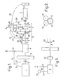
- the correction means comprise on the one hand a differential train and on the other hand a regulation system capable of acting automatically on the speed of rotation of a rotary regulating element. said train, during permutations of the energy source, so as to maintain substantially constant and equal to a set value the speed of the alternator shaft.
- the differential train is interposed between the shaft A of the flywheel and the shaft B of the alternator, this train comprising a first pinion integral with the shaft A, a second pinion integral with the shaft B, and an assembly, comprising the regulating element, capable of transmitting the rotations from the first pinion to the second according to a ratio which varies - and preferably increases - with the speed of rotation of said regulating element, and in that the regulation system is driven by tree A.
- the invention includes, apart from these main provisions, certain other provisions which are preferably used at the same time and which will be more explicitly discussed below.
- This load Z is of a type requiring a permanent supply at constant frequency F, that is to say generally regulated to within 1% and without interruption.
- the motor 4 In normal times, that is to say when the network supplies current, the motor 4 is supplied by this network, and therefore driven at a substantially constant speed, for example close to 1,500 rpm, to the nearest slip which is in the range of 1 to 2 % .
- the flywheel 3 is also driven by this motor 4.
- the clutch 2 is open and the engine 1 is stopped in the standby state (preheated).
- the energy stored by the flywheel 3 is then applied to the motor 1 and causes it to speed up in a few seconds, and at the end of this speeding up, it is this motor which ensures the training of the whole group to the initial speed.
- the speed of rotation of the flywheel 3, which is that of the motor shaft 4 decreases by approximately 10 to 15% in 3 or 4 seconds, then rises to its initial value in a time of l '' from 15 to 20 seconds.
- the present invention aims at another solution of the same problem.
- external means are provided, driven by the shaft A, capable of giving the speed N R a value such that the speed N S remains equal to a set value N O at all times despite the variations in speed.
- N E external means are provided, driven by the shaft A, capable of giving the speed N R a value such that the speed N S remains equal to a set value N O at all times despite the variations in speed.
- the speed NE at cruising speed, that is to say outside the periods of permutation of the drive mode of the shaft 1, the speed NE generally being within a range of ⁇ 2% around the speed N 0 , taking into account the nature of the drive motor, the speed N R remains very low, namely of the order of a few revolutions / minute.
- the mobile assembly thereof comprises a cage 14 mounted idly on at least one of the shafts A and B, cage carrying two cylindrical pinions with axes parallel to the axes of said shafts, namely a third pinion 15 engaged with pinion 12 and a fourth pinion 16 engaged with pinion 15 and with pinion 13, these pinions 12 and 13 then also being cylindrical pinions .
- the pinions 12, 15 and 16 have the same number of teeth and the pinion 13 has a slightly higher number of teeth, these two numbers being for example 30 and 31 respectively, or again 33 and 34 , from 34 and 35, or from 50 and 51.
- the pinion 12 having for example a number of teeth greater than that of the pinion 13 and the pinion 15, a number of teeth less than that of the pinion 16.
- This metering device 25 is continuously adjusted automatically so as to maintain the speed of rotation N S of the shaft B equal to the set value N o , for example to within 1%.
- an electronic assembly 26 is used which is capable of developing control instructions symbolized by the arrow 27 as a function of both the actual speed of rotation N of the shaft B, speed detected by a tachometer 28 (information symbolized by the arrow 29) and a rigorously stabilized frequency reference, a function of the value N O , a reference whose introduction into the assembly 26 is symbolized by the arrow 30.
- the motor 4 is supplied by the network and its rotor turns at a speed NE slightly lower than N O , for example of the order of 1,460 revolutions / minute.
- the NE speed When taking over, the NE speed begins to decrease for 3 to 4 seconds, to a minimum of around 1,350 rpm (first phase), then gradually returns to its initial value in 15 to 20 seconds (second phase) ).
- the speed N s also tends to decrease, but the instantaneous comparison between this speed, taken at 28, 29 and the reference speed N 0 generates an error signal acting immediately on the metering device 25, in a direction and with an amplitude such that the cage 14 is driven at a regulation speed N R capable of compensating for said error.
- this speed N R increases to its maximum value which is around 100 revolutions / minute.
- the supply of the load Z was therefore ensured without interruption and without modification of frequency throughout the duration of the permutation of the drive mode of the shaft A.
- this drive could be provided by different means, for example using an assembly electric generator-engine of the Ward Leonard type, the hydraulic pump 18, the hydraulic motor 21, the hydraulic circuit 24 and the metering device 25 of the previous solution then being replaced respectively by an electric generator, an electric motor, an electric circuit and a rheostat or equivalent adjustment device.
- FIG. 3 there is illustrated in FIG. 3 an alternative embodiment for said group.
- This group also includes a flywheel 3 secured to the shaft A and an electric motor 4, in particular of the asynchronous type, normally supplied by the network 5 through the circuit breaker 6.
- this engine 4 is connected to the flywheel by a slip coupler 33, in particular hydraulic, the heat engine not being provided for coupling to the rotor of this engine 4 by a clutch: this heat engine is here that of a generator 34 and the relay of the electrical supply of the motor 4 from the network 5 is taken by another electrical supply provided from said group 34 through a switch 35 which closes automatically when the circuit breaker 6 opens and vice versa (arrow 36 ).
- the sliding of the coupler 33 makes it possible to rapidly climb the asynchronous motor 4 to its nominal speed during starts, even before the steering wheel 3 has reached its normal cruising speed.
- the temporary slowing down of the shaft A during a change in the drive mode of this shaft is due to the time necessary for the generating set 34 to start up from its stopping, duration which is generally about ten seconds.
- the engine 4 of the two previous embodiments is eliminated and, in normal operation, the alternator 7 is driven by the network 5 and itself drives the flywheel 3, via the train 11 and the corrector assembly 17, while in the event of a power cut, the alternator drive relay is taken up by the flywheel, then by a heat engine then engaged on this flywheel.
- the invention is in no way limited to those of its modes of application and embodiments which have been more especially envisaged: breaststroke, on the contrary, all variants, in particular those where the cylindrical pinions 12 and 13 of the embodiment described above would be replaced by two bevel gears, the cylindrical gears 15 and 16 then being replaced themselves by a single bevel gear satellite in engagement with the other two, the axis of the latter pinion being inclined at an angle close to 90 ° to those of the shafts A and B and being mounted idly on a cage of the type of the cage 14 above.
Landscapes
- Engineering & Computer Science (AREA)
- Power Engineering (AREA)
- Business, Economics & Management (AREA)
- Emergency Management (AREA)
- Auxiliary Drives, Propulsion Controls, And Safety Devices (AREA)
Priority Applications (3)
| Application Number | Priority Date | Filing Date | Title |
|---|---|---|---|
| FR7919498A FR2462803A1 (fr) | 1979-07-27 | 1979-07-27 | Perfectionnements aux ensembles pour engendrer une energie electrique alternative a frequence constante et sans coupure |
| OA57306A OA06728A (fr) | 1979-07-27 | 1981-01-21 | Perfectionnements aux ensembles pour engendrer une énergie électrique alternative à fréquence constante et sans coupure. |
| EP81400082A EP0056910A1 (de) | 1979-07-27 | 1981-01-21 | Zusammenbauten zum Erzeugen unterbrechungsfreier elektrischer Wechselstromenergie mit konstanter Frequenz |
Applications Claiming Priority (2)
| Application Number | Priority Date | Filing Date | Title |
|---|---|---|---|
| FR7919498A FR2462803A1 (fr) | 1979-07-27 | 1979-07-27 | Perfectionnements aux ensembles pour engendrer une energie electrique alternative a frequence constante et sans coupure |
| EP81400082A EP0056910A1 (de) | 1979-07-27 | 1981-01-21 | Zusammenbauten zum Erzeugen unterbrechungsfreier elektrischer Wechselstromenergie mit konstanter Frequenz |
Publications (1)
| Publication Number | Publication Date |
|---|---|
| EP0056910A1 true EP0056910A1 (de) | 1982-08-04 |
Family
ID=26082748
Family Applications (1)
| Application Number | Title | Priority Date | Filing Date |
|---|---|---|---|
| EP81400082A Withdrawn EP0056910A1 (de) | 1979-07-27 | 1981-01-21 | Zusammenbauten zum Erzeugen unterbrechungsfreier elektrischer Wechselstromenergie mit konstanter Frequenz |
Country Status (3)
| Country | Link |
|---|---|
| EP (1) | EP0056910A1 (de) |
| FR (1) | FR2462803A1 (de) |
| OA (1) | OA06728A (de) |
Cited By (2)
| Publication number | Priority date | Publication date | Assignee | Title |
|---|---|---|---|---|
| EP0058720B1 (de) * | 1980-09-02 | 1985-07-24 | MUCSY, Endre | Hilfsenergiespeisung, insbesondere eine elektrische energiespeisung |
| CN114257028A (zh) * | 2021-11-16 | 2022-03-29 | 国家电投集团科学技术研究院有限公司 | 具有电磁耦合器的飞轮储能系统 |
Citations (7)
| Publication number | Priority date | Publication date | Assignee | Title |
|---|---|---|---|---|
| FR1104467A (fr) * | 1954-05-10 | 1955-11-21 | Alsthom Cgee | Nouveau procédé de mise en service rapide de groupes de secours par volants d'inertie |
| FR68029E (fr) * | 1955-09-15 | 1958-03-27 | Cfcmug | Dispositif de régulation de la fréquence d'un groupe convertisseur |
| DE1073087B (de) * | 1960-01-14 | Siemens-Schuckertwerke Aktiengesellschaft, Berlin Und Erlangen | Elektrische Anlage mit Notstromerzeuger | |
| GB867839A (en) * | 1957-03-01 | 1961-05-10 | Blackstone & Co Ltd | Improvements in stand-by electric generators |
| US3221172A (en) * | 1962-08-29 | 1965-11-30 | John G Stevens | No-break power supply |
| US3558901A (en) * | 1969-02-24 | 1971-01-26 | Charles J Jacobus | Standby power system |
| FR2278043A1 (fr) * | 1974-07-08 | 1976-02-06 | Serals Engineering | Systeme d'alimentation et de climatisation d'un centre de trai tement informatique |
-
1979
- 1979-07-27 FR FR7919498A patent/FR2462803A1/fr active Granted
-
1981
- 1981-01-21 OA OA57306A patent/OA06728A/xx unknown
- 1981-01-21 EP EP81400082A patent/EP0056910A1/de not_active Withdrawn
Patent Citations (7)
| Publication number | Priority date | Publication date | Assignee | Title |
|---|---|---|---|---|
| DE1073087B (de) * | 1960-01-14 | Siemens-Schuckertwerke Aktiengesellschaft, Berlin Und Erlangen | Elektrische Anlage mit Notstromerzeuger | |
| FR1104467A (fr) * | 1954-05-10 | 1955-11-21 | Alsthom Cgee | Nouveau procédé de mise en service rapide de groupes de secours par volants d'inertie |
| FR68029E (fr) * | 1955-09-15 | 1958-03-27 | Cfcmug | Dispositif de régulation de la fréquence d'un groupe convertisseur |
| GB867839A (en) * | 1957-03-01 | 1961-05-10 | Blackstone & Co Ltd | Improvements in stand-by electric generators |
| US3221172A (en) * | 1962-08-29 | 1965-11-30 | John G Stevens | No-break power supply |
| US3558901A (en) * | 1969-02-24 | 1971-01-26 | Charles J Jacobus | Standby power system |
| FR2278043A1 (fr) * | 1974-07-08 | 1976-02-06 | Serals Engineering | Systeme d'alimentation et de climatisation d'un centre de trai tement informatique |
Cited By (3)
| Publication number | Priority date | Publication date | Assignee | Title |
|---|---|---|---|---|
| EP0058720B1 (de) * | 1980-09-02 | 1985-07-24 | MUCSY, Endre | Hilfsenergiespeisung, insbesondere eine elektrische energiespeisung |
| CN114257028A (zh) * | 2021-11-16 | 2022-03-29 | 国家电投集团科学技术研究院有限公司 | 具有电磁耦合器的飞轮储能系统 |
| CN114257028B (zh) * | 2021-11-16 | 2024-04-30 | 国家电投集团科学技术研究院有限公司 | 具有电磁耦合器的飞轮储能系统 |
Also Published As
| Publication number | Publication date |
|---|---|
| FR2462803A1 (fr) | 1981-02-13 |
| FR2462803B1 (de) | 1984-12-07 |
| OA06728A (fr) | 1982-06-30 |
Similar Documents
| Publication | Publication Date | Title |
|---|---|---|
| EP0414782B1 (de) | Stufenlos verstellbares zahnradgetriebe | |
| EP0179713B1 (de) | Vorrichtung für die Steuerung der Brennstoffmenge, z.B. für Gasturbinen | |
| EP0782940B1 (de) | Antriebssystem für ein Hybrid angetriebenes Kraftfahrzeug und zugehöriges Steuerungsverfahren | |
| CH687307A5 (fr) | Ensemble de propulsion d'un véhicule. | |
| EP0652835B1 (de) | Kraftfahrzeug mit elektrischem antrieb | |
| FR2540647A1 (fr) | Dispositif de pilotage automatique d'embrayage | |
| FR2590420A1 (fr) | Dispositif limiteur du courant d'alimentation pour un moteur electrique a courant continu, et moteur electrique equipe d'un tel dispositif | |
| LU83611A1 (fr) | Appareil et procede pour produire de l'energie electrique en utilisant l'energie eolienne | |
| EP0044834B1 (de) | Antriebseinheit für mit einem thermischen motor bis zu niedrigen drehzahlen mit hilfe einer elektrischen maschine angetriebenen kraftfahrzeug | |
| BE1014275A3 (fr) | Appareil de transmission de vitesses. | |
| EP0056910A1 (de) | Zusammenbauten zum Erzeugen unterbrechungsfreier elektrischer Wechselstromenergie mit konstanter Frequenz | |
| EP1293854B1 (de) | Motorgeschwindigkeitsregelsystem eines Hubschraubers | |
| WO2013083885A1 (fr) | Dispositif de transmission, groupe motopropulseur, accumulateur d'energie, et vehicule ainsi equipe | |
| EP0642209A1 (de) | Startvorrichtung, für eine Turbine, insbesondere eine Gasturbine | |
| FR2495855A1 (fr) | Moteur electrique asynchrone, dispositif de commande de l'alimentation d'un tel moteur et circulateur comportant un tel moteur | |
| EP1068088A1 (de) | Hilsverfahren bei der leerlaufdrehzahlregelung eines hybridfahrzeuges | |
| BE1031862B1 (fr) | Procédé de contrôle d'un groupe motopropulseur, groupe motopropulseur et véhicule à pédales | |
| FR2748781A1 (fr) | Procede et dispositif pour entrainer une pompe de carburant | |
| EP4499442B1 (de) | Kraftfahrzeug mit elektrischem antrieb und verfahren zum steuern des kraftfahrzeugs | |
| EP3814167A1 (de) | Verfahren zur steuerung einer rotierenden elektrischen maschine zum ausgleich von drehmomentschwingungen einer antriebskette eines kraftfahrzeuges | |
| EP0789439A1 (de) | Vorrichtung zur Regelung der Ladespannung einer Batterie die durch einen Generator geladen wird in Abhängigkeit von einer Bezugsspannung und der Drehgeschwindigkeit des Generators | |
| EP0267990A1 (de) | Regeleinrichtung für ein Fahrzeug mit elektrischer Kraftübertragung | |
| EP4252336A1 (de) | Pumpenbetätigungsvorrichtung und zugehöriges pumpsystem, flugzeug und kraftstoffversorgungsverfahren | |
| BE358037A (de) | ||
| HK40117831A (en) | Vehicle with electric drive and control method for such vehicle |
Legal Events
| Date | Code | Title | Description |
|---|---|---|---|
| PUAI | Public reference made under article 153(3) epc to a published international application that has entered the european phase |
Free format text: ORIGINAL CODE: 0009012 |
|
| AK | Designated contracting states |
Designated state(s): BE CH DE GB IT NL SE |
|
| 17P | Request for examination filed |
Effective date: 19820823 |
|
| STAA | Information on the status of an ep patent application or granted ep patent |
Free format text: STATUS: THE APPLICATION IS DEEMED TO BE WITHDRAWN |
|
| 18D | Application deemed to be withdrawn |
Effective date: 19841110 |
|
| RIN1 | Information on inventor provided before grant (corrected) |
Inventor name: GEORGES, JEAN-CLAUDE |