EP0056920A1 - Optische Einrichtung zur Aufzeichnung und Wiedergabe von einem Informationsträger mit zwei Laserquellen verschiedener Wellenlängen - Google Patents
Optische Einrichtung zur Aufzeichnung und Wiedergabe von einem Informationsträger mit zwei Laserquellen verschiedener Wellenlängen Download PDFInfo
- Publication number
- EP0056920A1 EP0056920A1 EP81402053A EP81402053A EP0056920A1 EP 0056920 A1 EP0056920 A1 EP 0056920A1 EP 81402053 A EP81402053 A EP 81402053A EP 81402053 A EP81402053 A EP 81402053A EP 0056920 A1 EP0056920 A1 EP 0056920A1
- Authority
- EP
- European Patent Office
- Prior art keywords
- optical device
- dichroic
- reading
- recording
- rays
- Prior art date
- Legal status (The legal status is an assumption and is not a legal conclusion. Google has not performed a legal analysis and makes no representation as to the accuracy of the status listed.)
- Withdrawn
Links
- 230000003287 optical effect Effects 0.000 title claims abstract description 36
- 239000002131 composite material Substances 0.000 claims abstract description 22
- 230000005855 radiation Effects 0.000 claims abstract description 19
- 230000010287 polarization Effects 0.000 claims description 21
- 238000000926 separation method Methods 0.000 claims description 12
- 239000004065 semiconductor Substances 0.000 claims description 7
- 210000001747 pupil Anatomy 0.000 claims description 6
- 210000003128 head Anatomy 0.000 description 7
- 201000009310 astigmatism Diseases 0.000 description 5
- 238000001514 detection method Methods 0.000 description 5
- 230000004075 alteration Effects 0.000 description 4
- 238000006073 displacement reaction Methods 0.000 description 3
- 238000000034 method Methods 0.000 description 3
- 230000008901 benefit Effects 0.000 description 2
- 230000004048 modification Effects 0.000 description 2
- 238000012986 modification Methods 0.000 description 2
- 241000269908 Platichthys flesus Species 0.000 description 1
- 239000000969 carrier Substances 0.000 description 1
- 238000010586 diagram Methods 0.000 description 1
- 210000000887 face Anatomy 0.000 description 1
- 230000006870 function Effects 0.000 description 1
- 230000010365 information processing Effects 0.000 description 1
- 230000015654 memory Effects 0.000 description 1
- 230000002093 peripheral effect Effects 0.000 description 1
- 230000001902 propagating effect Effects 0.000 description 1
- 230000009467 reduction Effects 0.000 description 1
- 239000011435 rock Substances 0.000 description 1
- 238000004381 surface treatment Methods 0.000 description 1
Images

Classifications
-
- G—PHYSICS
- G11—INFORMATION STORAGE
- G11B—INFORMATION STORAGE BASED ON RELATIVE MOVEMENT BETWEEN RECORD CARRIER AND TRANSDUCER
- G11B7/00—Recording or reproducing by optical means, e.g. recording using a thermal beam of optical radiation by modifying optical properties or the physical structure, reproducing using an optical beam at lower power by sensing optical properties; Record carriers therefor
- G11B7/12—Heads, e.g. forming of the optical beam spot or modulation of the optical beam
-
- G—PHYSICS
- G11—INFORMATION STORAGE
- G11B—INFORMATION STORAGE BASED ON RELATIVE MOVEMENT BETWEEN RECORD CARRIER AND TRANSDUCER
- G11B7/00—Recording or reproducing by optical means, e.g. recording using a thermal beam of optical radiation by modifying optical properties or the physical structure, reproducing using an optical beam at lower power by sensing optical properties; Record carriers therefor
- G11B7/12—Heads, e.g. forming of the optical beam spot or modulation of the optical beam
- G11B7/125—Optical beam sources therefor, e.g. laser control circuitry specially adapted for optical storage devices; Modulators, e.g. means for controlling the size or intensity of optical spots or optical traces
- G11B7/127—Lasers; Multiple laser arrays
- G11B7/1275—Two or more lasers having different wavelengths
-
- G—PHYSICS
- G11—INFORMATION STORAGE
- G11B—INFORMATION STORAGE BASED ON RELATIVE MOVEMENT BETWEEN RECORD CARRIER AND TRANSDUCER
- G11B7/00—Recording or reproducing by optical means, e.g. recording using a thermal beam of optical radiation by modifying optical properties or the physical structure, reproducing using an optical beam at lower power by sensing optical properties; Record carriers therefor
- G11B7/12—Heads, e.g. forming of the optical beam spot or modulation of the optical beam
- G11B7/135—Means for guiding the beam from the source to the record carrier or from the record carrier to the detector
- G11B7/1362—Mirrors
-
- G—PHYSICS
- G11—INFORMATION STORAGE
- G11B—INFORMATION STORAGE BASED ON RELATIVE MOVEMENT BETWEEN RECORD CARRIER AND TRANSDUCER
- G11B7/00—Recording or reproducing by optical means, e.g. recording using a thermal beam of optical radiation by modifying optical properties or the physical structure, reproducing using an optical beam at lower power by sensing optical properties; Record carriers therefor
- G11B7/12—Heads, e.g. forming of the optical beam spot or modulation of the optical beam
- G11B7/135—Means for guiding the beam from the source to the record carrier or from the record carrier to the detector
- G11B7/1365—Separate or integrated refractive elements, e.g. wave plates
Definitions
- the invention relates to an optical device for recording and reading information media.
- the invention relates more particularly to recorder-reader systems in which the information medium is a disc.
- the information medium is a disc.
- These systems can be used as mass storage for digital data processing sets.
- These systems must allow random access to a predetermined part of the recorded data, for example a block of binary words of fixed or variable length.
- the speed of calculation of the information processing units requires numerous exchanges between the peripheral memories and these calculation units. It is therefore necessary that the access to a predetermined track of a mobile information medium takes place in the shortest possible time, both for reading pre-recorded information, and for recording such information, whatever the position of this track on the disc.
- the average access time must be less than 100 milliseconds.
- the current track access devices are essentially intended for discs on which the recorded information contains a video signal in digital form.
- a device of the known art comprises a movable equipment comprising a galvanometric mirror and a focusing objective, movable relative to the information medium, and two fixed radiant energy sources each comprising a laser emitter, which makes it possible to reduce considerably the access time to a track of the optical disc.
- the beam which reaches the moving part is a beam of parallel rays, whatever the position of this part with respect to the radiant energy sources.
- the reading and the control of the recording are carried out by detection of the intensity of the beams reflected by the surface of the areas read or recorded.
- the parallel beams, respectively for reading and recording, emitted by the two corresponding sources and combined in a composite beam, must be very slightly inclined with respect to each other, it becomes very difficult to detect these two beams separately in devices with a small footprint. Long distances are indeed necessary before obtaining complete separation of the beams.
- the device according to the invention eliminates all these problems of power losses: it requires the use of two lasers of different wavelengths; one for reading and one for recording.
- This device makes it possible, in a simple manner, to create an optical disc recorder-reader with two fixed lasers of different wavelengths and with a moving optical head.
- the object of the device of the invention is an optical device for recording the reading of an information medium comprising means for transmitting two rays polarized in the same direction and for different wavelengths ( ⁇ 1 and ⁇ 2 ), one of these radiations being used for reading information recorded on the information carrier and the other radiation being used for recording information on this information carrier; the recording and the reading being carried out by means of a reading recording head secured to a mobile assembly with respect to the information medium and comprising a lens focusing these rays on the reflecting face of this medium according to two distinct light spots and close together, the radiation reflected by this face being collected by this objective and transmitted to photodetector means, characterized in that the radiation received by the entrance pupil of the objective comes from a dichroic blade ; the radiation reflected by the support and emerging from the lens undergoing a dichroic type separation; these received rays and these reflected rays being separated optically by at least one polarization splitter assembly and at least one quarter wave plate.
- the invention relates to an optical device for recording and reading information carriers, in particular in the form of discs. It relates more particularly to devices of the type comprising a fixed part constituted by the light energy sources and a mobile part constituted by the recording-reading head.
- the latter includes a objective of the microscope type, integral with an electromagnetic coil moving in the magnetic field of a permanent magnet ensuring the vertical control and a galvanometric mirror ensuring the radial control.
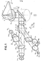
- FIG. 1 illustrates an exemplary embodiment of an optical recording-reading device of the type described above and using laser sources of different wavelengths to produce the radiant energy.
- These lasers La l and La Z emit polarized beams rendered parallel by means of collimating lenses L 1 and L Z.
- the parallel and polarized beam F I illuminates the entrance pupil of a microscope type objective O b .
- a galvanometric mirror M deflects the rays propagating parallel to the optical axis ⁇ x , along the axis ⁇ z .
- the axes ⁇ x and ⁇ z are respectively parallel to the axes X and Y of the reference triede XYZ.
- the objective O b focuses the beam F 1 into a reading spot 3 on the information carrier disk 5. This disk is driven in a rotation movement symbolized by the arrow 6.
- the objective O b and the mirror M are integral with a box 2 constituting the recording-reading head.
- the objective can move along the axis ⁇ z , driven by servo means so that the reading beam is focused exactly on the tracks 7 carrying the information to be read.
- the mirror M is movable around the axis ⁇ y , to ensure a radial displacement of the reading spot.
- a well-known method for recording information consists in forming microreliefs or more generally any modification of an optically readable characteristic. At the surface of the disc 5, these alterations have a variable length depending on the direction of the tracks 7. These tracks are in the form of a single spiral or of concentric circles. The variable length of the alterations is representative of a rectangular carrier wave modulated in duration by the information to be recorded.
- the reading is carried out by reflection of the reading beam focused at 3 on a reflecting surface, for example a metallic deposit carried out on the face of the disc carrying the amplitude or phase alterations.
- the reading beam is modulated by these alterations, this modulation representing the information recorded. on the read side of the disc.
- This modulated reading beam is then detected by photodetector means DA, D B.
- the radiations thus detected are used for several purposes: in addition to their use for the reconstitution of the information read from the disc 5, these radiations are also used to ensure the vertical control and the radial control.
- a recording beam F having been previously modulated in a conventional manner is used by a modulator M which receives the signals to be recorded.
- the recording beam F e is slightly inclined with respect to the reading beam F 1 at the input of the objective OB.
- the two beams, respectively of recording F e and of reading F 1 must be focused on the disc 5 in very close places, so that the spots of recording 4 and of reading 3, are practically merged to stay in the field. of the recording-playback objective O b and so that playback takes place immediately after recording.
- the device according to the invention comprises two beams: a recording beam F e and a reading beam F 1 .
- These two beams are slightly inclined relative to each other at the level of the entrance pupil of the objective.
- a first laser semiconductor La l emitting radiation of wavelength ⁇ 1 and associated with a collimator optic symbolized by the lens L 1 and a second semiconductor laser La Z emitting radiation of wavelength ⁇ 2 and associated with a collimator optic L 2 .
- These two lasers respectively emit the reading beams Flet recording F e .
- These two beams are linearly polarized and their directions of polarization are parallel to each other.
- the two laser sources thus formed emit in directions substantially parallel to the axes ⁇ x and ⁇ 1 , parallel to the axes X and Y of a reference trihedron XYZ.
- the X axis is for example oriented along a radius of an information medium in the form of a disc.
- the optical element 10 which in the case of FIG. 1 is a dichroic mirror.
- the two beams have two different wavelengths: the beam F 1 a wavelength ⁇ 1 and the beam F a wavelength ⁇ 2 .
- This mirror 10 therefore makes it possible to transmit the beam F 1 of wavelength ⁇ 1 and to reflect the beam F e of wavelength ⁇ 2 in order to obtain a composite beam at its output. It also makes it possible to adjust the angle of inclination between the writing and reading beams at the outlet of this mirror by rotating it around the axis ⁇ R. In FIG. 1, this angular difference has not been shown, because it is very small.
- This composite beam then passes through a polarization separator cube 20 consisting of two bonded prisms 27 and 22.
- the separation surface 23 formed by the hypotenuse of these two prisms is treated so as to be polarization separator.
- This element has a preferential optical axis. Incident rays having a direction of polarization parallel to this axis are transmitted in full without modification, parallel to the direction of incidence. Incident rays having a direction of polarization orthogonal to the previous direction are completely reflected in a direction orthogonal to the direction of incidence.
- the faces of the cube have also undergone a surface treatment to avoid stray reflections.
- This cube 20 is oriented to fully transmit this composite beam of determined polarization.
- this plate 21 having been studied to be effective at the two wavelengths considered ⁇ 1 and ⁇ 2 .
- n o n e are the ordinary and extraordinary indices blade ce.tte.
- an achromatic plate such as for example the Fresnel rhombohedron.
- the purpose of the quarter-wave plate 21 is to transform the linear polarizations of the two components of the composite beam into a circular polarization, for example in the levogyre direction.
- the optical axis of the blade must make an angle of ⁇ r / 4 radians with the direction of polarization of the composite beam.
- the composite beam emerging from the quarter-wave plate 21 then reaches the recording-reading head 2 which alone is movable relative to the tracks carrying the information 7.
- the two components of the composite beam are reflected by a galvanometric mirror M, towards the objective O b to be focused on the face of the disc carrying the information tracks 7, in two spots of reading 3 and recording 4 respectively.
- the two components of the composite beam follow the opposite optical path and are always circularly polarized, but in the dextrorotatory direction.
- the composite beam transmitted from the polarizing cube 20 is again linearly polarized. But the new direction of polarization, common to the two components of the composite beam after reflection on the disc, is orthogonal to that of the original beam. It follows that when crossing the cube 20 the two components of the composite beam will be reflected by the face common to the two prisms of this cube, this along the axis ⁇ 2 , orthogonal to the axis ⁇ x to form the composite beam F d .
- This beam Fd is then split into its two components by a second dichroic mirror 11 along the two axes ⁇ 2 and ⁇ 3 .
- Two focusing optics L 3 and L 4 then focus the two components of this composite beam F d to reach respective the photodetector means D A and D B.
- the advantage of the device of the invention is that a maximum optical efficiency is obtained since there are no losses during the mixing or during the separation of the different light beams.
- These photodetector members D A and D B can each comprise, for example, four photodetectors arranged in four quadrants as shown in FIG. 2. These photodetectors are arranged perpendicular to the axes ⁇ 2 and ⁇ 3 .
- the lenses L 3 and L 4 focus on the plane of these photodetectors D A and DB the two components of the composite beam reflected in two separate beams for reading and recording respectively.
- these detection means DA and D B must make it possible to detect focusing errors (the focusing point (3 or 4) is not exactly in the plane of the disc) expressed as an offset in z, and the radial tracking errors (the focal point (3 or 4) is not located on the engraved track, in the case of reading; or on the track that l '' we wish to trace generally materialized in the form of a pre-etched track in the case of recording), expressed in the form of an offset along the radial axis of the disc 5.
- these photodetector means DA are a function of the surface condition of the disc 5 at the point of convergence 3.
- FIG. 2 An embodiment of these photodetectors D A is shown in FIG. 2. It makes it possible to obtain a radial tracking error signal, a focusing error signal, and possibly a read signal.
- the detection means comprise 4 photodetectors 50, 51, 52, 53 arranged in a plane perpendicular to the axis ⁇ 2 . It would be the same for the detection means D B perpendicular to the axis ⁇ 3 .
- the four photodetectors are arranged in a square around the axis ⁇ 2 on as close as possible to each other, and in such a way that in the absence of any focusing error, the power of the beam FA is distributed equally in the four photodetectors, and that, with or without errors, the spot formed in the plane of the photodetectors by the beam F A is entirely contained in their area, so that they detect almost all of the power of the beam F A.
- the sum of the respective output signals of these four photodetectors s 1 , s 2 , s 3 , s 4 indicates the presence or not of an imprint on the disk at the location of the spot and therefore constitutes a read signal.
- the beam F A is a stigmatic beam which therefore converges at a point A.
- the spot obtained in the plane of the photodetectors is circular and centered on the axis ⁇ 2 . It is the same with the beam F B which converges at a point B.
- the reading beam F 1 It would be the same with the writing beam F.
- the radiation diagram of a stigmatic laser is not isotropic so there is an anamorphic prism at the output of this laser to modify the shape of the beam and make it circular.
- Another type of focusing servo consists in using laser sources La I and La 2 astigmatic semiconductor, of the "gain guidance" type, which no longer require the presence of an anamorphic prism. It is then possible to use two laser sources of the same type and to interpose between the separating means 20 and the optical head 2 an astigmatic lens which makes it possible to make the incident composite beam stigmatic. By the same token, it makes the reflected reflected beam astigmatic. Indeed, the incident beam is corrected by this astigmatic lens. The beam focused by the objective O b is therefore devoid of astigmatism. But after thinking about disc 5 it crosses back this astigmatic lens.
- the photodetectors When, after adjusting the position of the photodetectors, there is poor focusing of the beam F on the disk 4, the photodetectors no longer detect a light spot of shape 55 but of shape 56 or shape 57; which allows to extract an error signal.
- the four photodetectors are oriented so that their diagonals overlap with the two axes of Figure 7, Ox and Oy. This amounts to tilting 45 ° the axes limiting the four quadrants of these photodetectors relative to the focus lines which are parallel to the sides of the emitting window of the laser source.
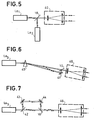
- the two bodies D A and D B each comprise respectively two photodetectors D 1 , D 2 and D 3 , D 4 arranged perpendicular respectively to the axes ⁇ 2 and ⁇ 3 .
- the lenses L 3 and L 4 focus the two components of the composite beam reflected in two read and write spots on the planes of these photodetectors.
- the output signals of the photodetectors D I and D 2 are transmitted to the inputs of two differential amplifiers A 1 , A 2 , the first effecting the sum of the output signals of the photodetectors D 1 and D 2 , and the second difference of these same signals.
- the signals present on the output of amplifier A 1 can be used to generate signals representing the information read from the disc and the signals present on the output of amplifier A Z to produce signals for vertical control of the head recording-playback 2.
- the outputs of the photodetectors D 3 and D 4 are connected to a third differential amplifier A 3 carrying out the sum of the signals present on the outputs of these photodetectors.
- the signals present on the output of the differential amplifier A 3 can be used to generate signals representing the signals being recorded and thus control this recording.
- Radial tracking of the track on the disc can be obtained using the recording beam by connecting the outputs of photodetectors D 3 and D 4 to a fourth differential amplifier A 4 , making the difference of the output signals of photodetectors D 3 and D 4 .
- the signals present on the output of this differential amplifier A 4 can be used to generate error signals.
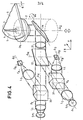
- FIG. 4 A variant of the device according to the invention is shown in Figure 4. Unlike the device illustrated in Figure 1, the separation between the incident beams from the laser sources La 1 and La 2 and the beams reflected by the support 5 is performed at level of each of the reading beams respectively Writing flounder F e .
- the means for separating the beams by polarization 20 have been split (30 and 31) to separate the incident beams from the laser sources La 1 and La 2 respectively from the reflected beams from the disc and directed towards the detector means DA and D B.
- the separation means 30 and 31 are similar to the separator cube 20 of FIG. 1 described above. They make it possible to separate the incident waves having a certain polarization from the waves reflected on the disc which have a polarization of 90 ° thereof. At the output of the dichroic mirror as in the case of FIG. 1, the composite incident beam is obtained having two components respectively for reading and recording directions of parallel polarization.
- the quarter-wave plate 21 is dichroic. But it is also possible to replace this plate 21 by two quarter-wave monochromatic plates, for each of the two wavelengths considered ⁇ 1 and ⁇ 2 . They can then be inserted respectively between the separator cube 30 and the dichroic mirror 10, and between the separator cube 31 and the dichroic mirror 10.
- the laser sources considered so far are semiconductor laser sources. These lasers are characterized by a very divergent emission. They require the use of collimator optics L 1 and L 2 .
- these laser sources La 1 and La 2 can also be gas lasers, for example HeNe gas lasers. These lasers emit a polarized parallel beam. As is known, the section of this beam is very small and must therefore be enlarged. Also the lenses L 1 and L 2 must be replaced by afocals such that the parallel emerging beams can then make it possible to cover the entrance pupil of the objective O b . In the case of Figure 1, we can consider only an afocal arranged as shown in Figure 5.
Landscapes
- Physics & Mathematics (AREA)
- Optics & Photonics (AREA)
- Optical Head (AREA)
Applications Claiming Priority (2)
| Application Number | Priority Date | Filing Date | Title |
|---|---|---|---|
| FR8101288 | 1981-01-23 | ||
| FR8101288A FR2498752B1 (fr) | 1981-01-23 | 1981-01-23 | Dispositif optique d'enregistrement lecture d'un support d'information comportant deux sources laser de longueurs d'ondes differentes |
Publications (1)
| Publication Number | Publication Date |
|---|---|
| EP0056920A1 true EP0056920A1 (de) | 1982-08-04 |
Family
ID=9254454
Family Applications (1)
| Application Number | Title | Priority Date | Filing Date |
|---|---|---|---|
| EP81402053A Withdrawn EP0056920A1 (de) | 1981-01-23 | 1981-12-22 | Optische Einrichtung zur Aufzeichnung und Wiedergabe von einem Informationsträger mit zwei Laserquellen verschiedener Wellenlängen |
Country Status (3)
| Country | Link |
|---|---|
| EP (1) | EP0056920A1 (de) |
| JP (1) | JPS57141031A (de) |
| FR (1) | FR2498752B1 (de) |
Cited By (8)
| Publication number | Priority date | Publication date | Assignee | Title |
|---|---|---|---|---|
| EP0082716A1 (de) * | 1981-12-21 | 1983-06-29 | BURROUGHS CORPORATION (a Michigan corporation) | Verfahren zum Vorformatieren einer optischen Scheibe |
| EP0083193A1 (de) * | 1981-12-21 | 1983-07-06 | BURROUGHS CORPORATION (a Michigan corporation) | Vorrichtung zum Vorformatieren einer optischen Scheibe |
| EP0127448A1 (de) * | 1983-05-31 | 1984-12-05 | Sony Corporation | Gerät zur Fokusfehlerdetektion |
| GB2158962A (en) * | 1984-04-25 | 1985-11-20 | Fuji Photo Film Co Ltd | Combining and separating polarised light beams |
| EP0159785A3 (en) * | 1984-03-07 | 1986-03-05 | Kabushiki Kaisha Toshiba | Optical recording & reproducing apparatus |
| EP0099123A3 (en) * | 1982-07-15 | 1986-08-20 | Matsushita Electric Industrial Co., Ltd. | Optical recording and reproducing head |
| EP0246899A1 (de) * | 1986-05-21 | 1987-11-25 | Canon Kabushiki Kaisha | Gerät zur optischen Aufzeichnung und Wiedergabe von Informationen |
| EP0494767A3 (en) * | 1991-01-09 | 1993-03-03 | Sony Corporation | Optical pick-up devices for recordable discs |
Families Citing this family (4)
| Publication number | Priority date | Publication date | Assignee | Title |
|---|---|---|---|---|
| NL8101932A (nl) * | 1981-04-21 | 1982-11-16 | Philips Nv | Inrichting voor het inschrijven en uitlezen van informatiesporen in een optische registratiedrager. |
| JPS60234246A (ja) * | 1984-05-04 | 1985-11-20 | Matsushita Electric Ind Co Ltd | 光学ヘツド |
| JPS62109242A (ja) * | 1985-11-07 | 1987-05-20 | Omron Tateisi Electronics Co | ダブルビ−ム光ヘツド |
| JPS6370936A (ja) * | 1986-09-11 | 1988-03-31 | Asahi Optical Co Ltd | 追記型光学式情報記録再生装置 |
Citations (5)
| Publication number | Priority date | Publication date | Assignee | Title |
|---|---|---|---|---|
| FR2313731A1 (fr) * | 1975-06-06 | 1976-12-31 | Hitachi Ltd | Appareil de reproduction d'informations |
| DE2634243A1 (de) * | 1976-07-30 | 1978-02-02 | Bosch Gmbh Robert | System zur aufzeichnung und/oder wiedergabe von signalen mittels strahlen |
| JPS5476108A (en) * | 1977-11-29 | 1979-06-18 | Canon Inc | Optical device |
| US4174150A (en) * | 1976-02-23 | 1979-11-13 | Jersey Nuclear-Avco Isotopes, Inc. | System for combining laser beams of diverse frequencies |
| FR2440055A1 (fr) * | 1978-10-24 | 1980-05-23 | Mitsubishi Electric Corp | Systeme optique d'enregistrement et de reproduction de signaux |
Family Cites Families (2)
| Publication number | Priority date | Publication date | Assignee | Title |
|---|---|---|---|---|
| JPS5110879A (ja) * | 1974-07-17 | 1976-01-28 | Kureha Chemical Ind Co Ltd | Haipurasuchitsukuoryoshita rejinkonkuriitono seizohoho |
| IL50516A (en) * | 1976-02-23 | 1978-09-29 | Jersey Nuclear Avco Isotopes | System for combining laser beams of diverse frequencies |
-
1981
- 1981-01-23 FR FR8101288A patent/FR2498752B1/fr not_active Expired
- 1981-12-22 EP EP81402053A patent/EP0056920A1/de not_active Withdrawn
-
1982
- 1982-01-21 JP JP57008219A patent/JPS57141031A/ja active Pending
Patent Citations (5)
| Publication number | Priority date | Publication date | Assignee | Title |
|---|---|---|---|---|
| FR2313731A1 (fr) * | 1975-06-06 | 1976-12-31 | Hitachi Ltd | Appareil de reproduction d'informations |
| US4174150A (en) * | 1976-02-23 | 1979-11-13 | Jersey Nuclear-Avco Isotopes, Inc. | System for combining laser beams of diverse frequencies |
| DE2634243A1 (de) * | 1976-07-30 | 1978-02-02 | Bosch Gmbh Robert | System zur aufzeichnung und/oder wiedergabe von signalen mittels strahlen |
| JPS5476108A (en) * | 1977-11-29 | 1979-06-18 | Canon Inc | Optical device |
| FR2440055A1 (fr) * | 1978-10-24 | 1980-05-23 | Mitsubishi Electric Corp | Systeme optique d'enregistrement et de reproduction de signaux |
Non-Patent Citations (1)
| Title |
|---|
| PATENTS ABSTRACTS OF JAPAN, vol. 3, no. 98, 18 août 1979, page 97 E 131 & JP-A-54 076108 (CANON K.K.) (18-06-1979) * |
Cited By (10)
| Publication number | Priority date | Publication date | Assignee | Title |
|---|---|---|---|---|
| EP0082716A1 (de) * | 1981-12-21 | 1983-06-29 | BURROUGHS CORPORATION (a Michigan corporation) | Verfahren zum Vorformatieren einer optischen Scheibe |
| EP0083193A1 (de) * | 1981-12-21 | 1983-07-06 | BURROUGHS CORPORATION (a Michigan corporation) | Vorrichtung zum Vorformatieren einer optischen Scheibe |
| EP0099123A3 (en) * | 1982-07-15 | 1986-08-20 | Matsushita Electric Industrial Co., Ltd. | Optical recording and reproducing head |
| EP0127448A1 (de) * | 1983-05-31 | 1984-12-05 | Sony Corporation | Gerät zur Fokusfehlerdetektion |
| EP0159785A3 (en) * | 1984-03-07 | 1986-03-05 | Kabushiki Kaisha Toshiba | Optical recording & reproducing apparatus |
| GB2158962A (en) * | 1984-04-25 | 1985-11-20 | Fuji Photo Film Co Ltd | Combining and separating polarised light beams |
| EP0246899A1 (de) * | 1986-05-21 | 1987-11-25 | Canon Kabushiki Kaisha | Gerät zur optischen Aufzeichnung und Wiedergabe von Informationen |
| US5163034A (en) * | 1986-05-21 | 1992-11-10 | Canon Kabushiki Kaisha | Tracking device to effect tracking pull-in in an optical recording and reproducing apparatus by vibrating a light spot |
| EP0494767A3 (en) * | 1991-01-09 | 1993-03-03 | Sony Corporation | Optical pick-up devices for recordable discs |
| US5260927A (en) * | 1991-01-09 | 1993-11-09 | Sony Corporation | Optical pickup device for recordable disc and dichroic mirror |
Also Published As
| Publication number | Publication date |
|---|---|
| FR2498752A1 (fr) | 1982-07-30 |
| JPS57141031A (en) | 1982-09-01 |
| FR2498752B1 (fr) | 1985-07-05 |
Similar Documents
| Publication | Publication Date | Title |
|---|---|---|
| EP0040995B1 (de) | Optische Aufnahme-Wiedergabe-Vorrichtung für einen Informationsträger | |
| EP0088671B1 (de) | Optischer Kopf in einer Schreib-Lese-Einrichtung für einen Informationsträger | |
| EP0029755B1 (de) | Stigmatische optische Emitter/Empfänger-Vorrichtung für kohärente Strahlung und optischer Schreib/Lesekopf mit einer solchen Vorrichtung | |
| EP0033052B1 (de) | Optische Vorrichtung zur Aufnahme-Wiedergabe von Informationsträgern und optisches Speichersystem mit einer solchen Vorrichtung | |
| FR2504300A1 (fr) | Dispositif d'enregistrement et de lecture d'information dans des pistes d'information d'un porteur d'enregistrement optique | |
| EP0023868B1 (de) | Optische Vorrichtung zum Spurzugriff eines Informationsträgers und optisches Speichersystem mit einer solchen Vorrichtung | |
| FR2601174A1 (fr) | Dispositif formant tete de type optique, notamment pour l'enregistrement et la lecture de donnees. | |
| FR2566953A1 (fr) | Dispositif de tete optique | |
| FR2613866A1 (fr) | Appareil d'enregistrement et de reproduction optique d'information | |
| FR2498340A1 (fr) | Procede et appareil de detection d'un signal d'erreur de focalisation d'un objectif | |
| FR2498752A1 (fr) | Dispositif optique d'enregistrement lecture d'un support d'information comportant deux sources laser de longueurs d'ondes differentes | |
| EP0022682B1 (de) | Optischer Lesekopf mit Halbleiter-Laserquelle und eine mit optischer Reflexion arbeitende Lesevorrichtung zum Lesen eines Informationsträgers, die einen solchen optischen Lesekopf enthält | |
| FR2649239A1 (fr) | Systeme de detection d'erreur de focalisation pour tete optique | |
| EP0077693B1 (de) | Opto-elektronische Vorrichtung zum Auslesen der Information eines magnetischen Aufzeichnungsträgers | |
| FR2524158A1 (fr) | Dispositif de correction de l'astigmatisme d'un appareil optique utilisant comme source de lumiere un laser semi-conducteur | |
| WO1990013117A1 (fr) | Dispositif de lecture optique pour support d'enregistrement optique | |
| US6104688A (en) | Objective lens, reproducing apparatus and reproducing method | |
| FR2664394A1 (fr) | Systeme optique utilisant une lumiere polarisee. | |
| EP0057339B1 (de) | Optischer Fokussierungsfehlerdetektor und damit ausgerüsteter optischer Aufnehmer-Leser | |
| EP0889466B1 (de) | Optisches Aufzeichnungsmedium mit zwei übereinander angeordneten Schichten, Aufzeichnungsgerät und Leseverfahren dafür | |
| FR2489574A1 (fr) | Systeme opto-electronique de detection de mise au point et de reglage exact de piste | |
| FR2710443A1 (fr) | Procédé d'enregistrement d'informations sur un disque optique et de lecture de celles-ci, support d'enregistrement et agencement de lecture pour la mise en Óoeuvre du procédé. | |
| EP0453343B1 (de) | Verfahren zur Herstellung von verschobenen pits auf einem vorgeprägten Informationsmedium, Verfahren zur Ausverarbeitung eines Spurfehlersignals und Wiedergabegerät zur Realisierung dieses Verfahrens | |
| FR2504301A1 (fr) | Support d'informations mobile et dispositif d'enregistrement-lecture comprenant un tel support | |
| JPH0743833B2 (ja) | 光学式記録再生装置 |
Legal Events
| Date | Code | Title | Description |
|---|---|---|---|
| PUAI | Public reference made under article 153(3) epc to a published international application that has entered the european phase |
Free format text: ORIGINAL CODE: 0009012 |
|
| AK | Designated contracting states |
Designated state(s): DE GB IT NL |
|
| 17P | Request for examination filed |
Effective date: 19820812 |
|
| STAA | Information on the status of an ep patent application or granted ep patent |
Free format text: STATUS: THE APPLICATION IS DEEMED TO BE WITHDRAWN |
|
| 18D | Application deemed to be withdrawn |
Effective date: 19840703 |
|
| RIN1 | Information on inventor provided before grant (corrected) |
Inventor name: LE MERER, JEAN-PIERRE Inventor name: LETERME, DOMINIQUE |