EP0056923B1 - Antenna having small dimensions - Google Patents
Antenna having small dimensions Download PDFInfo
- Publication number
- EP0056923B1 EP0056923B1 EP81402082A EP81402082A EP0056923B1 EP 0056923 B1 EP0056923 B1 EP 0056923B1 EP 81402082 A EP81402082 A EP 81402082A EP 81402082 A EP81402082 A EP 81402082A EP 0056923 B1 EP0056923 B1 EP 0056923B1
- Authority
- EP
- European Patent Office
- Prior art keywords
- metal
- receiver
- metal plate
- box
- antenna
- Prior art date
- Legal status (The legal status is an assumption and is not a legal conclusion. Google has not performed a legal analysis and makes no representation as to the accuracy of the status listed.)
- Expired
Links
- 239000002184 metal Substances 0.000 claims description 40
- 230000005684 electric field Effects 0.000 claims description 7
- 238000004804 winding Methods 0.000 description 3
- 230000006978 adaptation Effects 0.000 description 2
- 239000003990 capacitor Substances 0.000 description 2
- 230000008878 coupling Effects 0.000 description 2
- 238000010168 coupling process Methods 0.000 description 2
- 238000005859 coupling reaction Methods 0.000 description 2
- 238000010586 diagram Methods 0.000 description 2
- 240000008042 Zea mays Species 0.000 description 1
- 230000000694 effects Effects 0.000 description 1
- 239000012212 insulator Substances 0.000 description 1
- 238000001465 metallisation Methods 0.000 description 1
- 238000004377 microelectronic Methods 0.000 description 1
- 238000000926 separation method Methods 0.000 description 1
Images

Classifications
-
- H—ELECTRICITY
- H01—ELECTRIC ELEMENTS
- H01Q—ANTENNAS, i.e. RADIO AERIALS
- H01Q1/00—Details of, or arrangements associated with, antennas
- H01Q1/12—Supports; Mounting means
- H01Q1/22—Supports; Mounting means by structural association with other equipment or articles
- H01Q1/24—Supports; Mounting means by structural association with other equipment or articles with receiving set
- H01Q1/241—Supports; Mounting means by structural association with other equipment or articles with receiving set used in mobile communications, e.g. GSM
- H01Q1/242—Supports; Mounting means by structural association with other equipment or articles with receiving set used in mobile communications, e.g. GSM specially adapted for hand-held use
- H01Q1/243—Supports; Mounting means by structural association with other equipment or articles with receiving set used in mobile communications, e.g. GSM specially adapted for hand-held use with built-in antennas
-
- H—ELECTRICITY
- H01—ELECTRIC ELEMENTS
- H01Q—ANTENNAS, i.e. RADIO AERIALS
- H01Q1/00—Details of, or arrangements associated with, antennas
- H01Q1/27—Adaptation for use in or on movable bodies
- H01Q1/273—Adaptation for carrying or wearing by persons or animals
-
- H—ELECTRICITY
- H01—ELECTRIC ELEMENTS
- H01Q—ANTENNAS, i.e. RADIO AERIALS
- H01Q9/00—Electrically-short antennas having dimensions not more than twice the operating wavelength and consisting of conductive active radiating elements
- H01Q9/04—Resonant antennas
- H01Q9/30—Resonant antennas with feed to end of elongated active element, e.g. unipole
- H01Q9/40—Element having extended radiating surface
Definitions
- the present invention relates to an antenna, and more particularly a small antenna intended to equip a portable receiver.
- small antenna is understood to mean an antenna whose dimension is much less than the wavelength of the waves received.
- the antenna is traditionally made up of two metal plates, forming an electrical dipole, between which the receiver is interposed, an adaptation circuit generally constituted by an inductor, being provided between the receiver and each of the metal plates constituting the dipole.
- the poles of the dipole forming the antenna consist of two housings separated by an insulator, the coupling of the dipole to the circuits of the radio station being carried out using a transformer.
- the device described however has the drawbacks of remaining bulky and of requiring a conductive screen to protect the radio receiver against the effects varying the capacitance produced by mobile objects near the receiver.
- the present invention aims to overcome the aforementioned drawbacks.
- the subject of the invention is a small antenna forming an electrical dipole and intended to equip a portable radio receiver, characterized in that the first pole of the electrical dipole is constituted by a metal box in which are housed the the set of components of the radio receiver and which forms a zero electric field reference potential plane for the receiver, the second pole of the electric dipole is formed by a metal plate connected to the components of the radio receiver, the metal plate being fixed spaced apart and facing a face of the metal box so that the space between the metal plate and the facing face of the metal box has a value much less than the reception wavelength of the radio receiver, the dipole formed by the metal box and the metal plate being such that the plane of the reference potential of the first pole is located at half the distance separating the face of the box directly in look of the metal plate from that of the case opposite it.
- An inductor 4 intended to ensure the adaptation of the antenna of the receiver, is provided with a first terminal connected to the plate 1 and a second terminal connected to a first input of an amplifier (not shown in the figure 1) located inside the metal housing and forming part of the input stage of the receiver, a second input of this amplifier being connected to the housing.
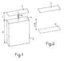
- the antenna thus constituted behaves like an electric dipole comprising, as shown in FIG. 2, a first metal plate constituted by plate 1 and a second metal plate constituted by a virtual metal plate 5 located at mid -height (2) of the housing 2.
- FIG. 3 representing the equipotential lines obtained around the antenna according to the invention when the latter is placed in a uniform electric field, in a rheographic tank.
- aa ' shows that the electric field which bypasses the housing from below is not used.
- the electric field is zero towards the middle of the box (points 0 and 0 ').
- the tangential component of the electric field is zero at the limit of the box.
- the structure of this antenna has several advantages over the structure of the antenna traditionally used.
- a first advantage is that the size is reduced. More precisely, the height of the antenna and housing assembly is reduced by a height equal to L.
- a second advantage is that we save inductances. In fact, before, the signals supplied by the two metal plates were in phase opposition. It was therefore necessary to provide a mid-point transformer consisting of a first winding provided with a first terminal connected to the first plate, a second terminal connected to the second plate, and a second winding provided with a first terminal connected to the input of an amplifier forming part of the input stage of the receiver and of a second terminal set to a reference potential, the midpoint of the first winding being also set to this reference potential.
- the second antenna plate according to the invention consists of the receiver housing. It therefore suffices to connect the first terminal of the amplifier to the plate 1 via the inductor 4, and a second terminal of the amplifier to the housing 2 which by definition constitutes a reference potential.
- a third advantage is that the metallization of the receiver housing provides impermeability to stray electric fields. The electronic circuits constituting the receiver are thus protected from direct coupling with the external environment.
Landscapes
- Engineering & Computer Science (AREA)
- Computer Networks & Wireless Communication (AREA)
- Details Of Aerials (AREA)
- Support Of Aerials (AREA)
Description
La présente invention concerne une antenne, et plus particulièrement une antenne de petite dimension destinée à équiper un récepteur portatif.The present invention relates to an antenna, and more particularly a small antenna intended to equip a portable receiver.
On entend par antenne de petite dimension une antenne dont la dimension est très inférieure à la longueur d'onde des ondes reçues.The term “small antenna” is understood to mean an antenna whose dimension is much less than the wavelength of the waves received.
Ce type de récepteur se rencontre notamment dans les systèmes de transmission de signaux radioélectriques émis par un émetteur de base et destinés à des usagers, munis de récepteurs portatifs, se déplaçant à l'intérieur d'un périmètre défini par un rayon de grandeur limitée autour de leur poste téléphonique ou radiotéléphonique d'abonné. Ces systèmes sont plus connus sous le terme de systèmes d'appel unilatéral ou encore de systèmes «EUROSIGNAL».This type of receiver is encountered in particular in systems for transmitting radioelectric signals emitted by a basic transmitter and intended for users, provided with portable receivers, moving within a perimeter defined by a radius of magnitude limited around of their subscriber telephone or radiotelephone extension. These systems are better known under the term of unilateral calling systems or “EUROSIGNAL” systems.
Dans ces systèmes, il est souhaitable pour le confort de l'usager, de réduire le plus possible les dimensions du récepteur et de l'antenne incorporée au récepteur.In these systems, it is desirable for the comfort of the user, to reduce as much as possible the dimensions of the receiver and of the antenna incorporated in the receiver.
L'antenne est traditionnellement constituée de deux plaques métalliques, formant un dipôle électrique, entre lesquelles est interposé le récepteur, un circuit d'adaptation généralement constitué par une inductance, étant prévu entre le récepteur et chacune des plaques métalliques constituant le dipôle.The antenna is traditionally made up of two metal plates, forming an electrical dipole, between which the receiver is interposed, an adaptation circuit generally constituted by an inductor, being provided between the receiver and each of the metal plates constituting the dipole.
Les efforts de réduction d'encombrement ont jusqu'à présent été essentiellement orientés vers la réduction du volume occupé par le récepteur, et ont bénéficié largement des apports de la microélectronique dans ce domaine.The efforts to reduce congestion have so far been essentially oriented towards reducing the volume occupied by the receiver, and have benefited greatly from the contributions of microelectronics in this field.
En revanche il parait difficilement envisageable sans changer la structure de l'antenne, de réduire le volume occupé par la structure décrite précédemment.On the other hand, it seems difficult to envisage without changing the structure of the antenna, to reduce the volume occupied by the structure described above.
Un exemple de réalisation allant dans ce sens est cependant décrit dans le brevet français 1175 744. Dans cet exemple les pôles du dipôle formant l'antenne sont constitués par deux boîtiers séparés par un isolant, le couplage du dipôle aux circuits du poste radio étant réalisé à l'aide d'un transformateur. Le dispositif décrit a toutefois pour inconvénients de rester encombrant et de nécessiter un écran conducteur pour protéger le récepteur radio contre les effets faisant varier la capacitance produits par des objets mobiles à proximité du récepteur.An exemplary embodiment going in this direction is however described in the French patent 1175 744. In this example the poles of the dipole forming the antenna consist of two housings separated by an insulator, the coupling of the dipole to the circuits of the radio station being carried out using a transformer. The device described however has the drawbacks of remaining bulky and of requiring a conductive screen to protect the radio receiver against the effects varying the capacitance produced by mobile objects near the receiver.
La présente invention a pour but de pallier les inconvénients précités.The present invention aims to overcome the aforementioned drawbacks.
A cet effet, l'invention a pour objet, une antenne de petite dimension formant un dipôle électrique et destinée à équiper un récepteur radio portatif, caractérisée en ce que le premier pôle du dipôle électrique est constitué par une boîte métallique dans laquelle sont logés l'ensemble des composants du radio récepteur et qui forme un plan de potentiel de référence de champ électrique nul pour le récepteur, le deuxième pôle du dipôle électrique est formé par une plaque métallique connectée aux composants du récepteur radio, la plaque métallique étant fixée espacée et en regard d'une face de la boîte métallique de sorte que l'espace entre la plaque métallique et la face en regard de la boîte métallique a une valeur très inférieure à la longueur d'onde de réception du récepteur radio, le dipôle formé par la boîte métallique et la plaque métallique étant tel que le plan du potentiel de référence du premier pôle est situé à la moitié de la distance séparant la face du boîtier directement en regard de la plaque métallique de celle du boîtier qui lui est opposée.To this end, the subject of the invention is a small antenna forming an electrical dipole and intended to equip a portable radio receiver, characterized in that the first pole of the electrical dipole is constituted by a metal box in which are housed the the set of components of the radio receiver and which forms a zero electric field reference potential plane for the receiver, the second pole of the electric dipole is formed by a metal plate connected to the components of the radio receiver, the metal plate being fixed spaced apart and facing a face of the metal box so that the space between the metal plate and the facing face of the metal box has a value much less than the reception wavelength of the radio receiver, the dipole formed by the metal box and the metal plate being such that the plane of the reference potential of the first pole is located at half the distance separating the face of the box directly in look of the metal plate from that of the case opposite it.
Les objets et caractéristiques de la présente invention apparaîtront plus clairement à la lecture de la description suivante d'un exemple de réalisation, ladite description étant faite en relation avec les dessins ci-annexés dans lesquels:
- - la figure 1 montre la structure d'une antenne conforme à l'invention;
- - la figure 2 est un schéma équivalent de la structure représentée à la figure 1;
- - la figure 3 est un diagramme représentant les lignes équipotentielles obtenues lorsqu'on expérimente l'antenne conforme à l'invention dans une cuve rhéographique.
- L'antenne représentée sur la figure 1 comporte une plaque métallique 1 et un boîtier métallique 2, de hauteur H renfermant les éléments constituant le récepteur (ces éléments n'étant pas représentés sur la figure). A titre d'exemple le boîtier métallique a une forme parallélépipédique, mais une forme quelconque conviendrait. Une
face 3 duparallélépipède 2 est placée en regard de laplaque 1, à une distance L de celle-ci. A titre d'exemple, la face 3 a une surface sensiblement égale à celle de laplaque 1. L'antenne est dite de petite dimension car la dimension L est très inférieure à la longueur d'onde des ondes reçues.
- - Figure 1 shows the structure of an antenna according to the invention;
- - Figure 2 is an equivalent diagram of the structure shown in Figure 1;
- - Figure 3 is a diagram showing the equipotential lines obtained when testing the antenna according to the invention in a rheographic tank.
- The antenna shown in Figure 1 has a
metal plate 1 and ametal housing 2, of height H containing the elements constituting the receiver (these elements are not shown in the figure). By way of example, the metal case has a parallelepiped shape, but any shape would be suitable. Oneface 3 of theparallelepiped 2 is placed opposite theplate 1, at a distance L from the latter. By way of example, theface 3 has a surface substantially equal to that of theplate 1. The antenna is said to be of small dimension because the dimension L is much less than the wavelength of the waves received.
Une inductance 4, destinée à assurer l'adaptation de l'antenne du récepteur, est munie d'une première borne reliée à la plaque 1 et d'une seconde borne reliée à une première entrée d'un amplificateur (non représenté sur la figure 1) situé à l'intérieur du boîtier métallique et faisant partie de l'étage d'entrée du récepteur, une seconde entrée de cet amplificateur étant reliée au boîtier.An
L'expérimentation prouve que l'antenne ainsi constituée se comporte comme un dipôle électrique comportant, comme le montre la figure 2, une première plaque métallique constituée par la plaque 1 et une seconde plaque métallique constituée par une plaque métallique virtuelle 5 se situant à mi-hauteur (2) du boîtier 2.Experimentation proves that the antenna thus constituted behaves like an electric dipole comprising, as shown in FIG. 2, a first metal plate constituted by
Il suffit pour cela de se référer à la figure 3 représentant les lignes équipotentielles obtenues autour de l'antenne conforme à l'invention lorsqu'on place celle-ci dans un champ électrique uniforme, en cuve rhéographique. Sur cette figure on remarque une concentration du champ qui passe entre les armatures du condensateur formé par la plaque métallique et par la face du boîtier métallique qui est placée en regard de la plaque métallique. On remarque également une ligne de séparation aa' qui montre que le champ électrique qui contourne le boîtier par le bas n'est pas utilisé. On remarque également que le champ électrique est nul vers le milieu du boîtier (points 0 et 0'). On remarque également que la composante tangentielle du champ électrique est nulle à la limite du boîtier.For this, it suffices to refer to FIG. 3 representing the equipotential lines obtained around the antenna according to the invention when the latter is placed in a uniform electric field, in a rheographic tank. In this figure, we can see a concentration of the field which passes between the armatures of the capacitor formed by the metal plate and by the face of the metal case which is placed opposite the metal plate. There is also a separation line aa 'which shows that the electric field which bypasses the housing from below is not used. We also note that the electric field is zero towards the middle of the box (points 0 and 0 '). We also note that the tangential component of the electric field is zero at the limit of the box.
On constate donc que tout se passe comme si l'ensemble formé par la plaque métallique et par le boîtier métallique se comportait comme un condensateur dont une première armature est constituée par la plaque métallique, et dont une seconde armature est constituée non pas par la face du boîtier placée en regard de la plaque métallique, mais par une plaque virtuelle située à mi-hauteur du boîtier.It can therefore be seen that everything happens as if the assembly formed by the metal plate and by the metal case behaved like a capacitor, a first frame of which is formed by the metal plate, and a second frame of which is not made up of the face of the box placed opposite the metal plate, but by a virtual plate located halfway up the box.
La structure de cette antenne présente plusieurs avantages par rapport à la structure de l'antenne utilisée traditionnellement.The structure of this antenna has several advantages over the structure of the antenna traditionally used.
Un premier avantage est que l'encombrement se trouve réduit. Plus précisément la hauteur de l'ensemble antenne et boîtier se trouve réduite d'une hauteur égale à L.A first advantage is that the size is reduced. More precisely, the height of the antenna and housing assembly is reduced by a height equal to L.
Un second avantage est qu'on réalise une économie d'inductances. En effet auparavant les signaux fournis par les deux plaques métalliques étaient en opposition de phase. Il était donc nécessaire de prévoir un transformateur à point milieu constitué d'un premier enroulement muni d'une première borne reliée à la première plaque, d'une seconde borne reliée à la seconde plaque, et d'un second enroulement muni d'une première borne reliée à l'entrée d'un amplificateur faisant partie de l'étage d'entrée du récepteur et d'une seconde borne mise à un potentiel de référence, le point milieu du premier enroulement étant également mis à ce potentiel de référence. Or la seconde plaque de l'antenne conforme à l'invention est constituée par le boîtier du récepteur. Il suffit donc de relier la première borne de l'amplificateur à la plaque 1 via l'inductance 4, et une seconde borne de l'amplificateur au boîtier 2 qui constitue par définition un potentiel de référence. Un troisième avantage est que la métallisation du boîtier du récepteur procure une impermébilité aux champs électriques parasites. Les circuits électroniques constituant le récepteur se trouvent ainsi protégés des couplages directs avec l'environnement extérieur.A second advantage is that we save inductances. In fact, before, the signals supplied by the two metal plates were in phase opposition. It was therefore necessary to provide a mid-point transformer consisting of a first winding provided with a first terminal connected to the first plate, a second terminal connected to the second plate, and a second winding provided with a first terminal connected to the input of an amplifier forming part of the input stage of the receiver and of a second terminal set to a reference potential, the midpoint of the first winding being also set to this reference potential. However, the second antenna plate according to the invention consists of the receiver housing. It therefore suffices to connect the first terminal of the amplifier to the
Claims (6)
Applications Claiming Priority (2)
| Application Number | Priority Date | Filing Date | Title |
|---|---|---|---|
| FR8101291 | 1981-01-23 | ||
| FR8101291A FR2498819B1 (en) | 1981-01-23 | 1981-01-23 | SMALL ANTENNA |
Publications (3)
| Publication Number | Publication Date |
|---|---|
| EP0056923A2 EP0056923A2 (en) | 1982-08-04 |
| EP0056923A3 EP0056923A3 (en) | 1982-08-11 |
| EP0056923B1 true EP0056923B1 (en) | 1986-10-08 |
Family
ID=9254457
Family Applications (1)
| Application Number | Title | Priority Date | Filing Date |
|---|---|---|---|
| EP81402082A Expired EP0056923B1 (en) | 1981-01-23 | 1981-12-28 | Antenna having small dimensions |
Country Status (5)
| Country | Link |
|---|---|
| US (1) | US4491843A (en) |
| EP (1) | EP0056923B1 (en) |
| DE (1) | DE3175454D1 (en) |
| DK (1) | DK21382A (en) |
| FR (1) | FR2498819B1 (en) |
Families Citing this family (36)
| Publication number | Priority date | Publication date | Assignee | Title |
|---|---|---|---|---|
| DE3214449A1 (en) * | 1982-04-20 | 1983-10-27 | Standard Elektrik Lorenz Ag, 7000 Stuttgart | MINIATURIZED RADIO RECEIVER |
| DE3302876A1 (en) * | 1983-01-28 | 1984-08-02 | Robert Bosch Gmbh, 7000 Stuttgart | DIPOLANTENNA FOR PORTABLE RADIO DEVICES |
| US6822553B1 (en) | 1985-10-16 | 2004-11-23 | Ge Interlogix, Inc. | Secure entry system with radio reprogramming |
| US5475375A (en) * | 1985-10-16 | 1995-12-12 | Supra Products, Inc. | Electronic access control systems |
| US6072402A (en) * | 1992-01-09 | 2000-06-06 | Slc Technologies, Inc. | Secure entry system with radio communications |
| US4740794A (en) * | 1986-01-03 | 1988-04-26 | Motorola, Inc. | Connectorless antenna coupler |
| US4831661A (en) * | 1986-10-09 | 1989-05-16 | Toko Kabushiki Kaisha | RF tuning circuit |
| US4790030A (en) * | 1986-11-25 | 1988-12-06 | Rca Licensing Corporation | Tuner with insertable antenna coupler |
| US4876552A (en) * | 1988-04-27 | 1989-10-24 | Motorola, Inc. | Internally mounted broadband antenna |
| FI81927C (en) * | 1988-10-26 | 1990-12-10 | Nokia Mobira Oy | ANTENN FOER RADIO TELEPHONE. |
| GB2237449B (en) * | 1989-09-30 | 1994-03-30 | Hi Trak Systems Ltd | Transmitter and antenna |
| DE4113277C2 (en) * | 1991-04-19 | 1996-08-08 | Hagenuk Telecom Gmbh | Antenna for a mobile phone |
| JP3251680B2 (en) * | 1991-12-26 | 2002-01-28 | 株式会社東芝 | Portable radio |
| AU673983B2 (en) * | 1992-01-09 | 1996-12-05 | Ge Security, Inc. | Secure entry system with radio communication |
| TW320813B (en) * | 1996-04-05 | 1997-11-21 | Omron Tateisi Electronics Co | |
| JP3838815B2 (en) * | 1999-05-10 | 2006-10-25 | 日本電気株式会社 | Mobile phone |
| WO2000076023A1 (en) * | 1999-06-02 | 2000-12-14 | University Of Waterloo | Flat-plate monopole antennae |
| US6281851B1 (en) | 2000-01-21 | 2001-08-28 | Motorola, Inc. | Antenna assembly and communication device utilizing such antenna assembly |
| US6266019B1 (en) * | 2000-07-21 | 2001-07-24 | Ericsson Inc. | System for increasing antenna efficiency |
| GB0019335D0 (en) * | 2000-08-08 | 2000-09-27 | Koninkl Philips Electronics Nv | Wireless terminal |
| WO2002013306A1 (en) * | 2000-08-08 | 2002-02-14 | Koninklijke Philips Electronics N.V. | Wireless terminal |
| SE522492C2 (en) * | 2000-10-27 | 2004-02-10 | Ericsson Telefon Ab L M | Antenna device for a mobile terminal |
| US6660948B2 (en) | 2001-02-28 | 2003-12-09 | Vip Investments Ltd. | Switch matrix |
| ATE255283T1 (en) * | 2001-04-19 | 2003-12-15 | Ericsson Telefon Ab L M | END-FEEDED ANTENNA FOR MOBILE DEVICE |
| WO2002087010A2 (en) * | 2001-04-19 | 2002-10-31 | Telefonaktiebolaget L M Ericsson (Publ) | End-fed antenna for a mobile terminal |
| GB0112265D0 (en) | 2001-05-19 | 2001-07-11 | Koninkl Philips Electronics Nv | Antenna arrangement |
| US7755506B1 (en) | 2003-09-03 | 2010-07-13 | Legrand Home Systems, Inc. | Automation and theater control system |
| US7307542B1 (en) | 2003-09-03 | 2007-12-11 | Vantage Controls, Inc. | System and method for commissioning addressable lighting systems |
| US7394451B1 (en) | 2003-09-03 | 2008-07-01 | Vantage Controls, Inc. | Backlit display with motion sensor |
| US7778262B2 (en) * | 2005-09-07 | 2010-08-17 | Vantage Controls, Inc. | Radio frequency multiple protocol bridge |
| US8203492B2 (en) | 2008-08-04 | 2012-06-19 | Fractus, S.A. | Antennaless wireless device |
| WO2010015364A2 (en) | 2008-08-04 | 2010-02-11 | Fractus, S.A. | Antennaless wireless device capable of operation in multiple frequency regions |
| WO2011095330A1 (en) | 2010-02-02 | 2011-08-11 | Fractus, S.A. | Antennaless wireless device comprising one or more bodies |
| CN103155276B (en) | 2010-08-03 | 2015-11-25 | 弗拉克托斯天线股份有限公司 | Wireless device capable of multi-band MIMO operation |
| CN103620867B (en) * | 2011-07-18 | 2016-03-09 | 索尼爱立信移动通讯有限公司 | There is the multi-band wireless terminal of metal backing and couple feed element and relevant multiband antenna system |
| JP7224716B2 (en) | 2017-03-29 | 2023-02-20 | 株式会社ヨコオ | antenna device |
Family Cites Families (11)
| Publication number | Priority date | Publication date | Assignee | Title |
|---|---|---|---|---|
| US2828413A (en) * | 1956-06-21 | 1958-03-25 | Bell Telephone Labor Inc | Self-contained antenna-radio system in which a split conductive container forms a dipole antenna |
| FR1175744A (en) * | 1956-06-21 | 1959-04-01 | Western Electric Co | Radio device with built-in antenna |
| US3573628A (en) * | 1968-07-15 | 1971-04-06 | Motorola Inc | Antenna for miniature radio receiver including portions of receiver housing and chassis |
| US3545002A (en) * | 1969-02-04 | 1970-12-01 | Sperry Rand Corp | Wideband wave trapping antenna having a time limited impulse response |
| US3587107A (en) * | 1969-06-11 | 1971-06-22 | Sperry Rand Corp | Time limited impulse response antenna |
| US3736591A (en) * | 1970-10-30 | 1973-05-29 | Motorola Inc | Receiving antenna for miniature radio receiver |
| US3852760A (en) * | 1973-08-07 | 1974-12-03 | Us Army | Electrically small dipolar antenna utilizing tuned lc members |
| DE2408578C2 (en) * | 1974-02-22 | 1985-06-27 | Licentia Patent-Verwaltungs-Gmbh, 6000 Frankfurt | Antenna with a square flat conductor surface and a parallel conductive base surface |
| US3980952A (en) * | 1975-04-07 | 1976-09-14 | Motorola, Inc. | Dipole antenna system having conductive containers as radiators and a tubular matching coil |
| JPS583405B2 (en) * | 1976-09-24 | 1983-01-21 | 日本電気株式会社 | Antenna for small radio equipment |
| US4171423A (en) * | 1977-09-29 | 1979-10-16 | Union Carbide Corporation | Derivatives of ester diol alkoxylates and compositions thereof |
-
1981
- 1981-01-23 FR FR8101291A patent/FR2498819B1/en not_active Expired
- 1981-12-28 EP EP81402082A patent/EP0056923B1/en not_active Expired
- 1981-12-28 DE DE8181402082T patent/DE3175454D1/en not_active Expired
-
1982
- 1982-01-19 DK DK21382A patent/DK21382A/en not_active Application Discontinuation
- 1982-01-20 US US06/341,120 patent/US4491843A/en not_active Expired - Lifetime
Also Published As
| Publication number | Publication date |
|---|---|
| EP0056923A3 (en) | 1982-08-11 |
| EP0056923A2 (en) | 1982-08-04 |
| DK21382A (en) | 1982-07-24 |
| US4491843A (en) | 1985-01-01 |
| DE3175454D1 (en) | 1986-11-13 |
| FR2498819B1 (en) | 1985-05-31 |
| FR2498819A1 (en) | 1982-07-30 |
Similar Documents
| Publication | Publication Date | Title |
|---|---|---|
| EP0056923B1 (en) | Antenna having small dimensions | |
| EP1305845A1 (en) | Planar radiating surface antenna and portable telephone comprising same | |
| EP0995234A1 (en) | Patch antenna | |
| EP0032330A1 (en) | Subharmonic mixer for millimeter wave receiver, and receiver using such a mixer | |
| WO2000022695A1 (en) | Patch antenna | |
| FR2724274A1 (en) | Portable transceiver device for radio data system | |
| EP0934610A1 (en) | Armoured magnetic field antenna in printed circuit | |
| EP0957534A1 (en) | Circularly polarised HF wave transceiver | |
| EP1573809A1 (en) | Surface-mounted microwave package and corresponding mounting with multilayer circuit | |
| EP1466384A1 (en) | Device for receiving and/or emitting electromagnetic waves with radiation diversity | |
| EP0084311A1 (en) | Protection device for a coaxial cable against low frequency, high power parasitic impulses | |
| FR2693857A1 (en) | Dielectric filter and associated shielding. | |
| EP1199768A1 (en) | Waveguide filter | |
| FR2677176A1 (en) | COAXIAL MODE CONVERTER-WAVEGUIDE MODE. | |
| FR2793609A1 (en) | INPUT / OUTPUT TYPE CONNECTOR WITH EARTHED SHIELDED CABLES AND PROCESS FOR MAKING AND MOUNTING SUCH A CONNECTOR | |
| EP4560832A1 (en) | Antenna cell with transmitter array | |
| CA2145629C (en) | Diffusing volume electroacoustic transduces | |
| EP0016695B1 (en) | Symmetrical mixer for millimeter waves and receiver using such a mixer | |
| FR2724772A1 (en) | MULTI-POSITION RIBBON ANTENNA AND METHOD FOR PRODUCING THE SAME | |
| FR2617660A1 (en) | DEVICE FOR RECEIVING AND RECOVERING SOUND, IN PARTICULAR FOR AUDIO-CONFERENCES | |
| EP0861012A1 (en) | Loudspeaker and telephone apparatus comprising such a loudspeaker | |
| FR2488765A1 (en) | Electrodynamic transducer usable as loudspeaker or microphone - has coil formed as printed circuit group of spirals on both faces of membrane above alternating concentric magnetic poles | |
| BE1013508A3 (en) | Device for transition between a wave guide and a radiating element | |
| FR3079677A1 (en) | WIRELESS COMMUNICATION DEVICE INTEGRATING A PLURALITY OF CORNEAL ANTENNAS ON A PRINTED CIRCUIT (PCB), METHOD FOR THE PRODUCTION AND USE THEREOF | |
| FR2734418A1 (en) | CONNECTOR, ESPECIALLY OF THE MODULAR JACK TYPE |
Legal Events
| Date | Code | Title | Description |
|---|---|---|---|
| PUAI | Public reference made under article 153(3) epc to a published international application that has entered the european phase |
Free format text: ORIGINAL CODE: 0009012 |
|
| PUAL | Search report despatched |
Free format text: ORIGINAL CODE: 0009013 |
|
| AK | Designated contracting states |
Designated state(s): DE GB NL SE |
|
| AK | Designated contracting states |
Designated state(s): DE GB NL SE |
|
| 17P | Request for examination filed |
Effective date: 19830114 |
|
| GRAA | (expected) grant |
Free format text: ORIGINAL CODE: 0009210 |
|
| AK | Designated contracting states |
Kind code of ref document: B1 Designated state(s): DE GB NL SE |
|
| PG25 | Lapsed in a contracting state [announced via postgrant information from national office to epo] |
Ref country code: NL Effective date: 19861008 |
|
| PG25 | Lapsed in a contracting state [announced via postgrant information from national office to epo] |
Ref country code: SE Effective date: 19861031 |
|
| REF | Corresponds to: |
Ref document number: 3175454 Country of ref document: DE Date of ref document: 19861113 |
|
| NLV1 | Nl: lapsed or annulled due to failure to fulfill the requirements of art. 29p and 29m of the patents act | ||
| PLBE | No opposition filed within time limit |
Free format text: ORIGINAL CODE: 0009261 |
|
| STAA | Information on the status of an ep patent application or granted ep patent |
Free format text: STATUS: NO OPPOSITION FILED WITHIN TIME LIMIT |
|
| 26N | No opposition filed | ||
| PGFP | Annual fee paid to national office [announced via postgrant information from national office to epo] |
Ref country code: GB Payment date: 20001115 Year of fee payment: 20 |
|
| PGFP | Annual fee paid to national office [announced via postgrant information from national office to epo] |
Ref country code: DE Payment date: 20001213 Year of fee payment: 20 |
|
| PG25 | Lapsed in a contracting state [announced via postgrant information from national office to epo] |
Ref country code: GB Free format text: LAPSE BECAUSE OF EXPIRATION OF PROTECTION Effective date: 20011227 |
|
| REG | Reference to a national code |
Ref country code: GB Ref legal event code: PE20 Effective date: 20011227 |