EP0056944A2 - Dispositif pour injecter des matières dans un bain d'acier - Google Patents
Dispositif pour injecter des matières dans un bain d'acier Download PDFInfo
- Publication number
- EP0056944A2 EP0056944A2 EP82100134A EP82100134A EP0056944A2 EP 0056944 A2 EP0056944 A2 EP 0056944A2 EP 82100134 A EP82100134 A EP 82100134A EP 82100134 A EP82100134 A EP 82100134A EP 0056944 A2 EP0056944 A2 EP 0056944A2
- Authority
- EP
- European Patent Office
- Prior art keywords
- axis
- arms
- lance
- guide
- console
- Prior art date
- Legal status (The legal status is an assumption and is not a legal conclusion. Google has not performed a legal analysis and makes no representation as to the accuracy of the status listed.)
- Granted
Links
Images


Classifications
-
- C—CHEMISTRY; METALLURGY
- C21—METALLURGY OF IRON
- C21C—PROCESSING OF PIG-IRON, e.g. REFINING, MANUFACTURE OF WROUGHT-IRON OR STEEL; TREATMENT IN MOLTEN STATE OF FERROUS ALLOYS
- C21C5/00—Manufacture of carbon-steel, e.g. plain mild steel, medium carbon steel or cast steel or stainless steel
- C21C5/28—Manufacture of steel in the converter
- C21C5/42—Constructional features of converters
- C21C5/46—Details or accessories
- C21C5/4606—Lances or injectors
- C21C5/462—Means for handling, e.g. adjusting, changing, coupling
-
- C—CHEMISTRY; METALLURGY
- C21—METALLURGY OF IRON
- C21C—PROCESSING OF PIG-IRON, e.g. REFINING, MANUFACTURE OF WROUGHT-IRON OR STEEL; TREATMENT IN MOLTEN STATE OF FERROUS ALLOYS
- C21C7/00—Treating molten ferrous alloys, e.g. steel, not covered by groups C21C1/00 - C21C5/00
- C21C7/0037—Treating molten ferrous alloys, e.g. steel, not covered by groups C21C1/00 - C21C5/00 by injecting powdered material
-
- F—MECHANICAL ENGINEERING; LIGHTING; HEATING; WEAPONS; BLASTING
- F27—FURNACES; KILNS; OVENS; RETORTS
- F27D—DETAILS OR ACCESSORIES OF FURNACES, KILNS, OVENS OR RETORTS, IN SO FAR AS THEY ARE OF KINDS OCCURRING IN MORE THAN ONE KIND OF FURNACE
- F27D3/00—Charging; Discharging; Manipulation of charge
- F27D3/18—Charging particulate material using a fluid carrier
-
- C—CHEMISTRY; METALLURGY
- C21—METALLURGY OF IRON
- C21C—PROCESSING OF PIG-IRON, e.g. REFINING, MANUFACTURE OF WROUGHT-IRON OR STEEL; TREATMENT IN MOLTEN STATE OF FERROUS ALLOYS
- C21C5/00—Manufacture of carbon-steel, e.g. plain mild steel, medium carbon steel or cast steel or stainless steel
- C21C5/28—Manufacture of steel in the converter
- C21C5/42—Constructional features of converters
- C21C5/46—Details or accessories
- C21C5/4606—Lances or injectors
- C21C5/4613—Refractory coated lances; Immersion lances
Definitions
- the present invention relates to a device for blowing substances into a molten steel, in particular a holding and guiding device of a dew lance through which the subscans are introduced into the molten steel with the aid of a carrier gas.
- the immersion lance is immersed or drawn out into the molten steel by means of a device which comprises a vertically arranged mount which is designed as a guide for an immersion lance holder which is lowered or raised by an electrical lifting mechanism.
- the carriage itself is arranged so that the immersion lance can be inserted in the middle of the molten steel.
- the present invention is based on the object of proposing a device which, in addition to precisely guiding the immersion lance into the molten steel, is able to demonstrate an extremely extensive robustness which absorbs the vibrations caused by the chemical reactions.
- the aim is achieved by a device for blowing substances into a molten steel, in particular a holder. and guide device of a submersible lance through which the substances are introduced into the molten steel with the aid of a carrier gas.
- the lifting or lowering of the immersion lance is preferably achieved by a hydraulically operated cylinder arranged vertically on the console.
- the entire device can be pivoted horizontally about an axis arranged vertically within the console.
- a horizontally arranged hydraulically actuated cylinder is preferably also provided for this pivoting process.
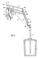
- a steel pan 1 and a diving lance 2 can be seen in the rest position, that is, in the raised position.
- the immersion lance 2 is connected to the device according to the invention via a fixed triangle 11.
- a bracket 3 is rotatably arranged via, for example, ball bearings.
- a hydraulically actuated cylinder 13 is also attached to the console 3 and causes the immersion lance 2 to be raised or lowered. When the immersion lance 2 is in the rest position, the cylinder piston rod 14 is in the extended position.
- An arm 4 is provided on the console 3 itself via an axis 15b, which arm is connected at its upper end to a second arm 5 via a further axis 15g.
- the diving lance holder 11 is articulated via an axis 15j.
- a guide arm 7 engages the piston rod 14 at one end via an axis 15c and is connected to the arm 5 at its other end via a further axis 15h. It should be noted here that the guide arm 7 is absolutely parallel to the arm 4.
- a second guide arm 6 connects the arm 4 to the guide arm 7 via two axes 15d and 15e. The guide arm 6 is also arranged parallel to the arm 5. In order to avoid a possible deviation of the diving lance 2 during the lowering or lifting from the vertical axis, it is necessary that the centers of the axes 15b, 15c and 15j are on an imaginary line 8.
- the two axes 15c and 15e could be designed as a single one, whereby the condition that the guide arm 6 is parallel to the arm 5 must still be fulfilled. This will of course shift the point of attack 15d on the arm 4. For design reasons, however retain the alternative shown in the figures.
- a guide which essentially consists of two guide rods 9 and 10 which are connected to one another via an axis 15f.
- the guide rod 9 is connected at its end opposite the axis 15f to the bracket 3 via an axis 15a and the guide rod 10 is connected to the rope lance holder 11 via an axis 15i.
- the axes 15f and 15g are connected to one another via a connecting member 17. It should also be emphasized that the imaginary lines between the axes 15f and lSg and between the axes 15i and 15j are parallel to the cylinder 13 or the piston rod 14.
- an adaptation device 16 is preferably provided comprising a set screw as a further fastening.
- the rotation of the console 3 with the entire device about the axis 12 can be achieved by a device known per se, for. B. via hydraulic cylinder or electric motor with gear.
- the position of the immersion lance 2 can be displayed continuously, for example via an angle sensor in the axis 15a or 15b.
- Figure 2 shows the diving lance 2 in the working position, i.e. inserted into the steel pan 1. It should be noted here that the piston rod 14 has moved into the cylinder 13. However, the piston rod 14 could easily be brought into any position between the rest and working positions.
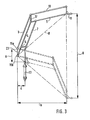
- FIG. 3 shows a schematic representation of the arrangement between the hydraulic cylinder 13 and the immersion lance holder 11.
- the vertical connecting line 23 between the two axes 1Sa and 15b is assumed as the reference line.
- the ratio of the distance a between the hydraulic cylinder 13 and the reference line 23 to the distance b between the lance holder 11 and the reference line 23 is equal to the ratio of the stroke A of the hydraulic cylinder 13 to the stroke B of the submersible lance holder 11
- the optimal conditions between the individual values specified and the force of the hydraulic cylinder can be determined.
- FIG. 4 shows a schematic illustration of the influence of a horizontal displacement of the hydraulic cylinder 13 on the immersion lance holder 11, which is shown only as a line in this figure.
- a displacement of the cylinder 13 from position 13a to position 13b means an increase in the distance to the reference line 23 from a to a le .
- this displacement means a displacement of the distance to the reference line 23 from b to b l .
- the ratio a to a 1 is equal to the ratio b to b 1 .
Landscapes
- Engineering & Computer Science (AREA)
- Chemical & Material Sciences (AREA)
- Materials Engineering (AREA)
- Metallurgy (AREA)
- Organic Chemistry (AREA)
- Mechanical Engineering (AREA)
- General Engineering & Computer Science (AREA)
- Manufacturing & Machinery (AREA)
- Treatment Of Steel In Its Molten State (AREA)
- Processing Of Solid Wastes (AREA)
- Feeding, Discharge, Calcimining, Fusing, And Gas-Generation Devices (AREA)
- Furnace Charging Or Discharging (AREA)
Priority Applications (1)
| Application Number | Priority Date | Filing Date | Title |
|---|---|---|---|
| AT82100134T ATE8665T1 (de) | 1981-01-26 | 1982-01-11 | Vorrichtung zum einblasen von substanzen in eine stahlschmelze. |
Applications Claiming Priority (2)
| Application Number | Priority Date | Filing Date | Title |
|---|---|---|---|
| LU83090A LU83090A1 (de) | 1981-01-26 | 1981-01-26 | Einrichtung zum einblasen von produkten in die stahlschmelze |
| LU83090 | 1981-01-26 |
Publications (3)
| Publication Number | Publication Date |
|---|---|
| EP0056944A2 true EP0056944A2 (fr) | 1982-08-04 |
| EP0056944A3 EP0056944A3 (en) | 1982-08-18 |
| EP0056944B1 EP0056944B1 (fr) | 1984-07-25 |
Family
ID=19729573
Family Applications (1)
| Application Number | Title | Priority Date | Filing Date |
|---|---|---|---|
| EP82100134A Expired EP0056944B1 (fr) | 1981-01-26 | 1982-01-11 | Dispositif pour injecter des matières dans un bain d'acier |
Country Status (5)
| Country | Link |
|---|---|
| EP (1) | EP0056944B1 (fr) |
| AT (1) | ATE8665T1 (fr) |
| AU (1) | AU7929282A (fr) |
| DE (1) | DE3260409D1 (fr) |
| LU (1) | LU83090A1 (fr) |
Cited By (1)
| Publication number | Priority date | Publication date | Assignee | Title |
|---|---|---|---|---|
| CN102756119A (zh) * | 2012-07-14 | 2012-10-31 | 马鞍山市博威液压机械制造有限责任公司 | 一种扒杆伸缩式液压扒渣机 |
Family Cites Families (6)
| Publication number | Priority date | Publication date | Assignee | Title |
|---|---|---|---|---|
| US3063699A (en) * | 1960-12-01 | 1962-11-13 | Robert C Read | Mobile apparatus for lancing molten mixtures |
| US3358985A (en) * | 1964-04-17 | 1967-12-19 | Nat Steel Corp | Apparatus for conveying fluid toward a region of high temperature |
| US3342471A (en) * | 1964-06-22 | 1967-09-19 | Kaiser Ind Corp | Oxygen lance assembly |
| US3891196A (en) * | 1974-01-21 | 1975-06-24 | Thyssen Niederrhein Ag | Apparatus for treating a melt |
| AT336900B (de) * | 1974-04-04 | 1977-05-25 | Vmw Ranshofen Berndorf Ag | Vorrichtung zur einbringung von gasen in flussigkeiten, insbesondere schmelzen |
| LU80692A1 (de) * | 1978-12-21 | 1980-07-21 | Arbed | Verfahren und vorrichtung zum entschwefeln von eisenschmelzen |
-
1981
- 1981-01-26 LU LU83090A patent/LU83090A1/de unknown
-
1982
- 1982-01-08 AU AU79292/82A patent/AU7929282A/en not_active Abandoned
- 1982-01-11 EP EP82100134A patent/EP0056944B1/fr not_active Expired
- 1982-01-11 AT AT82100134T patent/ATE8665T1/de not_active IP Right Cessation
- 1982-01-11 DE DE8282100134T patent/DE3260409D1/de not_active Expired
Cited By (2)
| Publication number | Priority date | Publication date | Assignee | Title |
|---|---|---|---|---|
| CN102756119A (zh) * | 2012-07-14 | 2012-10-31 | 马鞍山市博威液压机械制造有限责任公司 | 一种扒杆伸缩式液压扒渣机 |
| CN102756119B (zh) * | 2012-07-14 | 2014-06-11 | 马鞍山市博威液压机械制造有限责任公司 | 一种扒杆伸缩式液压扒渣机 |
Also Published As
| Publication number | Publication date |
|---|---|
| AU7929282A (en) | 1982-08-05 |
| LU83090A1 (de) | 1982-09-10 |
| ATE8665T1 (de) | 1984-08-15 |
| EP0056944A3 (en) | 1982-08-18 |
| EP0056944B1 (fr) | 1984-07-25 |
| DE3260409D1 (en) | 1984-08-30 |
Similar Documents
| Publication | Publication Date | Title |
|---|---|---|
| DE2544525C3 (de) | Mobildrehkran | |
| DE69217336T2 (de) | Fahrzeug zum automatischen Verlegen von Schienen auf welchen sich das Fahrzeug fortbewegt; und Schiene für diesen Zweck | |
| DE10026098B4 (de) | Vorrichtung zur automatischen Entnahme von Gegenständen aus Behältern | |
| EP0814052A1 (fr) | Plate-forme de travail mobile | |
| DE3721673C2 (de) | Vorrichtung am Führerhaus eines Kranes | |
| DE3426287C2 (de) | Verfahren zur Einstellung eines Deckels eines Kraftwagens und Anschlag zur Durchführung des Verfahrens | |
| DE3220744A1 (de) | Schmelz- und giessanlage fuer vakuum- oder schutzgasbetrieb mit mindestens zwei kammern | |
| EP0056944B1 (fr) | Dispositif pour injecter des matières dans un bain d'acier | |
| DE2419359A1 (de) | Stuetzplattform fuer lasten | |
| DE4206632C2 (de) | Maschine zur Unterhaltung einer Fahrleitung | |
| DE2819394A1 (de) | Verfahren und vorrichtung zur kontrolle und messung des lenkungs- und vorderachsspieles bei der sicherheitsinspektion von kraftfahrzeugen | |
| EP0056942B1 (fr) | Installation de fixation et de changement des lances immergées | |
| EP0808654B1 (fr) | Dispositif d'accrochage | |
| DE69411370T2 (de) | Einschlaggraviervorrichtung | |
| DE202023105578U1 (de) | Eine Art von Stahlbogenbrücke mit großer Spannweite, die mit einer einzigen Halterung ausgestattet ist | |
| DE4302421C2 (de) | Zweistöckige Parkeinrichtung | |
| DE2700284A1 (de) | Vorrichtung zur befoerderung von insbesondere kleinen gegenstaenden in allen richtungen | |
| DE20120958U1 (de) | Armlehne für ein Kraftfahrzeug | |
| DE3929139C2 (fr) | ||
| DE3726997C2 (de) | Brückenkran mit gewölbter Brücke | |
| DD155159A5 (de) | Drehkran | |
| DE2307183C3 (de) | Pedalanordnung, insbesondere für gepanzerte Fahrzeuge | |
| DE2653313C2 (de) | Deckelhebeeinrichtung für Koksöfen | |
| EP0284808A2 (fr) | Machine d'usinage par étincelles | |
| DE2051853A1 (de) | Vorrichtung zum Abstützen des Geschützrohres von Kampffahrzeugen |
Legal Events
| Date | Code | Title | Description |
|---|---|---|---|
| PUAI | Public reference made under article 153(3) epc to a published international application that has entered the european phase |
Free format text: ORIGINAL CODE: 0009012 |
|
| PUAL | Search report despatched |
Free format text: ORIGINAL CODE: 0009013 |
|
| AK | Designated contracting states |
Designated state(s): AT BE DE FR GB IT NL |
|
| AK | Designated contracting states |
Designated state(s): AT BE DE FR GB IT NL |
|
| 17P | Request for examination filed |
Effective date: 19821115 |
|
| ITF | It: translation for a ep patent filed | ||
| GRAA | (expected) grant |
Free format text: ORIGINAL CODE: 0009210 |
|
| AK | Designated contracting states |
Designated state(s): AT BE DE FR GB IT NL |
|
| REF | Corresponds to: |
Ref document number: 8665 Country of ref document: AT Date of ref document: 19840815 Kind code of ref document: T |
|
| REF | Corresponds to: |
Ref document number: 3260409 Country of ref document: DE Date of ref document: 19840830 |
|
| ET | Fr: translation filed | ||
| PLBE | No opposition filed within time limit |
Free format text: ORIGINAL CODE: 0009261 |
|
| STAA | Information on the status of an ep patent application or granted ep patent |
Free format text: STATUS: NO OPPOSITION FILED WITHIN TIME LIMIT |
|
| 26N | No opposition filed | ||
| ITTA | It: last paid annual fee | ||
| PGFP | Annual fee paid to national office [announced via postgrant information from national office to epo] |
Ref country code: FR Payment date: 19921204 Year of fee payment: 12 |
|
| PGFP | Annual fee paid to national office [announced via postgrant information from national office to epo] |
Ref country code: DE Payment date: 19921215 Year of fee payment: 12 |
|
| PGFP | Annual fee paid to national office [announced via postgrant information from national office to epo] |
Ref country code: GB Payment date: 19930108 Year of fee payment: 12 |
|
| PGFP | Annual fee paid to national office [announced via postgrant information from national office to epo] |
Ref country code: AT Payment date: 19930131 Year of fee payment: 12 Ref country code: NL Payment date: 19930131 Year of fee payment: 12 |
|
| PGFP | Annual fee paid to national office [announced via postgrant information from national office to epo] |
Ref country code: BE Payment date: 19930215 Year of fee payment: 12 |
|
| PG25 | Lapsed in a contracting state [announced via postgrant information from national office to epo] |
Ref country code: AT Effective date: 19940111 Ref country code: GB Effective date: 19940111 |
|
| PG25 | Lapsed in a contracting state [announced via postgrant information from national office to epo] |
Ref country code: BE Effective date: 19940131 |
|
| BERE | Be: lapsed |
Owner name: PAUL WURTH S.A. Effective date: 19940131 |
|
| PG25 | Lapsed in a contracting state [announced via postgrant information from national office to epo] |
Ref country code: NL Effective date: 19940801 |
|
| GBPC | Gb: european patent ceased through non-payment of renewal fee |
Effective date: 19940111 |
|
| NLV4 | Nl: lapsed or anulled due to non-payment of the annual fee | ||
| PG25 | Lapsed in a contracting state [announced via postgrant information from national office to epo] |
Ref country code: FR Effective date: 19940930 |
|
| PG25 | Lapsed in a contracting state [announced via postgrant information from national office to epo] |
Ref country code: DE Effective date: 19941001 |
|
| REG | Reference to a national code |
Ref country code: FR Ref legal event code: ST |