EP0057005A1 - Elektrisch betriebener Angelleinenbefestiger - Google Patents
Elektrisch betriebener Angelleinenbefestiger Download PDFInfo
- Publication number
- EP0057005A1 EP0057005A1 EP82100491A EP82100491A EP0057005A1 EP 0057005 A1 EP0057005 A1 EP 0057005A1 EP 82100491 A EP82100491 A EP 82100491A EP 82100491 A EP82100491 A EP 82100491A EP 0057005 A1 EP0057005 A1 EP 0057005A1
- Authority
- EP
- European Patent Office
- Prior art keywords
- fishline
- tier
- tying
- wheel
- guide slit
- Prior art date
- Legal status (The legal status is an assumption and is not a legal conclusion. Google has not performed a legal analysis and makes no representation as to the accuracy of the status listed.)
- Granted
Links
Images





Classifications
-
- A—HUMAN NECESSITIES
- A01—AGRICULTURE; FORESTRY; ANIMAL HUSBANDRY; HUNTING; TRAPPING; FISHING
- A01K—ANIMAL HUSBANDRY; AVICULTURE; APICULTURE; PISCICULTURE; FISHING; REARING OR BREEDING ANIMALS, NOT OTHERWISE PROVIDED FOR; NEW BREEDS OF ANIMALS
- A01K91/00—Lines
- A01K91/03—Connecting devices
- A01K91/04—Connecting devices for connecting lines to hooks or lures
Definitions
- the present invention generally relates to an electrically operated tier and, .more particularly, to an electrically operated, hand-held tier for tying a fishhook to a length of fishline.
- the present invention has been developed with a view to substantially eliminating these disadvantages and inconveniences inherent in the prior art tier and has for its essential object to provide an electrically operated fishline tier with with even laymen as well as those who are not good at a fine hand work and those who are short-sighted can make a knot necessary to secure the fishhook to the fishline.
- Another important object of the present invention is to provide an electrically operated fishline tier of the type referred to above, which is handy in structure and reliable in operation.
- the present invention provides an electrically operated tier which comprises a generally elongated, flattened housing having a bearing boss and a first guide slit means defined therein, said first guide slit means extending exteriorly of the housing and terminar- ing at a position spaced the maximum possible distance from the longitudinal axis of the bearing boss; a drive motor housed in the housing; a tying wheel rotatably mounted on the bearing boss with a portion thereof exposed to the outside of the housing, said tying wheel having one annular end face formed with an annular projection protruding therefrom in coaxial relation thereto and also having a second guide slit means defined therein, said second guide slit means extending in a radial direction completely across the tying wheel, said annular projection having a detent recess defined therein; a transmission means housed in the housing for transmitting a drive of the motor to the tying wheel to rotate the tying wheel in one direction; an anchoring member rigidly mounted on the other annul
- any commercially available battery preferably a single 1.5 volt, AM-3 battery, will serve the purpose. Accordingly, the machine according to the present invention is compact in structure and handy, giving a pleasant appearance to fishermen either less experienced or experienced.
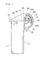
- an electrically operated tier comprises a generally elongated casing 2 having a cover plate .1 removably fitted to the casing 2.
- the casing has a battery chamber defined at 3 and accommodates therein a drive motor 4 at a substantially intermediate portion thereof, which motor 4 may be rigidly mounted in the casing 2.
- the drive motor 4 has a drive shaft 4a on which a worm gear 5 is pressure fitted for rotation together therewith.
- the tier also comprises a tying wheel 6 of generally split-ring shape having its outer periphery formed with gears adapted to mesh with the worm gear 5 and also having a radially extending guide slit 6c defined therein.
- a tying wheel 6 of generally split-ring shape having its outer periphery formed with gears adapted to mesh with the worm gear 5 and also having a radially extending guide slit 6c defined therein.
- one end face of the tying wheel assembly 6 has an annular projection 6b protruding outwardly therefrom in coaxial relation thereto, said annular projection 6b having a detent recess 6a which is defined therein so as to extend radially inwardly from the outer peripheral face thereof.
- This detent recess 6a is engageable with a pawl 7a integral with a manipulatable switching lever 7 as will be described later.
- the opposite end face of the tying wheel assembly 6 has a platform 8 protruding laterally outwardly therefrom in a direction opposite to the annular projection 6b and carries an anchoring member 9 riveted at 9a to the platform 8.
- the anchoring member 9 is preferably made of a generally U-shaped leaf spring and is used for the anchoring of one end of a fishline or fishing cord thereto.
- This anchoring member 9 may be made of a rubber block so far as it has a slit effective to retain that one end of the fishline.
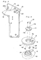
- the tying wheel assembly 6 is, as best shown in Fig. 4, rotatably mounted on a bearing boss 10 formed integrally with the casing 2 so as to protrude into the interior of the casing 2, said bearing boss 10 having a diameter substantially equal to the inner diameter of the tying wheel assembly 6.
- the bearing boss 10 projects coaxially through the wheel assembly 6 with its free end face having a retainer disc 11 which is secured thereto by means of set screws 12, such that the wheel assembly 6 will not separate from the bearing boss 10 unless the retainer disc 11 is removed.
- the retainer disc 11 has a receptacle lla defined therein at the center there-' of for receiving one end 29a of a fishhook 29 (Fig.
- the retainer disc 11 is so secured to the bearing boss 10 by means of the set screws 12 that, when and so long as the drive motor 4 is brought to a halt, the guide slit 6c in the wheel assembly 6 and the guide slit llb in the retainer disc 11 are aligned with each other as best shown in Fig. 2.
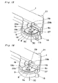
- the drive motor 4 which may be a D.C. micromotor, has positive and negative input terminals, the positive input terminal being connected by means of a lead wire 13a to a positive terminal member 14 facing the battery chamber 3 and also to a NC terminal 15a of a microswitch 15 whereas the negative input terminal is connected to a common terminal 15b of the microswitch 15 through a lead wire 13b.
- the microswitch 15 has a further terminal, i.e., a NO terminal 15c connected through a lead wire to a negative terminal member 16 which faces the battery chamber 3 in opposed relation to the positive terminal member 14 and which may be in the form of a coiled wire. This wiring circuit is best shown in Fig. 18 and will be described in detail later.
- a microswitch having two terminals may be employed.
- the employment of the microswitch of the illustrated type and, hence, of the wiring system shown in Fig. 18 is preferred because of the reason which will become clear from the subsequent description.
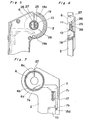
- the manipulatable switching lever 7 is of a generally L-shaped configuration having one arm carrying the pawl 7a at its free end and another arm extending generally at right angles to said one arm and having a slope defined at 7b.
- the slope 7b at the free end of said other arm of the switching lever 7 is so shaped and so positioned that, when the switching lever 7 is shifted from an off position, shown in Fig. 7., to an on position shown in Fig. 8 by the application of an external sliding force to a slide knob 7c integral with the switching lever 7, an actuating element 15d of the microswitch 15 is inwardly collapsed to switch the microswitch 15 on.
- the pawl 7a is disengaged from the detent recess 6a in the annular projection 6b fast with the tying wheel assembly 6 to permit the wheel assembly 6 to be driven in one direction at the time the microswitch 15 is turned on.
- a driving force necessary to rotate the wheel assembly 6 is transmitted from the motor 4 through the engagement between the worm gear 5 and the gears on the outer periphery of the wheel assembly 6.
- the microswitch 15 since the switching lever 7 is normally biased to the off position by the action of a biasing spring 17, for example, a compression spring so far shown, the microswitch 15 is turned on and, therefore, the motor 4 is driven to rotate the wheel assembly 6 so long as the external sliding force is applied to the slide knob 7c. Release of the external sliding force from the slide knob 7c results in deenergization of the motor 4, it being, however, to be noted that the actuating element 15d of the microswitch 15 is kept depressed in contact with the slope 7b until the detent recess 6b in the annular projection 6a being rotated together with the wheel assembly 6 is brought into alignment with the pawl 7a.
- a biasing spring 17 for example, a compression spring
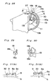
- the casing 2 carries a slider 18 movable between receiving and transfer positions along an arcuate path externally along and partially following the outer periphery of the wheel assembly 6. More specifically, the casing 2 has a curved wall encircling substantially halfway the outer periphery of the wheel assembly 6 and having its opposite lateral side faces formed with respective arcuate guide grooves 19.
- the slider 18 has a pair of bearing pins 18a, as best shown in Figs. 29 and 30, extending in the opposite directions close towards each other and is mounted on the casing 2 with said bearing pins 18a movably engaged in the respective arcuate guide grooves 19.
- One wall portion defining the respective arcuate guide groove 19 is formed with a pair of detent projections 19a and 19b so spaced that the slider 18 can be clicked to occupy the receiving and transfer positions one at a time.
- the slider 18 is held firmly in the transfer position with the bearing pins 18a trapped by the respective detent projections 19a.
- the slider 18 can be held firmly in the receiving position with the bearing pins 18a trapped by the respective detent projections 19b once it has been moved back to the receiving position.
- the cover plate 1 carries a fishhook holder for holding the fishhook 29 firmly in position during the tying operation.
- This fishhook holder comprises a pivotable lever 20 which has one end receiving a knob 21 pressure fitted thereto and the other end formed into a generally V-shaped finger 20a.
- a portion of the pivotable lever 20 adjacent the finger 20a is supported on a bearing pin la, fast and integral with the cover plate 1, for pivotal movement between retained and release positions about such bearing pin la.
- This pivotable lever 20 is normally biased to assume the retained position by the action of a biasing spring 22, for example, a V-shaped wire spring so far illustrated, or any other spring element such as a leaf spring.
- a biasing spring 22 for example, a V-shaped wire spring so far illustrated, or any other spring element such as a leaf spring.
- the cover plate 1 has a slot defined at 23, leaving a rib 24 on an outer side portion of the cover plate 1 adjacent the wheel assembly 6, said rib having an outwardly tapered end 24a terminating in continuance with a portion thereof adjacent the support table lb.
- the function of the rib 24 will be described later.
- the bearing boss 10 fast and integral with the casing 2 has a generally rectangular socket 25 defined therein for the accommodation of a fishline retainer 28 therein.
- This rectangular socket 25 is continued to a guide slit 27, defined in the casing 2 so as to extend in parallel to the longitudinal axis of the casing 2, through a guide slit 26 defined in a wall portion of the bearing boss 10.
- the guide slit 27 defined in the casing 2 has a length larger than the sum of the respective lengths of the guide slit 6c in the wheel assembly 6 and the guide slit llb in the retainer disc 11 and is so designed that, when and so long as the wheel assembly 6 is in a stop position with the guide slit 6c aligned with both of the guide slit llb in the retainer disc 11 and the guide slit 27 in the casing 2, a length of fishline 20 (Fig.
- the length of fishline 30 so inserted and so passed extends at a position offset the slightest possible distance from the longitudinal axis of the bearing boss 10 or from the receptacle lla.
- the fishline retainer 28 accommodated within the rectangular socket 25 is, so far illustrated, in the form of a generally U-shaped wire spring and is used to retain a portion of the length of fishline 30, which passes through the guide slit llb in the retainer disc 11 and the guide slit 27 in the casing 2, in position in cooperation with a wall portion defining the rectangular socket 25.
- This retainer 28 is confined within the socket 25 with no possible separation thereof out of the socket 25 because of the retainer disc 11 secured to the bearing boss 10 as hereinbefore described. It is to be noted that this retainer 28 may not be always necessary and, in the case where it is not employed, the rectangular socket 25 may also be omitted. It is also to be noted that, instead of the wire spring, a leaf spring may be employed for the fishline retainer 28.
- the guide slits 6c, llb and 27 have an equal width which is slightly greater than the maximum possible diameter Y (Fig. 10) of the fishline 30.
- the gears on the outer periphery of the wheel assembly 6 should be so selected that the bottom of the dale between each adjacent two gears has a width Z equal to the width X of the guide slit 6c as best shown in Fig. 10.
- the first thing for an amateur fisherman or an operator to do is to set the fishhook 29 in the tier.
- the operator of the tier according to the present invention should press the knob 21 so as to cause the pivotable lever 20 to pivot from the retained position towards the release position against the biasing spring 22 with the finger 20a consequently separating away from the supporttable lb integral with the cover plate 1.
- the knob 21 while the knob 21 is kept pressed, the operator mounts the fishhook 29 with the free end 29a thereof inserted into the receptacle lla and, thereafter, the external pressing force is released from the knob 21 to allow the pivotable lever 20 to return to the retained position by the action of the biasing spring 22.
- the fishhook 29 is firmly retained by the tier in such a manner that the stem of the fishhook 29 is clamped between the V-shaped finger 20a of the pivotable lever 20 and the support table lb on the cover plate 1 while the point 29b is loosely received and guarded in the slot 23 in the cover plate 1, as best shown in Figs. 11 and 19.
- the fishhook 29 is shown in three types of different sizes, small, medium and large, and, in the case of the large fishhook 29, the point 29b is, when the fishhook 29 is so retained as hereinbefore described, held in contact with the rib 24 without being inserted into the slot 23.
- a length of fishline 30 extending from a reel (not shown) is wound around the wheel assembly 6 in the manner which will now be described.
- the length of fishline 30 is laid through the guide slits 27, 6c, llb and 26, which are all aligned with one another when and so long as the wheel assembly 6 is in the stop position, so as to pass across the wheel assembly 6 substantially coaxially with the center of rotation of the wheel assembly 6 or the bearing boss 10.
- a free end portion of the length of fishline 30 opposite to the reel (not shown) from which it extends outwards is located on one side of the tier adjacent the anchoring member 9 and is anchored to the anchoring member 9 in the form as sandwiched between the anchoring member 9 and the platform 8 as clearly shown in Fig. 13. It is to be noted that, when to anchor the free end portion of the length of fishline 30 in the manner described above, care is required to anchor to the anchoring member 9 a portion of the fishline 30 spaced a certain distance, say, 1 to 3 cm, inwardly from the free end extremity 30a thereof depending on the diameter of the stem of the fishhook 29 and the number of turns desired to be made.
- the portion of the fishline 30 which is turned around the slider 18 in the receiving position will not be loosened or slackened even when and after an external pulling force applied during the winding of the length of fishline 30 has been released from the portion of the fishline 30 adjacent the reel which extends outwards from the tier on one side of the wheel assembly 6 opposite to the free end portion thereof.
- the length of fishline 30 is completely set to the electrically operated tier preparatory to the formation of a knot necessary to secure the length of fishline 30 to the fishhook 29.
- the slide knob 7c integral with the switching lever 7 is pressed to move downwards as viewed in Figs. 2 and 7 to allow the slope 7b on the one hand to turn the microswitch 15 on and the pawl 7a on the other hand to disengage from the detent recess 6a in the tying wheel assembly 6. Therefore, as shown in Fig. 7, the drive motor 4 is energized to drive the wheel assembly 6 in one direction about the bearing boss 10. So far shown, the wheel assembly 6 is rotated in a clockwise direction as viewed in Figs. 1 and 2 about the bearing boss 10 although it may be in a counterclockwise direction.
- the switching lever 7 is held in the on position against the biasing spring 17 even though the external sliding force applied to the slide knob 7c to move the latter downwards has been released therefrom. As hereinbefore described, it is when the pawl 7a fast with the switching lever 7 is engaged into the detent recess 6a that the switching lever 7 is returned to the off position as biased by the biasing spring 17 with the microswitch 15 consequently turned off to deenergize the motor 4.
- the slide knob 7c is kept moved downwards as viewed in Figs. 1 and 2 by the application of the external sliding force before the wheel assembly 6 completes five or six rotations about the bearing boss 11 and the external sliding force is released from the knob 7c after the wheel assembly 6 being rotated enters the fifth or sixth rotation.
- the pawl 7a is engaged into the detent recess 6a to bring the wheel assembly 6 to a halt with the switching lever 7 consequently returned to the off position as biased by the biasing spring 17. Therefore, simultaneously with the engagement of the pawl 7a into the detent recess 6a, the microswitch 15 is turned off to deenergize the motor 4.
- the slider 18 in the receiving position is manually moved towards the transfer position along the arcuate guide grooves and is then clicked to the transfer position with the bearing pins 18a overriding the detent projections 19b.
- that portion of the fishline 30 turned around the slider 18 is brought to a position ready to enter the guide slit 27 as best shown in Fig. 15.
- the microswitch 15 has been described as having the NC terminal 15a connected to the positive terminal member 14 which is also connected with a positive terminal of the motor 4, the common terminal 15b connected to a negative terminal of the motor 4, and the NO terminal 15c connected to the negative terminal member 16.
- the common terminal 15b is electrically connected to the NO terminal 15c to complete a power supply circuit to energize the motor 4.
- the motor 4 can be brought to a halt with the wheel assembly 6 held definitely at the stop position. This is important in that the guide slit 6c in the wheel assembly 6 can be always registered in line with the guide slit llb in the retainer disc 11 and also with the guide slit 27 in the casing wall.
- the worm gear 5 being driven by the motor 44 tends to override the gears on the wheel assembly 6 at the instant the pawl 7a is engaged into the detent recess 6a to bring the wheel assembly 6 to a halt.
- the motor 4 is preferably mounted on the casing 2 in a movable manner.
- the casing 2 has a pair of spaced motor supports 31 and 36 integrally formed therewith and protruding outwardly therefrom at right angles thereto, said motor support 31 being substantially L-shaped whereas the support 36 is substantially U-shaped as best shown in Fig. 22.
- the motor 4 is mounted on the casing 2 with its opposite ends received in the associated motor supports 31 and 36.
- a biasing spring which is in the form of a wire spring 32 is employed.
- This wire spring 32 has a mounting eye formed at 32a and one end 32b so shaped as to encircle or catch the body of the motor 4 and is disposed in the casing 4 with the eye 32a mounted on a support stud 33 integral with the casing 2.
- the one end 32b of the wire spring 32 is engaged to the motor 4 while the other end thereof is engaged to a side wall portion of the casing 2 so that a biasing force exerted by the wire spring 32 can be applied to the motor 4 and then to the worm gear 5 to urge the latter towards the wheel assembly 6 in a direction shown by the arrow B.
- the motor support 31 integral with the casing 2 is so shaped as to regulate the force of contact of the worm gear 5 to the wheel assembly 6 and is, for this purpose, generally L-shaped.
- the worm gear 5 tending to override the gears on the wheel assembly 6 incident to the further rotation of the motor 4 under the influence of the inertia force disengage from the gears on the wheel assemby 6, separating away from the wheel assembly 6 against the wire spring 32 accompanied by the corresponding displacement of the motor 4 in a direction shown by the arrow A in Fig. 22.
- the motor support 36 provides a fulcrum about which the body of the motor 4 pivots to permit the disengagement of the worm gear 5 away from the wheel assembly 6 against the wire spring 32.
- the worm gear 5 can be returned to the original position to establish its engagement with the gears on the wheel assembly 6. More specifically, where the voltage of the battery is relatively high and the load imposed by the fishline 30 on the wheel assembly 6 is relatively small, it may occur that the worm gear 5 is temporarily disengaged from the gears on the wheel assembly 6 and is thereafter forced by the wire spring 32 to engage the.-gears on the.wheel assembly 6 at a position one pitch displaced, substantially as shown in Fig. 23.
- the provision of the wire spring 32 rather than the fixed mounting of the motor relative to the casing 2 is advantageous in that any possible breakage of some of the gears on one or both of the worm gear 5 and the wheel assembly 6 can also be avoided. It is to be noted that, even when the condition shown in Fig. 24 is established, the worm gear 5 can be brought into engagement with the gears on the wheel assembly 6 by the action of the wire spring 32 when the motor 4 is energized during the next succeeding cycle of operation.
- a leaf spring may be employed as shown by 34 in Figs. 25 and 26.
- the slider 18 is so designed that, when it is in the receiving position, the support surface 18b which the length of fishline 30 is turned around and extends across in the manner as hereinbefore described lies in a plane at an angle greater by a than the tangential angle 9 of 90°. Therefore, when that portion of fishline is turned around the slider 18 so as to extend across the support surface 18b, there is no possibility that that portion of fishline 30 may slip off the support surface 18b in a direction away from the slider 18. However, when the slider 18 has been moved to the transfer position as shown in Fig.
- the support surface 18b lies in a plane at an angle smaller by S than the tangential angle 0. This is because a portion of the casing wall confronting the guide slit 27 adjacent the transfer position of the slider 18 is so inclined that, when the slider 18 arrives at the transfer position, the slider 18 can pivot about the bearing pins 18a in a direction with the support surface 18b inclined downwards towards the guide slit 27 as best shown in Fig. 28. Therefore, at the transfer position of the slider 18, that portion of fishline 30 can slip off the support surface 18b onto the guide slit 27 when a slight pull is given to the portion of fishline 30 extending outwardly from the guide slit 27, thereby forming the knot on the length of fishline 30.
- the provision of the slider 18 is advantageous in that the shift of that portion of fishline 30 turned around and encircling the assembly of the casing 2 and the wheel assembly 6 towards a position immediately above the guide slit 27 can be facilitated merely by moving the slider 18 from the receiving position towards the transfer position, it may not be essential in the practice of the present invention because such shift can be done manually without the aid of the slider.
- the anchoring member 9 rigidly mounted on the tying wheel assembly 6 through the platform 8 integral with such wheel assembly 6.
- the anchoring member 9 is in the form of a generally U-shaped leaf spring having a pair of leg portions, one leg portion having one end secured to the platform 8 by means of the rivet 9a and the other end continued to the other leg portion which extends between said one leg portion and the platform 8 and terminates at a position spaced a distance from the rivet 9a.
- the anchoring member 9 By the action of the resiliency the anchoring member 9 has, the other leg portion thereof is urged to contact the surface of the platform 8 so that, when the free end portion of the fishline 30 is inserted in between the other leg.portion of the anchoring member 9 and the platform 8, it can be gripped therebetwen.
- the platform 8 has a stopper block 8a formed integrally therewith and protruding outwards from the surface of the platform 8 at a position laterally of the free end of the other leg portion of the anchoring member 9. As best shown in Fig. 31(b), this stopper block 8a is effective to avoid any possible through-pass of the free end portion of fishline 30 behond a critical limit.
- the electrically operated tier according to the present invention can be used even by laymen in tying a length of fishline to a fishhook. This is in contrast to the art of tying the length of fishline to the fishhook which has hitherto required a sophisticated and time-consuming skill. According to the present invention, turning the length of fishline after the fishhook has been set to the machine and letting the motor work will do all that is required to form the knot for securing the length of fishline to the fishhook.
Landscapes
- Life Sciences & Earth Sciences (AREA)
- Environmental Sciences (AREA)
- Animal Husbandry (AREA)
- Biodiversity & Conservation Biology (AREA)
- Mechanical Means For Catching Fish (AREA)
- Processing Of Meat And Fish (AREA)
Applications Claiming Priority (10)
| Application Number | Priority Date | Filing Date | Title |
|---|---|---|---|
| JP10666/81 | 1981-01-26 | ||
| JP10664/81 | 1981-01-26 | ||
| JP10667/81 | 1981-01-26 | ||
| JP1066681A JPS6046932B2 (ja) | 1981-01-26 | 1981-01-26 | 電動式釣針の釣糸結び器 |
| JP1066481A JPS5925578B2 (ja) | 1981-01-26 | 1981-01-26 | 電動式釣針の釣糸結び器 |
| JP1066781A JPS5925580B2 (ja) | 1981-01-26 | 1981-01-26 | 電動式釣針の釣糸結び器 |
| JP54168/81U | 1981-04-14 | ||
| JP5416881U JPS57167683U (de) | 1981-04-14 | 1981-04-14 | |
| JP10808381A JPS5925581B2 (ja) | 1981-07-09 | 1981-07-09 | 電動式釣針の釣糸結び器 |
| JP108083/81 | 1981-07-09 |
Publications (2)
| Publication Number | Publication Date |
|---|---|
| EP0057005A1 true EP0057005A1 (de) | 1982-08-04 |
| EP0057005B1 EP0057005B1 (de) | 1985-07-31 |
Family
ID=27519199
Family Applications (1)
| Application Number | Title | Priority Date | Filing Date |
|---|---|---|---|
| EP82100491A Expired EP0057005B1 (de) | 1981-01-26 | 1982-01-25 | Elektrisch betriebener Angelleinenbefestiger |
Country Status (3)
| Country | Link |
|---|---|
| US (1) | US4401328A (de) |
| EP (1) | EP0057005B1 (de) |
| DE (1) | DE3264961D1 (de) |
Cited By (2)
| Publication number | Priority date | Publication date | Assignee | Title |
|---|---|---|---|---|
| CN105900949A (zh) * | 2016-04-26 | 2016-08-31 | 重庆大学 | 一种自动鱼钩绑线器 |
| CN106212402A (zh) * | 2016-07-22 | 2016-12-14 | 高郅学 | 一种绑钩器及操作方法 |
Families Citing this family (6)
| Publication number | Priority date | Publication date | Assignee | Title |
|---|---|---|---|---|
| US6543819B2 (en) * | 2001-04-02 | 2003-04-08 | John Hakimain | Necktie knotter |
| KR100804960B1 (ko) * | 2007-03-29 | 2008-02-20 | 이덕희 | 택 부착기의 매듭기의 교체장치 |
| US9332745B2 (en) * | 2013-08-13 | 2016-05-10 | Amal Mashhour | Knot tying tool |
| US9433198B2 (en) * | 2014-03-06 | 2016-09-06 | Phyllis D. O'Neal | Fishing line knotter |
| US9185894B1 (en) * | 2015-05-12 | 2015-11-17 | Abdulrahman KH. Almubaelesh | Automatic fish hook tying device |
| US10132017B1 (en) * | 2017-08-10 | 2018-11-20 | Abdulrahman Kh. Abdulaziz Almubaelesh | Fish hook tying tool |
Citations (3)
| Publication number | Priority date | Publication date | Assignee | Title |
|---|---|---|---|---|
| DE1226359B (de) * | 1965-08-13 | 1966-10-06 | Herbert Bernert | Vorrichtung zum Befestigen von Angelhaken an einer Angelschnur |
| US3520566A (en) * | 1967-10-28 | 1970-07-14 | Marcel Bovigny | Machine for tying fishing hooks |
| US3664005A (en) * | 1970-03-13 | 1972-05-23 | Ciatti Enzo | Device for fastening a hook to a fishing line |
Family Cites Families (9)
| Publication number | Priority date | Publication date | Assignee | Title |
|---|---|---|---|---|
| US1450941A (en) * | 1916-03-09 | 1923-04-10 | Barber Colman Co | Knotter |
| US1390103A (en) * | 1919-03-22 | 1921-09-06 | Automatic Machine Company Inc | Thread-knotter |
| US2865665A (en) * | 1956-01-13 | 1958-12-23 | Messa Daniele | Knotting device |
| DE1172193B (de) * | 1957-08-20 | 1964-06-11 | Carter Inc Ab | Handgeraet zum Verbinden von Fadenenden |
| US3166346A (en) * | 1962-05-12 | 1965-01-19 | Wildt Mellor Bromley Ltd | Knotter for fisherman's knots in the textile industry |
| US3667790A (en) * | 1971-01-25 | 1972-06-06 | John H Taylor | Knot winder for tying fish hooks |
| GB1367395A (en) * | 1971-03-25 | 1974-09-18 | Mes Dan Di Messa Pietro | Attachment for yarn spoolers for automatically forming a fisherman knot or the like |
| US3923588A (en) * | 1974-08-01 | 1975-12-02 | Deering Milliken Res Corp | Yarn splicer |
| US4030743A (en) * | 1976-05-24 | 1977-06-21 | Milliken Research Corporation | Synthetic yarn device |
-
1982
- 1982-01-20 US US06/341,150 patent/US4401328A/en not_active Expired - Fee Related
- 1982-01-25 EP EP82100491A patent/EP0057005B1/de not_active Expired
- 1982-01-25 DE DE8282100491T patent/DE3264961D1/de not_active Expired
Patent Citations (3)
| Publication number | Priority date | Publication date | Assignee | Title |
|---|---|---|---|---|
| DE1226359B (de) * | 1965-08-13 | 1966-10-06 | Herbert Bernert | Vorrichtung zum Befestigen von Angelhaken an einer Angelschnur |
| US3520566A (en) * | 1967-10-28 | 1970-07-14 | Marcel Bovigny | Machine for tying fishing hooks |
| US3664005A (en) * | 1970-03-13 | 1972-05-23 | Ciatti Enzo | Device for fastening a hook to a fishing line |
Cited By (3)
| Publication number | Priority date | Publication date | Assignee | Title |
|---|---|---|---|---|
| CN105900949A (zh) * | 2016-04-26 | 2016-08-31 | 重庆大学 | 一种自动鱼钩绑线器 |
| CN106212402A (zh) * | 2016-07-22 | 2016-12-14 | 高郅学 | 一种绑钩器及操作方法 |
| CN106212402B (zh) * | 2016-07-22 | 2019-01-15 | 高郅学 | 一种绑钩器及操作方法 |
Also Published As
| Publication number | Publication date |
|---|---|
| DE3264961D1 (en) | 1985-09-05 |
| US4401328A (en) | 1983-08-30 |
| EP0057005B1 (de) | 1985-07-31 |
Similar Documents
| Publication | Publication Date | Title |
|---|---|---|
| US4401328A (en) | Electrically operated fishline tier | |
| JPH0246295Y2 (de) | ||
| US4104791A (en) | Stripper for coated wires | |
| GB2141935A (en) | Dental floss holder/applicator | |
| US3690748A (en) | Motion picture camera with a fade-over device | |
| JPS5925578B2 (ja) | 電動式釣針の釣糸結び器 | |
| JPS5925580B2 (ja) | 電動式釣針の釣糸結び器 | |
| US4091515A (en) | Apparatus for mounting a connector to coated wires | |
| JPH04258240A (ja) | 電動式釣針の釣糸結び器 | |
| US3065314A (en) | Timed control mechanism | |
| JPS5925579B2 (ja) | 電動式釣針の釣糸結び器 | |
| JPS6046936B2 (ja) | 電動式釣針の釣糸結び器 | |
| US4573150A (en) | Self-holding switch for use in a sound reproducing device | |
| JPS5925577B2 (ja) | 電動式釣針の釣糸結び器 | |
| US2622706A (en) | Handle with cord control mechanism | |
| US3307991A (en) | Method and apparatus for winding toroidal coils | |
| US713500A (en) | Electric time-switch. | |
| JPS6046934B2 (ja) | 電動式釣針の釣糸結び器 | |
| JPS59161963A (ja) | 電話機のコ−ド巻取り装置 | |
| JPH0332328B2 (de) | ||
| JPS6046935B2 (ja) | 電動式釣針の釣糸結び器 | |
| KR20250155279A (ko) | 교체가능한 스풀과 배터리를 구비한 낚시용 릴 | |
| JPH0323127B2 (de) | ||
| DE1012086B (de) | Selbsttaetige Triebwerks-Endabstellung beim Wickeln von Faeden, Draehten oder Baendern | |
| KR900003167Y1 (ko) | 브이씨알의 급브레이크장치 |
Legal Events
| Date | Code | Title | Description |
|---|---|---|---|
| PUAI | Public reference made under article 153(3) epc to a published international application that has entered the european phase |
Free format text: ORIGINAL CODE: 0009012 |
|
| AK | Designated contracting states |
Designated state(s): DE FR GB |
|
| 17P | Request for examination filed |
Effective date: 19830201 |
|
| GRAA | (expected) grant |
Free format text: ORIGINAL CODE: 0009210 |
|
| AK | Designated contracting states |
Designated state(s): DE FR GB |
|
| REF | Corresponds to: |
Ref document number: 3264961 Country of ref document: DE Date of ref document: 19850905 |
|
| ET | Fr: translation filed | ||
| PLBE | No opposition filed within time limit |
Free format text: ORIGINAL CODE: 0009261 |
|
| STAA | Information on the status of an ep patent application or granted ep patent |
Free format text: STATUS: NO OPPOSITION FILED WITHIN TIME LIMIT |
|
| 26N | No opposition filed | ||
| PGFP | Annual fee paid to national office [announced via postgrant information from national office to epo] |
Ref country code: FR Payment date: 19940111 Year of fee payment: 13 |
|
| PGFP | Annual fee paid to national office [announced via postgrant information from national office to epo] |
Ref country code: GB Payment date: 19940117 Year of fee payment: 13 |
|
| PGFP | Annual fee paid to national office [announced via postgrant information from national office to epo] |
Ref country code: DE Payment date: 19940121 Year of fee payment: 13 |
|
| PG25 | Lapsed in a contracting state [announced via postgrant information from national office to epo] |
Ref country code: GB Effective date: 19950125 |
|
| GBPC | Gb: european patent ceased through non-payment of renewal fee |
Effective date: 19950125 |
|
| PG25 | Lapsed in a contracting state [announced via postgrant information from national office to epo] |
Ref country code: FR Effective date: 19950929 |
|
| PG25 | Lapsed in a contracting state [announced via postgrant information from national office to epo] |
Ref country code: DE Effective date: 19951003 |
|
| REG | Reference to a national code |
Ref country code: FR Ref legal event code: ST |