EP0057030A1 - Gleisstopfmaschine - Google Patents
Gleisstopfmaschine Download PDFInfo
- Publication number
- EP0057030A1 EP0057030A1 EP82200040A EP82200040A EP0057030A1 EP 0057030 A1 EP0057030 A1 EP 0057030A1 EP 82200040 A EP82200040 A EP 82200040A EP 82200040 A EP82200040 A EP 82200040A EP 0057030 A1 EP0057030 A1 EP 0057030A1
- Authority
- EP
- European Patent Office
- Prior art keywords
- tamping
- aggregate
- machine
- frame
- machine according
- Prior art date
- Legal status (The legal status is an assumption and is not a legal conclusion. Google has not performed a legal analysis and makes no representation as to the accuracy of the status listed.)
- Granted
Links
Images


Classifications
-
- E—FIXED CONSTRUCTIONS
- E01—CONSTRUCTION OF ROADS, RAILWAYS, OR BRIDGES
- E01B—PERMANENT WAY; PERMANENT-WAY TOOLS; MACHINES FOR MAKING RAILWAYS OF ALL KINDS
- E01B27/00—Placing, renewing, working, cleaning, or taking-up the ballast, with or without concurrent work on the track; Devices therefor; Packing sleepers
- E01B27/12—Packing sleepers, with or without concurrent work on the track; Compacting track-carrying ballast
- E01B27/13—Packing sleepers, with or without concurrent work on the track
- E01B27/16—Sleeper-tamping machines
Definitions
- the subject of the present invention is a machine for tamping railway tracks, in particular a machine for tamping, leveling and erecting railway tracks, comprising at least one aggregate of tamping movable longitudinally relative to the chassis of the machine and at least one pair of picks. cooperating with each other and adjustable in height.
- the tamping aggregate progressing step by step can move longitudinally on the frame of the machine in particular guides.
- Such a provision is however linked to adjustment problems.
- the tamping tools being then raised above the level of the tracks, the tamping aggregate is at the rear end of its path of movement on the chassis and must also be brought as quickly as possible at the anterior end of its path of travel, above the next cross member, then descended on this cross member; during the following tamping phase proper the tamping aggregate must be brought back with a speed corresponding to the speed of progression of the machine on the track. Controlling this movement and adjusting the tamping aggregate to the correct working position, however, presents difficulties in the case of an aggregate moving in a back and forth movement in guides.
- the object of the invention is to simplify such machines, both with regard to the adjustment and control of the tamping aggregate and with regard to its construction.
- the tamping machine is characterized in that the tamping aggregate is suspended pendularly about an axis transverse to the chassis of the machine, which comprises a device for pivoting the tamping aggregate around of its suspension axis.
- the packing aggregate can thus move like a pendulum in a vertical plane and relative to the chassis of the machine.
- This arrangement has several advantages.
- the exact rapid adjustment of the packing aggregate relative to the chassis of the machine by tilting this aggregate around a fixed axis relative to the chassis is substantially simpler to carry out than a displacement in translation of this aggregate on guide rails.
- the friction of rotation around an axis can be maintained a lot. lower than the friction of a rolling aggregate on guide rails.
- the acceleration and braking forces are much lower than the forces required to move the whole aggregate in a linear back and forth movement.
- the size of the tamping aggregate in the upper part of the machine is substantially smaller, since it is not necessary to provide space for the translational drive of this aggregate.
- the tamping tools are mounted on a support.
- support ' is vertically movable on a frame itself even mounted pendulumally on the chassis.
- Two columns can advantageously be fixed to the frame for guiding the support during the vertical displacement of the latter, these columns being provided with guide rollers at their lower ends, which roll on the rails.
- This ensures permanent guidance of the tamping aggregate, guidance which can be further facilitated by suspending its frame by means of a universal joint, which allows the latter to also move transversely relative to the machine, so that the frame with its packing aggregate can freely follow the movement of the guide rollers on the rails.
- the control of the tilting of the frame with the tamping aggregate is advantageously carried out by means of a jack attached on the one hand to the chassis and on the other hand to one of the columns.
- the device is advantageously automatically controlled, so that the uniform progression of the machine corresponding to the average working speed is controlled as a function of the minimum duration of a tamping cycle, or, which amounts to the same thing, as a function of the distance between two consecutive sleepers measured using a sleeper detector.
- FIG. 1 represents a machine for stuffing, leveling and dressing the tracks moving with a uniform speed on the tracks in the direction of the arrow.
- This machine comprises a chassis 2 provided with two sets of wheels 3 and 4 rolling on the tracks 5 and two command and control cabins 6 and 7 at the front and at the rear of the machine.
- In the middle of the frame 2 are mounted known leveling and straightening devices constituted by roller clamps 8, by means of which the machine ensures the leveling of the tracks, that is to say the planes to the desired height and simultaneously laterally erects these tracks.
- the roller clamps 8 are controlled automatically on the basis of measurements carried out by means of a reference system, respectively a measurement base, which is defined by reference points of the channel and delivers a reference quantity.
- a reference point A on the not yet corrected part of the track and, in the case of a straight line as the basis of measurement, a reference point C in the corrected part of the way.
- the reference points A and C are defined by means of measuring wheels 9 and 10 mounted on the chassis 2 of the machine and running on the rails 5.
- Another measuring point in the corrected part of the track can be defined by means of a movable equipment attached behind the machine. Close to the workplace, a point of measurement B, by means of a measurement wheel 11, which defines the shape of the rail immediately behind the leveling and straightening tools. The measured quantities are compared with the target quantity to control the roller clamps 8.
- the tamping aggregate 12 and its suspension are shown in more detail in FIG. 2.
- This tamping aggregate 12 has, on each side of a track 5, a pair of tamping tools 14 adjustable one relative to the other and provided with picks 16 sinking into the ballast on each side of a cross member 15.
- the tamping tools 14 of the two pairs are articulated to a common eccentric shaft 18 rotating in a support 17, the tamping tools 14 of each pair being constituted by two-arm levers which cross around the eccentric shaft 18.
- the support 17 is suspended from a frame 20 on which it is vertically movable by means of a hydraulic cylinder 19, the frame 20, as well as the end upper of the hydraulic cylinder 19, being capable of tilting about the transverse axis 13 perpendicular to the longitudinal direction of the track, in the direction of the double arrow, in a vertical plane.
- the frame 20 has a cross member 21 to which the hydraulic cylinder 19 is fixed, while the support 17 is fixed to the lower end of the piston rod 23 of the cylinder 19.
- each column 24 and 25 oriented parallel to the piston rod 23 and which are fixed to the cross member 21 of the frame 20.
- the lower ends of these columns are provided with guide rollers 26 and 27 rolling on the rail 5 and whose yokes can slide axially on the columns 24 and 25, during the tilting of the frame 20, by compressing springs.
- the support 17 slides on the column 24 by means of a guide sleeve 28, while on the other side it has a guide profile 29 which can slide on a conjugate profile 30 of the column 25.
- the upper ends opposite the picks 16, tamping tools 14 of each pair of tamping tools, are connected to the joints 31 with the lower ends of two double-acting hydraulic cylinders 32, the upper ends of which are articulated at the points of joints 33 within a range 37 of the support 17.
- By actuating the hydraulic cylinder 32 it is possible to move apart or bring one closer to the other the tamping tools 14 in a pair.
- the tools stuffing 14 are pivoted on eccentric surfaces, so that the rotation of the shaft 18 has the effect of driving the picks 16 in an oscillating movement.
- a hydraulic cylinder 34 articulated on the one hand at a point 35 in the chassis 2 and on the other hand at a point 36 in the column 25 and whose piston rod, during its extension, causes the rocking assembly to tilt with the packing aggregate 12 around the axis 13, in the position shown, partially, in phantom in Figure 2, the guide rollers 26 and 27 rolling on the rail 5 during this tilting.
- the tamping aggregate 12 with its tamping tools 14 is raised above the level of the rails 5 by means of the jack 19.
- the transverse axis 13 is not mounted directly on the chassis but on a shaft 40 mounted longitudinally on the machine between two bearings 41. In this way the frame 20 with the tamping aggregate 12 can oscillate in a plane transverse to the track and freely follow the movement of the guide rollers 26 and 27 on the rails, and thus center and adjust itself laterally.
- the transverse shaft 13 could in principle also be fixed directly to the chassis 2.
- the control and adjustment system installed for this purpose on the machine 1 essentially comprises, according to FIG. 3, a sleeper detector 50 constituted for example by an electromagnetic proximity detector reacting to the metal fixing of the rail, a device for measurement of the speed and of the distance traveled 51 constituted by a pulse counter which measures the pulses generated by a pulse generator 52 mounted on a wheel axle, respectively the frequency of these pulses, an electronic memory 53, a comparison 54, an adjustment device 55 and an adjustment member 56, for example hydraulic, by means of which the speed of advance v of the machine is adjusted.
- the measurement members 50 and 51 deliver measurement values of the distance between two consecutive sleepers, these values being temporarily stored in memory 53.
- the reference magnitude is deduced at all times from the speed of progression for which the time interval during which the machine moves the distance of two sleepers, corresponds to the duration of a tamping cycle.
- Temporary storage of the quantity measured in memory 53 is necessary, because the sleeper detector 50 is placed in front of the jamming aggregate 12, the control signal, calculated on the basis of the measurement, not having to be applied to the tamping aggregate 12 only when the tamping tools have reached the place where the measurement was made, that is to say the crosspiece 15 to be tamped.
- the setpoint quantity and the measured quantity of the speed of advance of the machine are compared in the comparator 54 and the difference delivered by this comparator controls the adjustment member 56 through the adjustment device 55, and thereby the machine feed speed.
- the memory 53 also receives, at each end of a tamping cycle, a signal generated by a detector 57 signaling the end of the cycle.
- a cycle is defined for example by the space of time between two consecutive elevations of the packing aggregate 12, that is to say between the instant at which the aggregate 12 reaches its elevated position shown in dotted lines in the figure. 3 and the instant at which the tamping aggregate, after having finished tamping a cross member 15, again reaches its upper position.
- the detector 57 reacts each time the tamping aggregate 12 reaches its highest position.
- the memory 53 on the basis of the measures described above, delivers on its output 58 an initialization signal, each time that the stuffing aggregate 12 has to start a new stuffing cycle, and that the detector 57 has announced the end of previous jam cycle. Simultaneously, the value stored in memory 53 is erased.
- FIG. 3 there is another sleeper detector 59 shown. very schematically in FIG. 3, operating as a position detector and installed in such a way that it can control immediately, before the start of a tamping cycle, respectively the lowering of the tamping aggregate 12, if the cross member 15 to be stuffed occupies the correct, expected position, relative to the packing aggregate 12, so that when the aggregate is lowered, the tamping tools penetrate with certainty into the ballast on each side of this sleeper.
- the sleeper detector 59 arranged in the anterior zone of the packing aggregate 12 or immediately in front of the machine on the the start of a new tamping cycle is delayed or, if this cycle has already started, interrupted before the descent of the tamping unit.
- the installation can for example be arranged in such a way that the output signal from the sleeper detector 59 and the initialization signal on line 58 are applied to the inputs of an AND gate, so that a signal does not appears on line 61, for the triggering of the next tamping cycle, only if the two signals are present simultaneously on the inputs of door 60.
- a tamping cycle can naturally also start with the lowering of the tamping aggregate already tilted forward; in this case, the end of cycle signal is generated by a detector reacting when the tamping aggregate takes its tilted forward position, and the sleeper detector functioning as a position detector is located in the area where the lowering of the packing aggregate, such so that the presence of the crosspiece to be stuffed is announced, with a view to triggering the new tamping cycle, when this crosspiece is under the tamping tools.
- the speed of advance of the machine is adapted at all times to the distance between two consecutive sleepers, this distance can vary without further. If it becomes smaller, respectively greater, the speed of advance v decreases, respectively increases.
- a tamping cycle comprises the following phases, as indicated in FIG. 4: on the appearance of the trigger signal on the output line 61, the control cylinder 34 (FIG. 2) is actuated and the frame 20, with the tamping aggregate 12 is rapidly tilted during the interval b (FIG. 4) in its advanced position, in which it is at least approximately above the next cross member 15 to be tamped with.
- the hydraulic cylinder 19 lowers the packing aggregate 12 during the time interval c, the picks 16 then entering the ballast on each side of the cross member concerned.
- the picks 16 are brought closer to each other by means of the hydraulic cylinder 32 and simultaneously the tamping aggregate 12, with its frame 20, returns by rocking back, relatively to chassis 2 at a speed dependent on the speed of advance of the machine 1.
- This tilting backwards does not need to be controlled, but it suffices to remove the pressure in the control cylinder, so that that it can freely follow the forced movement of the frame 20.
- this actual tamping phase represented by the time interval d in FIG. 4, for example 1.8 seconds, the picks 16 remain in the ballast, while the machine 1 advances at a uniform speed .
- the picks 16 are again moved aside and the tamping aggregate 12 is again raised by means of the hydraulic cylinder 19 during the time interval e (FIG. 4), on whereby the new jam cycle is started.
- the dead time is reduced to very little.
- the tilting of the tamping aggregate 12 around a fixed cardanic suspension with a practically fixed transverse axis 13 is easier to control and with less important means than a displacement in translation of the tamping aggregate on rails guide. Since, due to the tilting, practically only the lower picks 16 of the tamping aggregate 12 have to make a complete displacement relative to the chassis 2, displacement corresponding to the distance between two consecutive sleepers, the forces necessary to accelerate the stuffing aggregate are less than the forces required to accelerate the entire device in translation relative to the chassis 2, because the corresponding moment of inertia of the assembly is smaller, not to mention that the rolling friction forces on guide rails are removed.
- the control of the machine during a tamping cycle can be carried out in another way than that described above.
- the phases of movement of the tamping aggregate can be controlled as a function of a predetermined average working speed of the machine 1. It is naturally in principle possible to control all or part of the movement phases described by hand, by an operator placed in a cabin located on the machine 1 and allowing observation of the packing aggregate.
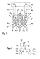
- the tamping aggregate 12 ′ comprises two pairs of tamping tools 14a and 14b mounted one behind the other on a common support 17 ′, these two tamping tools being produced identically, 'as described in relation to Figure 2.
- the two eccentric shafts 18a and 18b are driven by a common motor 44 by means of a belt 43.
- the support 17' is again suspended pendulumally in a vertical longitudinal plane of the machine, as indicated by the arrows in an arc, by means of two hydraulic cylinders 19a and 19b, the lower ends of which are attached at two articulation points 42a and 42b to the support 17 'and whose the upper ends are articulated respectively to two transverse axes 13a and 13b on the chassis 2.
- the parallelogram-shaped structure constituted by the support 17 ', the two hydraulic cylinders 19a and 19b and the part of the chassis 2 at which they are attached ensures a horizontal holding, parallel to the track, of the support 17 ', so that the two pairs of tamping tools 14a and 14b are always at the same height.
- FIG. 6 A variant of this embodiment is shown diagrammatically in FIG. 6.
- two pairs of tamping tools 14a and 14b are provided, each mounted on their own support 17a and 17b at the ends 47a and 47b of a rocker 45 whose midpoint is attached to the end of the piston rod of a hydraulic cylinder 19 'provided for lifting the rocker 45 and whose upper end is suspended pendulumly to the transverse axis 13 on the chassis.
- a parallelogram articulation constituted on the one hand by the jack 19 and the rocker 45 and on the other hand by two arms 48 and 49 articulated together, shown in dotted lines.
- the invention is not limited to the examples of execution described, numerous variants being possible, both with regard to the execution of the tamping aggregate, its oscillating suspension and the control of the tamping cycles.
Landscapes
- Engineering & Computer Science (AREA)
- Architecture (AREA)
- Civil Engineering (AREA)
- Structural Engineering (AREA)
- Machines For Laying And Maintaining Railways (AREA)
- Fertilizers (AREA)
- Glass Compositions (AREA)
- Soil Working Implements (AREA)
- Train Traffic Observation, Control, And Security (AREA)
- Carriers, Traveling Bodies, And Overhead Traveling Cranes (AREA)
- Vehicle Cleaning, Maintenance, Repair, Refitting, And Outriggers (AREA)
- Application Of Or Painting With Fluid Materials (AREA)
Priority Applications (1)
| Application Number | Priority Date | Filing Date | Title |
|---|---|---|---|
| AT82200040T ATE12955T1 (de) | 1981-01-23 | 1982-01-14 | Gleisstopfmaschine. |
Applications Claiming Priority (2)
| Application Number | Priority Date | Filing Date | Title |
|---|---|---|---|
| CH428/81 | 1981-01-23 | ||
| CH428/81A CH652430A5 (de) | 1981-01-23 | 1981-01-23 | Gleisstopfmaschine. |
Publications (2)
| Publication Number | Publication Date |
|---|---|
| EP0057030A1 true EP0057030A1 (de) | 1982-08-04 |
| EP0057030B1 EP0057030B1 (de) | 1985-04-24 |
Family
ID=4186796
Family Applications (1)
| Application Number | Title | Priority Date | Filing Date |
|---|---|---|---|
| EP82200040A Expired EP0057030B1 (de) | 1981-01-23 | 1982-01-14 | Gleisstopfmaschine |
Country Status (10)
| Country | Link |
|---|---|
| US (1) | US4449459A (de) |
| EP (1) | EP0057030B1 (de) |
| JP (1) | JPS57143001A (de) |
| AT (1) | ATE12955T1 (de) |
| AU (1) | AU545691B2 (de) |
| BR (1) | BR8200340A (de) |
| CA (1) | CA1180947A (de) |
| CH (1) | CH652430A5 (de) |
| DE (1) | DE3263190D1 (de) |
| ZA (1) | ZA8255B (de) |
Cited By (3)
| Publication number | Priority date | Publication date | Assignee | Title |
|---|---|---|---|---|
| US4449459A (en) * | 1981-01-23 | 1984-05-22 | Canron Corp. | Pivoting head continuous tamper |
| EP3669803A1 (de) | 2018-12-20 | 2020-06-24 | Oystershell NV | Stift zur herstellung von kohlendioxidtabletten |
| US20220056647A1 (en) * | 2018-10-24 | 2022-02-24 | Plasser & Theurer Export Von Bahnbaumaschinen Gmbh | Track maintenance machine and method for tamping sleepers of a track |
Families Citing this family (13)
| Publication number | Priority date | Publication date | Assignee | Title |
|---|---|---|---|---|
| US4760797A (en) * | 1985-02-20 | 1988-08-02 | Southern Railway Company | Method and apparatus for automated tie detection and tamping |
| US5577446A (en) * | 1995-02-14 | 1996-11-26 | Pandrol Jackson, Inc. | Stoneblower having adjustable workheads and improved blowing tubes |
| US6334396B2 (en) * | 1999-08-02 | 2002-01-01 | Pandrol Jackson, Inc. | Switch stoneblower |
| SE519365C2 (sv) | 2000-07-03 | 2003-02-18 | Bofors Defence Ab | Arrangemang vid uppskjutbar ammunitionsenhet med modulärt uppbyggda stridsdelar |
| US8245646B1 (en) * | 2009-01-26 | 2012-08-21 | Harsco Technologies Corporation | Articulated rail vehicle |
| CN103132407B (zh) * | 2011-11-24 | 2014-10-29 | 金鹰重型工程机械有限公司 | 拖链装置 |
| CN103422404B (zh) * | 2013-08-15 | 2015-05-13 | 中铁四局集团有限公司 | 一种起拨道机上下道装置 |
| HUE042007T2 (hu) | 2014-08-13 | 2019-06-28 | Plasser & Theurer Export Von Bahnbaumaschinen Gmbh | Berendezés vágány stabilizálására |
| AT516873B1 (de) * | 2015-03-03 | 2016-12-15 | Plasser & Theurer Export Von Bahnbaumaschinen Gmbh | Maschine zur Stabilisation eines Gleises |
| WO2017011775A1 (en) | 2015-07-16 | 2017-01-19 | Harsco Technologies LLC | Coil-oscillator vibration unit for rail workhead |
| AT16726U1 (de) * | 2018-09-13 | 2020-07-15 | Plasser & Theurer Export Von Bahnbaumaschinen Gmbh | Verfahren und Vorrichtung zum Unterstopfen von Schwellen eines Gleises |
| AT522237B1 (de) * | 2019-03-14 | 2024-05-15 | Plasser & Theurer Export Von Bahnbaumaschinen Gmbh | Verfahren zum Verdichten eines Schotterbettes eines Gleises |
| AT524861B1 (de) * | 2021-04-12 | 2022-10-15 | Plasser & Theurer Export Von Bahnbaumaschinen Gmbh | Verfahren und Maschine zum Stopfen eines Gleises |
Citations (6)
| Publication number | Priority date | Publication date | Assignee | Title |
|---|---|---|---|---|
| US2899909A (en) * | 1959-08-18 | Ballast tamping machine | ||
| FR1329815A (fr) * | 1961-06-21 | 1963-06-14 | Bourreuse de traverses pour la construction et l'entretien des voies ferrées | |
| DE1928619A1 (de) * | 1968-06-11 | 1970-01-29 | Plasser Bahnbaumasch Franz | Verfahren und Vorrichtung zum Verdichten des Schotterbettes fuer Gleise |
| DE2013991A1 (de) * | 1969-03-24 | 1970-11-12 | ||
| FR2072853A5 (de) * | 1969-12-19 | 1971-09-24 | Plasser Bahnbaumasch Franz | |
| US4068596A (en) * | 1975-08-25 | 1978-01-17 | Franz Plasser Bahnbaumaschinen-Industriegesellschaft M.B.H. | Mobile ballast tamper |
Family Cites Families (13)
| Publication number | Priority date | Publication date | Assignee | Title |
|---|---|---|---|---|
| DE1067837B (de) * | 1956-02-04 | 1959-10-29 | Schwermaschb Heinrich Rau Veb | Steueranlage fuer sich auf dem Gleis gleichmaessig fortbewegende Gleisunterhaltungsmaschinen mit schrittweise vorrueckenden Arbeitsvorrichtungen |
| US3430578A (en) * | 1966-02-18 | 1969-03-04 | Canada Iron Foundries Ltd | Railway track maintenance equipment |
| CH507415A (fr) * | 1969-03-24 | 1971-05-15 | Matisa Materiel Ind Sa | Machine pour le bourrage du ballast des voies ferrées |
| DE1932877A1 (de) * | 1969-06-28 | 1971-01-21 | Windhoff Rheiner Maschf | Auf dem Gleis verfahrbare Vorrichtung zum Verdichten des Schotterbettes |
| AT314581B (de) * | 1969-07-24 | 1974-04-10 | Plasser Bahnbaumasch Franz | Bettungsverdichtmaschine |
| DE2024168A1 (de) * | 1970-05-16 | 1971-12-02 | H Sieke | Auf Eisenbahnschienen verfahrbare Gleisstopfmaschine |
| US3892183A (en) * | 1974-03-18 | 1975-07-01 | Canron Inc | Method and means for consolidating ballast |
| AT350612B (de) * | 1976-12-27 | 1979-06-11 | Plasser Bahnbaumasch Franz | Gleisstopf-nivellier-richtmaschine und ver- fahren zur bearbeitung eines gleises |
| SU633971A1 (ru) * | 1977-06-21 | 1978-11-25 | Всесоюзный Ордена Трудового Красного Знамени Научно-Исследовательский Институт Железнодорожного Транспорта | Машина дл вырезки балласта из шпальных щиков железнодорожного пути |
| US4282815A (en) * | 1979-10-12 | 1981-08-11 | Canron Corp. | Railroad tamping machine |
| CH652430A5 (de) * | 1981-01-23 | 1985-11-15 | Canron Inc Crissier | Gleisstopfmaschine. |
| CH640286A5 (fr) * | 1981-02-24 | 1983-12-30 | Sig Schweiz Industrieges | Bourreuse de voie ferree. |
| CH640902A5 (fr) * | 1981-03-02 | 1984-01-31 | Sig Schweiz Industrieges | Bourreuse de voie ferree. |
-
1981
- 1981-01-23 CH CH428/81A patent/CH652430A5/de not_active IP Right Cessation
-
1982
- 1982-01-06 ZA ZA8255A patent/ZA8255B/xx unknown
- 1982-01-14 EP EP82200040A patent/EP0057030B1/de not_active Expired
- 1982-01-14 AT AT82200040T patent/ATE12955T1/de not_active IP Right Cessation
- 1982-01-14 DE DE8282200040T patent/DE3263190D1/de not_active Expired
- 1982-01-14 AU AU79527/82A patent/AU545691B2/en not_active Ceased
- 1982-01-21 US US06/341,344 patent/US4449459A/en not_active Expired - Fee Related
- 1982-01-22 JP JP57007767A patent/JPS57143001A/ja active Granted
- 1982-01-22 BR BR8200340A patent/BR8200340A/pt unknown
- 1982-01-22 CA CA000394731A patent/CA1180947A/en not_active Expired
Patent Citations (6)
| Publication number | Priority date | Publication date | Assignee | Title |
|---|---|---|---|---|
| US2899909A (en) * | 1959-08-18 | Ballast tamping machine | ||
| FR1329815A (fr) * | 1961-06-21 | 1963-06-14 | Bourreuse de traverses pour la construction et l'entretien des voies ferrées | |
| DE1928619A1 (de) * | 1968-06-11 | 1970-01-29 | Plasser Bahnbaumasch Franz | Verfahren und Vorrichtung zum Verdichten des Schotterbettes fuer Gleise |
| DE2013991A1 (de) * | 1969-03-24 | 1970-11-12 | ||
| FR2072853A5 (de) * | 1969-12-19 | 1971-09-24 | Plasser Bahnbaumasch Franz | |
| US4068596A (en) * | 1975-08-25 | 1978-01-17 | Franz Plasser Bahnbaumaschinen-Industriegesellschaft M.B.H. | Mobile ballast tamper |
Cited By (5)
| Publication number | Priority date | Publication date | Assignee | Title |
|---|---|---|---|---|
| US4449459A (en) * | 1981-01-23 | 1984-05-22 | Canron Corp. | Pivoting head continuous tamper |
| US20220056647A1 (en) * | 2018-10-24 | 2022-02-24 | Plasser & Theurer Export Von Bahnbaumaschinen Gmbh | Track maintenance machine and method for tamping sleepers of a track |
| US12049731B2 (en) * | 2018-10-24 | 2024-07-30 | Plasser & Theurer Export Von Bahnbaumaschinen Gmbh | Track maintenance machine and method for tamping sleepers of a track |
| EP3669803A1 (de) | 2018-12-20 | 2020-06-24 | Oystershell NV | Stift zur herstellung von kohlendioxidtabletten |
| WO2020128027A1 (en) | 2018-12-20 | 2020-06-25 | Oystershell Nv | Cryogenic device and actuator assembly therein |
Also Published As
| Publication number | Publication date |
|---|---|
| JPS57143001A (en) | 1982-09-04 |
| JPH0316441B2 (de) | 1991-03-05 |
| CA1180947A (en) | 1985-01-15 |
| ZA8255B (en) | 1982-11-24 |
| US4449459A (en) | 1984-05-22 |
| ATE12955T1 (de) | 1985-05-15 |
| AU545691B2 (en) | 1985-07-25 |
| CH652430A5 (de) | 1985-11-15 |
| EP0057030B1 (de) | 1985-04-24 |
| AU7952782A (en) | 1982-07-29 |
| DE3263190D1 (en) | 1985-05-30 |
| BR8200340A (pt) | 1982-11-23 |
Similar Documents
| Publication | Publication Date | Title |
|---|---|---|
| EP0057030B1 (de) | Gleisstopfmaschine | |
| BE1007917A3 (fr) | Machine de construction de voie ferree deplacable par roulement de facon continue pour le damage du lit de ballast d'une voie ferree. | |
| FR2470189A1 (fr) | Machine mobile pour nettoyer un lit de ballast, comportant des dispositifs de nivellement et de compactage, et procede pour traiter un lit de ballast a l'aide d'une telle machine | |
| BE1005265A3 (fr) | Procede d'abaissement continu d'une voie ferree dans une position prescrite de niveau ou en hauteur. | |
| FR2657898A1 (fr) | Machine de construction de voie ferree pour le damage du lit de ballast. | |
| FR2532967A1 (fr) | Machine roulante de bourrage de voie ferree a deux chassis de vehicule roulant relies entre eux de facon articulee | |
| FR2465541A1 (fr) | Tour sur fosse pour le profilage des roues sur essieux ferroviaires montes | |
| FR2474554A1 (fr) | Appareil mobile pour le soudage de goujons a des semelles de rail | |
| FR2635126A1 (fr) | Machine mobile de bourrage, levage et dressage de voies ferrees destinee au levage et/ou au decalage lateral d'une voie dans des zones d'aiguillage et de croisement | |
| FR2498218A1 (fr) | Machine pour le bourrage et le nivellement d'une voie ferree, comprenant un dispositif de stabilisation | |
| FR2518603A1 (fr) | Machine de correction de voie mobile avec systeme de reference de mesure | |
| FR2692607A1 (fr) | Machine de construction de voie ferrée comprenant un système de référence à laser et procédé de guidage d'appareils en fonction dudit système. | |
| FR2645885A1 (fr) | Machine de bourrage mobile pour voies ferrees | |
| FR2556752A1 (fr) | Machine de bourrage de voie ferree deplacable par roulement de facon continue | |
| FR2674547A1 (fr) | Machine de construction de voie ferree pour l'abaissement controle d'une voie ferree. | |
| CH632027A5 (fr) | Bourreuse de voies ferrees. | |
| FR2770858A1 (fr) | Machine de construction et de refection de voie ferree avec un systeme de reference a laser et procede pour la mise en oeuvre de celle-ci | |
| FR2565269A1 (fr) | Machine de bourrage, de nivellement et de dressage de voie ferree deplacable par roulement de facon continue | |
| FR2541332A1 (fr) | Machine de nivellement et de bourrage de voie ferree avec ensemble de bourrage et de stabilisation | |
| FR2551782A1 (fr) | Machine de bourrage, de nivellement et de dressage de voie ferree deplacable de facon continue (sans arret) | |
| EP0153213B1 (de) | Kontinuierlich fortschreitende schienenfahrbare Arbeitsmaschine | |
| FR2514525A1 (fr) | Procede de stabilisation d'un mobile suspendu avec au moins une liberte de mouvement par rapport a une trajectoire recherchee et son application a la stabilisation d'une rampe pulverisatrice | |
| FR2550808A1 (fr) | Machine de bourrage, de nivellement et de dressage de voie ferree deplacable de facon continue (sans arret) avec attenuation des chocs pour les operateurs | |
| EP0369879B1 (de) | Vorrichtung zum Auswechseln eines Arbeitsgerätes an Erdbewegungsmaschinen, Erdbewegungsmaschine mit solcher Vorrichtung und ihre Verwendung bei Strassenbauarbeiten | |
| FR2552460A1 (fr) | Machine de bourrage, de nivellement et de dressage de voie ferree deplacable par roulement de facon continue (sans arret) |
Legal Events
| Date | Code | Title | Description |
|---|---|---|---|
| PUAI | Public reference made under article 153(3) epc to a published international application that has entered the european phase |
Free format text: ORIGINAL CODE: 0009012 |
|
| AK | Designated contracting states |
Designated state(s): AT DE FR GB IT |
|
| 17P | Request for examination filed |
Effective date: 19830124 |
|
| RAP1 | Party data changed (applicant data changed or rights of an application transferred) |
Owner name: MATISA MATERIEL INDUSTRIEL S.A. |
|
| ITF | It: translation for a ep patent filed | ||
| GRAA | (expected) grant |
Free format text: ORIGINAL CODE: 0009210 |
|
| AK | Designated contracting states |
Designated state(s): AT DE FR GB IT |
|
| REF | Corresponds to: |
Ref document number: 12955 Country of ref document: AT Date of ref document: 19850515 Kind code of ref document: T |
|
| REF | Corresponds to: |
Ref document number: 3263190 Country of ref document: DE Date of ref document: 19850530 |
|
| PLBE | No opposition filed within time limit |
Free format text: ORIGINAL CODE: 0009261 |
|
| STAA | Information on the status of an ep patent application or granted ep patent |
Free format text: STATUS: NO OPPOSITION FILED WITHIN TIME LIMIT |
|
| 26N | No opposition filed | ||
| ITTA | It: last paid annual fee | ||
| PGFP | Annual fee paid to national office [announced via postgrant information from national office to epo] |
Ref country code: AT Payment date: 19980129 Year of fee payment: 17 |
|
| PG25 | Lapsed in a contracting state [announced via postgrant information from national office to epo] |
Ref country code: AT Free format text: LAPSE BECAUSE OF NON-PAYMENT OF DUE FEES Effective date: 19990114 |
|
| PGFP | Annual fee paid to national office [announced via postgrant information from national office to epo] |
Ref country code: GB Payment date: 20010110 Year of fee payment: 20 |
|
| PGFP | Annual fee paid to national office [announced via postgrant information from national office to epo] |
Ref country code: FR Payment date: 20010123 Year of fee payment: 20 Ref country code: DE Payment date: 20010123 Year of fee payment: 20 |
|
| REG | Reference to a national code |
Ref country code: GB Ref legal event code: IF02 |
|
| PG25 | Lapsed in a contracting state [announced via postgrant information from national office to epo] |
Ref country code: GB Free format text: LAPSE BECAUSE OF EXPIRATION OF PROTECTION Effective date: 20020113 |
|
| REG | Reference to a national code |
Ref country code: GB Ref legal event code: PE20 Effective date: 20020113 |